EP1081648A2 - Method for processing a digital image - Google Patents
Method for processing a digital image Download PDFInfo
- Publication number
- EP1081648A2 EP1081648A2 EP00307387A EP00307387A EP1081648A2 EP 1081648 A2 EP1081648 A2 EP 1081648A2 EP 00307387 A EP00307387 A EP 00307387A EP 00307387 A EP00307387 A EP 00307387A EP 1081648 A2 EP1081648 A2 EP 1081648A2
- Authority
- EP
- European Patent Office
- Prior art keywords
- image
- bins
- images
- processing
- data
- Prior art date
- Legal status (The legal status is an assumption and is not a legal conclusion. Google has not performed a legal analysis and makes no representation as to the accuracy of the status listed.)
- Granted
Links
Images




Classifications
-
- G—PHYSICS
- G06—COMPUTING OR CALCULATING; COUNTING
- G06V—IMAGE OR VIDEO RECOGNITION OR UNDERSTANDING
- G06V10/00—Arrangements for image or video recognition or understanding
- G06V10/20—Image preprocessing
- G06V10/24—Aligning, centring, orientation detection or correction of the image
Definitions
- This invention relates generally to detection of particular images of several documents placed on the platen of an image input device in the presence of severe background bleeding, and more particularly to the automatic detection and segmentation of the series of images placed on the platen using the technologies of joining orphaned images, linear regression algorithms and collinearity detectors.
- a method for processing a digital image using an imaging input device so as to reduce bleeding of the edges of the detected images comprising receiving a digitized image including at least one of a plurality of representations of objects; and processing said digitized image into at least one of a plurality of images of said digitized image wherein said processing step includes defining a plurality of bins having a plurality of edge points making up each of said plurality of images of said digitized image.
- the present invention is directed to a system intended to automatically determine the boundaries of multiple objects within a scanned image of a series of documents.
- the present invention combines a number of graphics and image processing techniques into an automated, system that provides productivity enhancement for digital copiers and scanning systems.
- the present invention accomplishes these objectives by: 1) locating each of the objects within an input image; 2) modeling the shape of the identified object (e.g., rectangle); and 3) positioning the object in a digital image at a predefined locations.
- a method for processing a digital image using an imaging input device reducing bleeding of the edges of the detected images by determining edge contours to generate bounding boxes comprising: identifying bins having edges that approximate 90 degrees, and modeling a rectangular image fitting for bins that approximate the 90 degrees edges.
- a method for processing a digital image comprising the steps of: receiving a digitized image of a plurality of representations of objects; and processing said digitized image into a plurality of images representing said digitized image wherein said processing step includes generating a plurality of bins wherein said bins have a plurality of edge points making up the boundaries of each of said plurality of images of said digitized image.
- a method for processing a digital image using an imaging input device reducing bleeding of the edges of the detected images by determining edge contours to generate bounding boxes comprising: identifying bins on said edge contours having edges that approximate 90 degrees, and modeling a rectangular image for each the identified bins.
- the techniques described herein enable a user to expediently scan a document or other object, automatically recognizing the shape of the document within the digitized image, and composing a digital document incorporating the object.
- the techniques described above are advantageous because they improve the efficiency of a scanning process, in the presence of severe bleeding.
- data refers herein to physical signals that indicate or include information.
- an item of data can indicate one of a number of possible alternatives, the item of data has one of a number of "values.”
- a binary item of data also referred to as a "bit”
- bit has one of two values, interchangeably referred to as "1" and “0” or “ON” and “OFF” or “high” and “low.”
- a bit is an "inverse" of another bit if the two bits have different values.
- An N-bit item of data has one of 2N values.
- a "multi-bit" item of data is an item of data that includes more than one bit.
- Memory circuitry or “memory” is any circuitry that can store data, and may include local and remote memory and input/output devices. Examples include semiconductor ROMs, RAMs, and storage medium access devices with data storage media that they can access.
- a “memory cell” is memory circuitry that can store a single unit of data, such as a bit or other n-array digit or an analog value.
- a signal "indicates” or “selects” one of a set of alternatives if the signal causes the indicated one of the set of alternatives to occur.
- a signal can indicate one bit set in a sequence of bit sets to be used in an operation, in which case the signal causes the indicated bit set to be used in the operation.
- An image may include characters, words, and text as well as other features such as graphics.
- a text may be included in a set of one or more images, such as in images of the pages of a document.
- An image may be processed so as to identify specific within the image, each of which is an image.
- a "bin” is a list of edge points that are approximately collinear. A list of edge points is converted into a sequence of bins that represent the boundaries as straight lines.
- An object may be of any size and shape and has "physical attributes" or characteristics including, but not limited, to position, shape and orientation.
- an object may be a document, when the document is placed on the platen of an image input device and the region of the platen is digitized to produce a representation thereof.
- An item of data "defines" an image when the item of data includes sufficient information to produce the image.
- a two-dimensional array can define all or any part of an image, with each item of data in the array providing a value indicating the color of a respective location of the image.
- An item of data "defines" an image set when the item of data includes sufficient information to produce all the images in the set.
- Each location in an image may be called a "pixel.”
- each value indicating the color of a location may be called a "pixel value”.
- Each pixel value is a bit in a "binary form” of an image, a gray scale value in a “gray scale form” of an image, or a set of color space coordinates in a "color coordinate form” of an image, the binary form, gray scale form, and color coordinate form each being a two-dimensional array defining an image.
- An operation performs "image processing" when it operates on an item of data that relates to part of an image.
- Pixels are "neighbors” or “neighboring” within an image when there are no other pixels between them and they meet an appropriate criterion for neighboring. If the pixels are rectangular and appear in rows and columns within a two-dimensional image, each pixel may have 4 or 8 neighboring pixels, depending on the criterion used.
- edge occurs in an image when two neighboring pixels have sufficiently different pixel values according to an appropriate criterion for the occurrence of an edge between them.
- edge pixel or “boundary pixel” may be applied to one or both of two neighboring pixels between which an edge occurs.
- An “image characteristic” or “characteristic” is a measurable attribute of an image.
- An operation can “measure” a characteristic by producing data indicating the characteristic using data defining an image.
- a characteristic is measured “for an image” if the characteristic is measured in a manner that is likely to produce approximately the same result each time it occurs.
- a "version" of a first image is a second image produced using an item of data defining the first image.
- the second image may be identical to the first image, or it may be modified by loss of resolution, by changing the data defining the first image, or by other processes that results in modifying pixel values of the first image.
- An “image input device” is a device that can receive an image and provide an item of data defining a version of the image.
- a “scanner” is an image input device that receives an image by a scanning operation, such as by scanning a document.
- a scanner may have a transparent surface (platen) or equivalent means to support a document during scanning.
- Other well-known image input devices include digital cameras, facsimile machines, and video recorders, or any image storage device having the capability to store data signals representative of the intensity of light reflected from the surface of objects at which the device is directed.
- a general purpose computer with an image creation program may also be an image input device.
- An “image output device” is a device that can receive an item of data defining an image and provide or render the image as output.
- a “display” is an image output device that provides the output image in human viewable form
- a “printer” is an image output device that renders the output image in a human viewable, hard copy form.
- FIG. 1 depicted therein is a digital printing system 20 in which the present invention finds particular use.
- system 20 may be a Xerox DocuColor® 40 Digital Color Printing System or the Xerox 5775® Digital Color Copier.
- System 20 includes a computer or data processing unit 22 ( Figure 2) capable of receiving digital data representing an image of an original document 24 placed upon a platen of scanner 26.
- Computer 22 initially stores the digital input data from scanner 26 in memory 52 (e.g., RAM or magnetic disk storage) where the image may subsequently be accessed.
- memory 52 may also include program memory for the storage of object code suitable for directing the processor to execute image processing operations in accordance with the invention described herein.
- Computer 22 has associated therewith a user interface (U/I) 28 including one or more user input devices 30, such as a keyboard, a keypad, a mouse, trackball, stylus or equivalent pointing device, etc.
- U/I user interface
- system 20 is a color image output device such as printer 34 which may include a laser-driven, xerographic printing engine as found in a number of commercially available printers.
- system 20 is employed to process the digital image data received as input from a scanner 26, utilizing image processing software running in processor 50, so as to produce an output file that may be rendered by printer 34, stored in memory 50, and/or transmitted to another device via network 40.
- system 20 is depicted as an integrated unit in Figure 1, it will be appreciated that the system may also comprise a plurality of independent yet interconnected units. Referring to Figure 3, it will be appreciated that the document placed upon the scanner platen in system 20 may not be accurately registered along the registration edges 25.
- a particular embodiment to which the following description will be directed is a single document object O placed in a central location on the platen of scanner 26 as illustrated in Figure 3.
- a facsimile transmission system using a set of rollers to advance a document through a scanning nip it will be appreciated that the document may become skewed during the digitization process and that the present application may have particular application to such systems as well.
- the present invention automatically identifies at least the position, shape and orientation angle of the object.
- the process carried out by computer 22 during the processing of the input image includes three general steps. First, at step 100 the object within the image is located and boundaries of the object are generally identified. Once the object is located, the shape of the object is modeled at step 200. Having located the object and modeled its shape, a structured image or similar digital document format representing the image and the object therein can be created as represented by step 300.
- the structured image preferably includes data representing not only the image data itself, but data representing the location, shape or orientation of the object, or some combination thereof.
- the output may be a page description language format or equivalents formats suitable for storing the image information in a retrievable form.
- the scanned input image (or a lower resolution version thereof) is loaded into a memory frame buffer (RAM) where it is analyzed in accordance with the previously described steps.
- RAM memory frame buffer
- the object is distinguishable from the image background (e.g., the platen cover) and that the background of the image is contiguous.
- the object location step 100 is performed by first identifying the background region of the input image 102, characterizing the background region 104, and then using the characteristic of the background region as a seed, identifying all the pixels representing the background region with an adaptive seed fill algorithm 106.
- Background pixels are pixels not associated with any objects, or more simply, they are pixels representative of those regions lying outside of the objects, the values of which are controlled by the "background" against which the objects are placed during scanning (e.g., the underside of the platen cover).
- One embodiment employs the average color of a small region in the upper left-hand corner of the scanned image as an initial estimate of the background color.
- other sampling operations may be employed to determine the background color as described, for example, in US-A-5, 282,091 for a Programmable Apparatus for Determining Document Background Level by Farrell.
- an adaptive algorithm is preferably applied to monitor the background color and to accurately identify the objects.
- An example of a seed fill algorithm suitable for use in the present invention is described in Graphics Gems I , A. Glassner Ed., Academic Press, pp. 275-277, 1990, hereby incorporated by reference.
- An adaptive algorithm is required because the background pixels may have significant color variation resulting from a variation in illumination over the platen area.
- the adaptive seed fill algorithm is applied to the scanned color image data using an initial seed point characterized by the background, for example, the upper-left corner of the image.
- the adaptive seed fill algorithm fills a binary frame buffer with a mask indicating all contiguous pixels identified as background pixels.
- the value of ⁇ is fixed and empirically determined in one embodiment.
- the test conducted at step 112 is: if d ⁇ , then pixel P is a background pixel, else pixel P is a foreground pixel.
- the average background color is adaptively modified at step 114 by taking the average value of the last N pixels that have been classified as background.
- AdAvg' (N*AdAvg-AdAvg+LastVal)/N, where AdAvg' is the modified average, AdAvg is the previous adaptive average, LastVal is the value of the last pixel identified as background, and N is the averaging window.
- AdAvg' (N*AdAvg-AdAvg+LastVal)/N, where AdAvg' is the modified average, AdAvg is the previous adaptive average, LastVal is the value of the last pixel identified as
- the process of obtaining a binary map distinguishing the objects from the background may be accomplished using a simplified thresholding operation based upon the background color.
- the background color may be a function of the color of the platen cover, such as a white cover.
- the digital color production system may employ a spectrally reflective or otherwise distinguishable platen cover that results in a background color that may be detected and distinguished from the objects.
- noisy edges can be optionally smoothed using, for example, morphological filtering.
- contiguous foreground regions are located, step 122, thereby identifying the objects.
- Scanning the background mask generated by the adaptive seed fill operation (step 106) identifies objects. Starting with the upper left hand pixel, the mask is searched in a scan line fashion for a pixel not classified in the mask as a background pixel - thus identifying pixels associated with a foreground object.
- the use of the seed fill algorithm for identifying the background assures that foreground objects are closed, or in other words, a complete boundary is formed about the perimeter of the object.
- tracing its edge identifies the boundary of an object.
- the boundary of the foreground object is traced using a simple 8-connected edge traversal operator which provides an ordered-set of points tracing the edge of the object.
- Such an edge traversal operation employs a contour tracing operation to generate a chain code in a manner similar to word or character based recognition systems.
- R. Bozinovic et al. in "Off-Line Cursive Script Word Recognition", IEEE Transactions describes an 8-connected process, for example, on Pattern Analysis and Machine Intelligence, Vol. 11, No. 1 (January 1989).
- one main object would preferably be selected using any of a number of techniques. For example, object selection could be accomplished by retaining the object with the largest perimeter or based upon the location of the object.
- step 200 is to model the shape of the object.
- the result or output from step 100 is a set of bounding pixels or a set of edge traces preferably organized in the form of a linked list. These pixels or traces can be used to extract the object, but orientation is not yet determined. To improve the quality of the object extraction, the object traces are fitted to a model shape. Orientation information and other characteristics of the object may then be extracted from the fitted parameters.
- step 400 of Figure 7 the 'bin' or result of step 100 i.e. the step of bounding pixels or set of edge traces in the form of a linked list is defined.
- step 410 a reduction of the data set is necessary.
- the linked list defined at step 400 may be too large; in fact, it may be in the order of 1,000 data points or more. Therefore, it is necessary to reduce the amount of data of these 1,000 or so data points.
- Using a factor N divisible into the total data points does such data reduction is performed.
- the factor is around the value of 5, or may be another factor that enables a 100-200 point's border. For example, if there were 1,000 data points, to reduce such a data set to within 100-200 points would require a factor between 5 and 10.
- the data set is then reduced to a set of 100-200 points.
- an estimation of the angle of the line passing through each remaining point on the contour is preformed.
- a modified linear regression in a particular window (W) centered on each point is performed so as to estimate an angle of the line passing through each remaining point of the contour determined by the set of data points.
- W window
- a modified linear regression is done on a small window centered on a point (A) where each linear regression requires a series of additions, multiplication's, and arc tangent calculations.
- the algorithm is modified so as to account for these erratic results.
- a standard regression is used for the lines that are more horizontal in two quadrants with a slope between -45° and +45°.
- the slope angle is determined from the following equations:
- each point associated with an angle is categorized by performing a bin categorizing operation to generate a series of bins. For example, as shown in Figure 9, bins B1, B2, B3, and B4... are generated from a series of angles, which are associated with each point.
- the object of step 430 is to categorize groups of adjacent boundary points that share a common slope, i.e. convert the list of boundary points into a sequence of bins (B1, B2, B3...) where each of the bins consists of a set of collinear points so as to generate a boundary of an image made up of a set of straight line segments.
- boundary point angles of the predecessor points may differ from the angle of the current point by a substantial amount. If, for example, the boundary point' angle differs from the previous point by less than a particular amount E, then the point is added to the current bin. If the boundary point angle differs by more than a particular amount E, then it is assigned to a new bin.
- Each bin (B1, B2, B3%) represents a set of collinear points along the edge.
- the bin categorization is completed and the each point is assigned with the appropriate bin some of the bins contain categorized contain to few data points. Therefore at step 440 of Figure 7 it is necessary to remove the bins which contain few or less than a minimum number of data points. Typically this removal is performed when there are approximately 5 data points. As an example of this removal in Figure 10, the smaller bins A, B, and C are removed because they contain less than 5 data points.
- an average angle of points within each of the remaining bins is determined at step 450.
- the same modified regressions described above are now applied to the remaining bins generating an average slope and average slope angle calculation for each of the remaining bins.
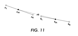
- the remaining bins that share common angles are combined at step 460. These remaining bins were previously not adjacent to each other but became adjacent at step 440 by the removal of small bins found in between the non-adjacent bins. When these bins in between are removed, the bins that are left and that are now adjacent can sometimes be collinear. Therefore, the angle of each bin is checked and if adjacent bins are collinear, the bins are joined into a single bin at step 460.
- Such a procedure is illustrated in Figure 11, were a bin defined by AL-AR and another bin defined by BL-BR are compared to each other. The midpoint between each point AM/BM is calculated and the slope of the segment AB is determined and compared to the slopes of each of the bins. If the slopes are within 10°, an amount designated as E, then the following calculation is performed.
- step 470 the intersection between each bin and the next bin is calculated.
- the midpoint x, y, and slope angle M of each bid is used to calculate the intersection xy between the two bins.
- k 1 y 1 - m 1 x 1
- the edge boundary has been reduced to a small number of bins.
- the next step is to apply a recognition algorithm because the final number of bins usually is 4 for rectangular images.
- the final number of bins usually is 4 for rectangular images.
- This results because smart platens sometimes have regions that are always easily distinguished from the background images and the boundaries of the detected images bleed into the background images. Because of the bleeding, the detected boundaries do not match the actual images in certain locations. Therefore, the boundaries fail to fit the actual image and it is necessary to apply further procedures to make the boundaries fit particular images.
- the list of bins which is generated is browsed to identify bins that have 90° intersections with neighboring bins or the bins that approximate 90° angles with their neighbors. If there are bins that are ascertained to be at 90° angles, then these bins are overlooked because often the bins that have these angles are from images misaligned against the edges of the platen. Therefore, if the bin is found to be a right angle then the bin is more than likely generated from images aligned at platen edge and accordingly should be discarded. Moreover, it is necessary to search for all right or 90° angles because these angles also may correspond to the corners of an image. To be considered a right angle a bin has to lie between 85-95°. As indicated earlier, in step 470 of Figure 7 the angle of intersection is calculated and is used in step 500 to determine whether or not there are right angles.
- step 530 the flow proceeds to determine whether a rectangle can be constructed and can be test fitted to the boundary. To construct a rectangle the following steps shown in the flow chart of Figure 13 are performed.
- step 700 of Figure 13 an estimation of the rotation angle of a rectangle as the slope angle of the right angle of the bin is performed.
- step 710 all the points on the boundary of the rectangle are rotated according to the rotation angle found in step 700.
- step 720 the axis aligned bounding box is calculated. Then the corner coordinates of the axis aligned bounding box are unrotated at step 730. The flow then proceeds to step 540 of Figure 12.
- a test of the similarity measure or similarity fit is performed by counting the number of boundary points in each of the two bins that are at right angles and that lie within a measure of 3 pixels of the resulting bounding box divided by the total number of points in the bin. If the similarity measure is less than .9 the rectangle test is considered to be a good match and the flow proceeds until done. If the similarity test is less than .9 no results are found the flow proceeds to step 500 for the next pair of bins at step 545 and is repeated for the next right angle pair of bins. If no angles have similarity then the flow proceeds to step 550 to an after final search until no bins are left.
- step 560 the longest bin is searched and the flow proceeds to determine if a rectangle can be constructed to be test fitted to the boundary.
- the following steps are necessary as shown in Figure 13. Initially, an estimation of the rotation or angle is determined at step 700, then all the points are rotated at step 710, a calculation of an axis aligned bounding box at step 720 and the corner coordinates of the axis-aligned bounding box are unrotated. The flow then proceeds to step 580. There a rectangular test fit is performed and is determined to be good if the test fit similarity measure is greater than .9 resulting in a good match to be determined.
- Step 560 the flow proceeds back to step 560 and is repeated again for the next longest bin. If the test fit similarity test fails again then the step proceeds to the after final search with no bins left Step 600. The flow then proceeds to Step 610 where the longest bin is searched. Then a rectangle is constructed at step 620 from the longest bin.
- a bounding box has been identified along with its rotation angle.
- the next step is to eliminate those boundaries that are determined not to actual boundaries of the bounding box. If the aspect ratio of the bounding rectangle is more than 15:1 or less than 0.075:1 then a boundary is considered not to be conforming as a boundary of the bounding box and is rejected. Also, if the actual width or height is less than 5 pixels; the boundary is again considered not to be desirable and is rejected.
- a single image may show up as two or more boundaries if the bleeding is excessive.
- a containment algorithm is applied to test if a boundary is contained within another. Each boundary is tested against all other boundaries to see if there is a 25% or more overlap between the two boundaries. If such an overlap occurs, the two boundaries are joined and the bounding rectangle is recalculated (go to step 500).
- the points that make up a boundary are generally the verticals of a many-sided polygon.
- the containment test as shown in Figure 14, is a procedure to calculate the overlap between two polygons P1 and P2.
- a determination of the minimum and maximum P1 & P2 y-values (step 800) for each polygon is performed. In the case of Smart Platen, these values are already known and do not have to be recalculated.
- the minimum and maximum P1 & P2 y-values (step 800) for each polygon is performed.
- these values are already known and do not have to be recalculated.
- X values are determined by scanning through the vertices and determining the min and max values of X for each Y-value (step 820).
- the test for vertical overlap is if the least y-value is greater than the largest y-value step 840, there is no overlap and then the flow proceeds to step 880. Also, if the largest y-value of P, is less than the least Y-value of P2, then there is no overlap, the flow proceeds to step 800. However, for those y-values where both P1 and P2 overlap, the horizontal overlap is summed and the following checks are performed. First, if the minimum x-value of P1 is greater than the maximum x-value of P2 then the flow proceeds to step 860.
Landscapes
- Engineering & Computer Science (AREA)
- Physics & Mathematics (AREA)
- General Physics & Mathematics (AREA)
- Multimedia (AREA)
- Theoretical Computer Science (AREA)
- Image Analysis (AREA)
- Image Input (AREA)
- Facsimile Scanning Arrangements (AREA)
- Facsimile Image Signal Circuits (AREA)
- Studio Devices (AREA)
- Image Processing (AREA)
- Closed-Circuit Television Systems (AREA)
Abstract
Description
if d<ε, then pixel P is a background pixel, else pixel P is a foreground pixel.

Claims (3)
- A method for processing a digital image using an imaging input device so as to reduce bleeding of the edges of the detected images comprising the steps of :receiving a digitized image including at least one of a plurality of representations of objects; andprocessing said digitized image into at least one of a plurality of images of said digitized image wherein said processing step includes defining a plurality of bins having a plurality of edge points making up each of said plurality of images of said digitized image.
- A method for processing a digital image using an imaging input device reducing bleeding of the edges of the detected images by determining edge contours to generate bounding boxes comprising:identifying bins having edges that approximate 90 degrees, andmodeling a rectangular image fitting for bins that approximate the 90 degrees edges.
- A method for processing a digital image using an imaging input device reducing bleeding of the edges of the detected images by determining edge contours to generate bounding boxes comprising:identifying bins on said edge contours having edges that approximate 90 degrees, andmodeling a rectangular image for each the identified bins.
Applications Claiming Priority (2)
| Application Number | Priority Date | Filing Date | Title |
|---|---|---|---|
| US389112 | 1999-09-02 | ||
| US09/389,112 US6704456B1 (en) | 1999-09-02 | 1999-09-02 | Automatic image segmentation in the presence of severe background bleeding |
Publications (3)
| Publication Number | Publication Date |
|---|---|
| EP1081648A2 true EP1081648A2 (en) | 2001-03-07 |
| EP1081648A3 EP1081648A3 (en) | 2002-01-02 |
| EP1081648B1 EP1081648B1 (en) | 2005-05-11 |
Family
ID=23536859
Family Applications (1)
| Application Number | Title | Priority Date | Filing Date |
|---|---|---|---|
| EP00307387A Expired - Lifetime EP1081648B1 (en) | 1999-09-02 | 2000-08-29 | Method for processing a digital image |
Country Status (4)
| Country | Link |
|---|---|
| US (1) | US6704456B1 (en) |
| EP (1) | EP1081648B1 (en) |
| JP (1) | JP4535584B2 (en) |
| DE (1) | DE60020038T2 (en) |
Cited By (3)
| Publication number | Priority date | Publication date | Assignee | Title |
|---|---|---|---|---|
| EP1091320A3 (en) * | 1999-10-04 | 2002-09-11 | Xerox Corporation | Processing multiple digital images |
| RU2596580C2 (en) * | 2014-05-05 | 2016-09-10 | Сяоми Инк. | Method and device for image segmentation |
| US12322092B2 (en) | 2020-02-10 | 2025-06-03 | Tencent Technology (Shenzhen) Company Limited | Medical image processing method and apparatus, image processing method and apparatus, terminal and storage medium |
Families Citing this family (18)
| Publication number | Priority date | Publication date | Assignee | Title |
|---|---|---|---|---|
| JP3922859B2 (en) * | 1999-12-28 | 2007-05-30 | 株式会社リコー | Image processing apparatus, image processing method, and computer-readable recording medium storing program for causing computer to execute the method |
| US6898316B2 (en) * | 2001-11-09 | 2005-05-24 | Arcsoft, Inc. | Multiple image area detection in a digital image |
| JP3845045B2 (en) * | 2002-07-23 | 2006-11-15 | 株式会社リコー | Image processing apparatus, image processing method, image forming apparatus, printing apparatus, and host PC |
| US7606417B2 (en) | 2004-08-16 | 2009-10-20 | Fotonation Vision Limited | Foreground/background segmentation in digital images with differential exposure calculations |
| US7689037B2 (en) | 2004-10-22 | 2010-03-30 | Xerox Corporation | System and method for identifying and labeling fields of text associated with scanned business documents |
| KR100777462B1 (en) * | 2005-01-19 | 2007-11-21 | 삼성전자주식회사 | Scanning apparatus, scanning system having same and scanning method |
| US20060224953A1 (en) * | 2005-04-01 | 2006-10-05 | Xiaofan Lin | Height-width estimation model for a text block |
| US7483179B2 (en) * | 2005-04-28 | 2009-01-27 | Xerox Corporation | Method and system for sending material |
| US20070071324A1 (en) * | 2005-09-27 | 2007-03-29 | Lexmark International, Inc. | Method for determining corners of an object represented by image data |
| JP4085337B2 (en) * | 2006-02-13 | 2008-05-14 | コニカミノルタビジネステクノロジーズ株式会社 | Image forming apparatus |
| IES20060559A2 (en) | 2006-02-14 | 2006-11-01 | Fotonation Vision Ltd | Automatic detection and correction of non-red flash eye defects |
| JP2007221282A (en) * | 2006-02-15 | 2007-08-30 | Konica Minolta Business Technologies Inc | Image processing apparatus |
| US7856142B2 (en) * | 2007-01-26 | 2010-12-21 | Sharp Laboratories Of America, Inc. | Methods and systems for detecting character content in a digital image |
| US8200022B2 (en) * | 2008-03-24 | 2012-06-12 | Verint Systems Ltd. | Method and system for edge detection |
| TWI405145B (en) * | 2008-11-20 | 2013-08-11 | Ind Tech Res Inst | Image segmentation marking method and system based on regional characteristics of pixels, and computer recordable medium |
| KR101189003B1 (en) | 2011-03-30 | 2012-10-08 | 케이오씨엠(주) | Method for converting image file of cartoon contents to image file for mobile |
| US9633444B2 (en) | 2014-05-05 | 2017-04-25 | Xiaomi Inc. | Method and device for image segmentation |
| GB201516953D0 (en) * | 2015-09-25 | 2015-11-11 | Umajin Ltd | Ghost hands |
Family Cites Families (13)
| Publication number | Priority date | Publication date | Assignee | Title |
|---|---|---|---|---|
| DE3580918D1 (en) | 1984-12-14 | 1991-01-24 | Sten Hugo Nils Ahlbom | ARRANGEMENT FOR TREATING IMAGES. |
| US5220398A (en) | 1990-09-28 | 1993-06-15 | Massachusetts Institute Of Technology | Analog VLSI microchip for object position and orientation |
| US5440403A (en) * | 1992-07-24 | 1995-08-08 | Minolta Camera Kabushiki Kaisha | Image reading means for reading a document including a plurality of images and space |
| US5418574A (en) | 1992-10-12 | 1995-05-23 | Matsushita Electric Industrial Co., Ltd. | Video signal correction apparatus which detects leading and trailing edges to define boundaries between colors and corrects for bleeding |
| US5253765A (en) | 1993-01-14 | 1993-10-19 | L.M.B. Electronics, Inc. | Sorting and grading system |
| US5313570A (en) | 1993-03-31 | 1994-05-17 | Miles, Inc. | Method for determining color boundaries for correcting for plate misregistration in color printing |
| US5485568A (en) | 1993-10-08 | 1996-01-16 | Xerox Corporation | Structured image (Sl) format for describing complex color raster images |
| US5528387A (en) | 1994-11-23 | 1996-06-18 | Xerox Corporation | Electronic image registration for a scanner |
| US5974169A (en) | 1997-03-20 | 1999-10-26 | Cognex Corporation | Machine vision methods for determining characteristics of an object using boundary points and bounding regions |
| US6360021B1 (en) * | 1998-07-30 | 2002-03-19 | The Regents Of The University Of California | Apparatus and methods of image and signal processing |
| US6088473A (en) * | 1998-02-23 | 2000-07-11 | Arch Development Corporation | Method and computer readable medium for automated analysis of chest radiograph images using histograms of edge gradients for false positive reduction in lung nodule detection |
| US6240208B1 (en) * | 1998-07-23 | 2001-05-29 | Cognex Corporation | Method for automatic visual identification of a reference site in an image |
| EP0975146B1 (en) * | 1998-07-24 | 2006-08-30 | Xerox Corporation | Locating the position and orientation of multiple objects with a smart platen |
-
1999
- 1999-09-02 US US09/389,112 patent/US6704456B1/en not_active Expired - Fee Related
-
2000
- 2000-08-29 EP EP00307387A patent/EP1081648B1/en not_active Expired - Lifetime
- 2000-08-29 DE DE60020038T patent/DE60020038T2/en not_active Expired - Lifetime
- 2000-09-01 JP JP2000265229A patent/JP4535584B2/en not_active Expired - Fee Related
Cited By (4)
| Publication number | Priority date | Publication date | Assignee | Title |
|---|---|---|---|---|
| EP1091320A3 (en) * | 1999-10-04 | 2002-09-11 | Xerox Corporation | Processing multiple digital images |
| US6839466B2 (en) | 1999-10-04 | 2005-01-04 | Xerox Corporation | Detecting overlapping images in an automatic image segmentation device with the presence of severe bleeding |
| RU2596580C2 (en) * | 2014-05-05 | 2016-09-10 | Сяоми Инк. | Method and device for image segmentation |
| US12322092B2 (en) | 2020-02-10 | 2025-06-03 | Tencent Technology (Shenzhen) Company Limited | Medical image processing method and apparatus, image processing method and apparatus, terminal and storage medium |
Also Published As
| Publication number | Publication date |
|---|---|
| EP1081648B1 (en) | 2005-05-11 |
| US6704456B1 (en) | 2004-03-09 |
| DE60020038T2 (en) | 2005-10-20 |
| JP4535584B2 (en) | 2010-09-01 |
| JP2001101426A (en) | 2001-04-13 |
| EP1081648A3 (en) | 2002-01-02 |
| DE60020038D1 (en) | 2005-06-16 |
Similar Documents
| Publication | Publication Date | Title |
|---|---|---|
| US6839466B2 (en) | Detecting overlapping images in an automatic image segmentation device with the presence of severe bleeding | |
| EP1081648B1 (en) | Method for processing a digital image | |
| US5892854A (en) | Automatic image registration using binary moments | |
| US6738154B1 (en) | Locating the position and orientation of multiple objects with a smart platen | |
| JP3308032B2 (en) | Skew correction method, skew angle detection method, skew correction device, and skew angle detection device | |
| JP3748164B2 (en) | Pattern extraction device | |
| US6898316B2 (en) | Multiple image area detection in a digital image | |
| EP1061469B1 (en) | Method and apparatus for selecting text and/or non-text blocks in a stored document | |
| JP3950777B2 (en) | Image processing method, image processing apparatus, and image processing program | |
| US20070253040A1 (en) | Color scanning to enhance bitonal image | |
| EP1211640A2 (en) | Image processing methods and apparatus for detecting human eyes, human face and other objects in an image | |
| JPH03201866A (en) | Decision of picture skew angle from data including data of compressed form | |
| JP2002133426A (en) | Ruled line extraction device for extracting ruled lines from multi-valued images | |
| CN113392819B (en) | Batch academic image automatic segmentation and labeling device and method | |
| JP3490482B2 (en) | Edge and contour extraction device | |
| US6360006B1 (en) | Color block selection | |
| US8055065B2 (en) | Vectorisation of colour gradients | |
| US20060164517A1 (en) | Method for digital recording, storage and/or transmission of information by means of a camera provided on a comunication terminal | |
| Ablameyko | An introduction to interpretation of graphic images | |
| CN114140620B (en) | A method for detecting straight line contour of an object | |
| JP4221534B2 (en) | Feature extraction method for binary image | |
| EP0975146B1 (en) | Locating the position and orientation of multiple objects with a smart platen | |
| EP0702320A1 (en) | Skew detection | |
| CN117593324A (en) | A method and system for manual marking and correction based on image grayscale calculation method | |
| JP2004094427A (en) | Form image processing apparatus and program for realizing the apparatus |
Legal Events
| Date | Code | Title | Description |
|---|---|---|---|
| PUAI | Public reference made under article 153(3) epc to a published international application that has entered the european phase |
Free format text: ORIGINAL CODE: 0009012 |
|
| AK | Designated contracting states |
Kind code of ref document: A2 Designated state(s): AT BE CH CY DE DK ES FI FR GB GR IE IT LI LU MC NL PT SE Kind code of ref document: A2 Designated state(s): DE FR GB |
|
| AX | Request for extension of the european patent |
Free format text: AL;LT;LV;MK;RO;SI |
|
| PUAL | Search report despatched |
Free format text: ORIGINAL CODE: 0009013 |
|
| AK | Designated contracting states |
Kind code of ref document: A3 Designated state(s): AT BE CH CY DE DK ES FI FR GB GR IE IT LI LU MC NL PT SE |
|
| AX | Request for extension of the european patent |
Free format text: AL;LT;LV;MK;RO;SI |
|
| RIC1 | Information provided on ipc code assigned before grant |
Free format text: 7G 06T 7/00 A, 7G 06T 5/20 B |
|
| 17P | Request for examination filed |
Effective date: 20020702 |
|
| AKX | Designation fees paid |
Free format text: DE FR GB |
|
| 17Q | First examination report despatched |
Effective date: 20021007 |
|
| GRAP | Despatch of communication of intention to grant a patent |
Free format text: ORIGINAL CODE: EPIDOSNIGR1 |
|
| GRAS | Grant fee paid |
Free format text: ORIGINAL CODE: EPIDOSNIGR3 |
|
| GRAA | (expected) grant |
Free format text: ORIGINAL CODE: 0009210 |
|
| AK | Designated contracting states |
Kind code of ref document: B1 Designated state(s): DE FR GB |
|
| REG | Reference to a national code |
Ref country code: GB Ref legal event code: FG4D |
|
| REG | Reference to a national code |
Ref country code: IE Ref legal event code: FG4D |
|
| REF | Corresponds to: |
Ref document number: 60020038 Country of ref document: DE Date of ref document: 20050616 Kind code of ref document: P |
|
| ET | Fr: translation filed | ||
| PLBE | No opposition filed within time limit |
Free format text: ORIGINAL CODE: 0009261 |
|
| STAA | Information on the status of an ep patent application or granted ep patent |
Free format text: STATUS: NO OPPOSITION FILED WITHIN TIME LIMIT |
|
| 26N | No opposition filed |
Effective date: 20060214 |
|
| PGFP | Annual fee paid to national office [announced via postgrant information from national office to epo] |
Ref country code: DE Payment date: 20130722 Year of fee payment: 14 |
|
| PGFP | Annual fee paid to national office [announced via postgrant information from national office to epo] |
Ref country code: FR Payment date: 20130820 Year of fee payment: 14 Ref country code: GB Payment date: 20130725 Year of fee payment: 14 |
|
| REG | Reference to a national code |
Ref country code: DE Ref legal event code: R119 Ref document number: 60020038 Country of ref document: DE |
|
| GBPC | Gb: european patent ceased through non-payment of renewal fee |
Effective date: 20140829 |
|
| REG | Reference to a national code |
Ref country code: FR Ref legal event code: ST Effective date: 20150430 |
|
| PG25 | Lapsed in a contracting state [announced via postgrant information from national office to epo] |
Ref country code: GB Free format text: LAPSE BECAUSE OF NON-PAYMENT OF DUE FEES Effective date: 20140829 Ref country code: DE Free format text: LAPSE BECAUSE OF NON-PAYMENT OF DUE FEES Effective date: 20150303 |
|
| PG25 | Lapsed in a contracting state [announced via postgrant information from national office to epo] |
Ref country code: FR Free format text: LAPSE BECAUSE OF NON-PAYMENT OF DUE FEES Effective date: 20140901 |