EP1081631A2 - A method and apparatus for illumination control to increase the manufacturing yield for a bar code and position reference reader in a mass storage auto-changer - Google Patents
A method and apparatus for illumination control to increase the manufacturing yield for a bar code and position reference reader in a mass storage auto-changer Download PDFInfo
- Publication number
- EP1081631A2 EP1081631A2 EP00306527A EP00306527A EP1081631A2 EP 1081631 A2 EP1081631 A2 EP 1081631A2 EP 00306527 A EP00306527 A EP 00306527A EP 00306527 A EP00306527 A EP 00306527A EP 1081631 A2 EP1081631 A2 EP 1081631A2
- Authority
- EP
- European Patent Office
- Prior art keywords
- optical system
- target
- intensity
- light
- detected
- Prior art date
- Legal status (The legal status is an assumption and is not a legal conclusion. Google has not performed a legal analysis and makes no representation as to the accuracy of the status listed.)
- Withdrawn
Links
Images



Classifications
-
- G—PHYSICS
- G06—COMPUTING OR CALCULATING; COUNTING
- G06K—GRAPHICAL DATA READING; PRESENTATION OF DATA; RECORD CARRIERS; HANDLING RECORD CARRIERS
- G06K7/00—Methods or arrangements for sensing record carriers, e.g. for reading patterns
- G06K7/10—Methods or arrangements for sensing record carriers, e.g. for reading patterns by electromagnetic radiation, e.g. optical sensing; by corpuscular radiation
- G06K7/10544—Methods or arrangements for sensing record carriers, e.g. for reading patterns by electromagnetic radiation, e.g. optical sensing; by corpuscular radiation by scanning of the records by radiation in the optical part of the electromagnetic spectrum
- G06K7/10554—Moving beam scanning
- G06K7/10564—Light sources
- G06K7/10584—Source control
Definitions
- the present invention relates generally to illumination control and more specifically to increasing the manufacturing yield in an optical system used for reading bar codes and position reference marks, by adjusting the intensity of the illumination source with pulse width modulation (PWM).
- PWM pulse width modulation
- Jukebox storage devices typically contain a number of data cartridges. These data cartridges are typically stored in cartridge magazines.
- the magazines typically contain a number of slots or spaces where the data cartridges can be stored.
- the jukebox may contain a plurality of magazines. Typically the magazines are removable from the jukebox storage device for easier access to the magazines so the magazines can be loaded with data cartridges.
- each data cartridge is labeled such that the jukebox storage device can identify and keep track of the location of each data cartridge.
- the data cartridge is labeled with a barcode and the jukebox storage device contains an optical system that can read bar codes.
- the optical system is typically referred to as a barcode reader, however the optical system typically is used for tasks in addition to reading barcodes.
- the jukebox storage device also needs to be able to determine if a magazine is loaded into the jukebox and if a slot or space in the magazine contains a data cartridge.
- the magazines are labeled such that the jukebox storage device can use the barcode reader to detect if a magazine is present.
- the barcode reader can also be used to determine the location of the magazine.
- the jukebox storage device also typically uses the barcode reader to determine if a slot or space in the magazine contains a data cartridge. Because the barcode reader in the jukebox storage device is used for a number of different tasks (i.e. cartridge detection, magazine detection, magazine location, and cartridge identification) the intensity of light detected by the barcode reader from a given target needs to be well defined.
- the barcode reader (see figure 1) contained within a jukebox storage device uses a charged coupled device (CCD) (102) to measure the reflected light, a light emitting diode (LED) (110) as the illumination source and two lenses, one lens (108) to focus the light from the LED (110) onto the target (106) and one lens (104) to focus the reflected light from the target (106) onto the CCD (102).
- CCD charged coupled device
- LED light emitting diode
- Each of the elements of the barcode reader typically has some manufacturing tolerance that creates differences in the performance of the total barcode reader. For example two LED's created by the same manufacturing process typically have a different light output for the same electrical input.
- Alignment of the LED to its focusing lens and the alignment of the CCD to its focusing lens can also affect the amount of light detected by the CCD for a given target. Because of the differences in the individual part tolerances and the alignment tolerances of the optical system the total variation of light detected at the CCD for a given target between two different barcode readers can be as large as 50%. This large variation in light detected between two different barcode readers makes it difficult for barcode readers to be able to fulfill all of the required tasks.
- Figure 2 shows a typical target used to determine the presence of a magazine in a jukebox storage device.
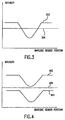
- Figure 3 shows the intensity of the detected light (302) from the target as the barcode reader sweeps across the target.
- Figure 4 shows the intensity of the detected light from a target when the light that makes it through the system is too low (404) and when the light that makes it through the system is too high (402).
- the intensity never falls below the threshold (406) and no target is detected.
- the intensity never gets above the threshold (406) and no target is detected.
- One way to overcome this variation in barcode readers is to measure the light detected by the barcode readers with a given target and keep the barcode readers that meet a narrow tolerance of detected light. Because the required tolerance on the measured reflected light is small and the variation in the measured reflected light is large, the yield of usable barcode readers is small.
- a method and apparatus that allows the adjustment of the intensity of the illumination source in a barcode reader, using the barcode reader as the measuring device, to give a predetermined amount of light from a known target.
- the adjustment of the intensity of the illumination source in the barcode reader compensates for the manufacturing tolerances of the barcode reader.
- the manufacturing yield of the optical system can be increased.
- This method will compensate for the manufacturing tolerances of the individual parts and the degradation due to misalignment of the optical system.
- Some of the manufacturing tolerances that are compensated are: 1) the variation in intensity between different LED's 2) the variation in the transmission of light between different LED focus lenses 3) the variation in focal length between different LED focus lenses 4) the variation in transmission of light between different CCD focus lenses 5) the variation in focal lengths between different CCD focus lenses 6) and the variation in responsiveness between different CCD's.
- Some of the degradation in intensity due to alignment variations that are compensated are: 1) the alignment between the LED and the LED focus lens 2) the alignment of the LED to the CCD 3) and the alignment between the CCD focusing lens and the CCD.
- the optical system comprises an illumination source, typically an LED, a light detection device, typically a CCD, and two lenses.
- the first lens is used to focus the light from the LED to the viewing area of the CCD.
- the second lens is used to focus the light from the viewing area onto the CCD.
- the optical system is built as a subassembly that can be attached to the jukebox storage device after calibration.
- the optical system subassembly has reference mounting surfaces used to align the optical system subassembly with respect to the jukebox storage device.
- the optical system subassembly calibration fixture uses the reference mounting surfaces to mount and align the optical system subassembly in the calibration fixture.
- the calibration fixture has a target (502) that is positioned at a distance (504) from the mounting surfaces (506) that corresponds to the nominal distance that the magazine location targets and the cartridge ID targets will be located at in the jukebox storage device.
- Figure 5 shows a simple embodiment of the mounting surfaces for clarity, as one skilled in the art would realize there are many different configurations for mounting surfaces.
- the calibration fixture also contains the electronics required to read the intensity of the light hitting the CCD (508) and the electronics required to drive the LED (510), in the optical system subassembly (512), at different intensity levels.
- the LED intensity can be controlled by pulse width modulation of the driving voltage.
- the voltage drives a voltage to current converter that produces a constant current that is proportional to the pulse duty cycle of the input voltage.
- Pulse width modulation changes the intensity of the LED by changing the percent of time that the voltage driving the current converter is at a high value. For example, for high light intensity the pulse width (602) of the high voltage driving the current converter is at 90% (see figure 6). For a medium light intensity, the pulse width (702), or percent of high voltage time, can be set to 50% (see figure 7). For a low light intensity, the pulse width of the driving voltage can be set to 10% (not shown). In one embodiment of the present invention there are 128 different levels that the pulse width can be set at corresponding to 128 different intensity level for the LED. As one skilled in the art would know, the number of levels of pulse width modulation can be increased or decreased depending on the minimum change in light required.
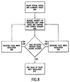
- the optical system subassembly is mounted into the calibration fixture, using the mounting surfaces, and the LED is turned on at a set pulse width (802).
- the intensity of the light detected by the CCD is measured and compared with the desired intensity (804). If the intensity of light is higher than the desired intensity the pulse width modulation is reduced (806). If the intensity of light is lower than the desired intensity the pulse width modulation is increased (808). If the intensity of light matches the desired intensity, within some tolerance range, the value of the pulse width modulation is stored (810) for later use by the jukebox storage device.
- the correct pulse width modulation for that optical subassembly is communicated to the jukebox storage device such that when the jukebox storage device uses the optical system subassembly the jukebox storage device drives the LED using the stored pulse width modulation value that was determined by the calibration fixture.
- the calibration fixture could set the intensity of the LED to each of the 128 values and then measure the intensity of light detected by the optical system.
- the selection of the correct LED driving value for the desired detected intensity could be done as a separate step.
- the embodiment was chosen and described in order to best explain the principles of the invention and its practical application to thereby enable others skilled in the art to best utilize the invention in various embodiments and various modifications as are suited to the particular use contemplated. It is intended that the appended claims be construed to include other alternative embodiments of the invention except insofar as limited by the prior art.
Landscapes
- Physics & Mathematics (AREA)
- Engineering & Computer Science (AREA)
- Electromagnetism (AREA)
- Artificial Intelligence (AREA)
- Toxicology (AREA)
- General Health & Medical Sciences (AREA)
- Health & Medical Sciences (AREA)
- Computer Vision & Pattern Recognition (AREA)
- General Physics & Mathematics (AREA)
- Theoretical Computer Science (AREA)
- Circuit Arrangement For Electric Light Sources In General (AREA)
- Exposure And Positioning Against Photoresist Photosensitive Materials (AREA)
- Automatic Tape Cassette Changers (AREA)
Abstract
Description
Claims (6)
- A method of compensating for the manufacturing tolerances in an optical system used in a mass storage auto-changer, comprising:placing a target, the target having a reflectance, at a known position with respect to the optical system (802);illuminating the target (802) with the illumination source of the optical system;measuring the amount of light (804) detected by the optical system that was reflected from the target;adjusting the output of the illumination source (808, 806), using the measured detected light, to give a known amount of detected light.
- The method of claim 1 further comprising:Storing, for later use, the value of output illumination (810) that gives the known amount of detected light for the optical system.
- The method of claim 2 where the illumination source is an LED and the output of the LED is adjusted by pulse width modulation of the voltage driving the LED.
- A device used to compensating for the manufacturing tolerances in an optical system, used in a jukebox storage device, comprising:a reference mounting system (506) that mounts the optical system;a target (502), the target positioned a know distance (504) from the reference mounting system, the target having a reflectance;a power system (510) that attaches to the optical system and drives the illumination source of the optical system at varying intensities;a measuring circuit (508), that attaches to the optical system, configured to measure the intensity of light detected by the optical system.
- The device of claim 4, further comprising:a desired value for the intensity of light detected by the optical system;a comparator that compares the value of the measured intensity to the desired value of the intensity.
- A method of compensating for the manufacturing tolerances in an optical system used in a mass storage auto-changer, comprising:1) placing a target, the target having a reflectance, at a known position with respect to the optical system;2) illuminating the target with the illumination source of the optical system;3) measuring the amount of light detected by the optical system that was reflected from the target;4) changing the illuminating intensity;5) repeating steps 3 and 4 until the detected light has been measured at each possible illumination intensity.
Applications Claiming Priority (2)
| Application Number | Priority Date | Filing Date | Title |
|---|---|---|---|
| US09/373,471 US6557764B1 (en) | 1999-08-12 | 1999-08-12 | Method and apparatus for illumination control to increase the manufacturing yield for a bar code and position reference reader in a mass storage auto-changer |
| US373471 | 1999-08-12 |
Publications (2)
| Publication Number | Publication Date |
|---|---|
| EP1081631A2 true EP1081631A2 (en) | 2001-03-07 |
| EP1081631A3 EP1081631A3 (en) | 2003-02-05 |
Family
ID=23472561
Family Applications (1)
| Application Number | Title | Priority Date | Filing Date |
|---|---|---|---|
| EP00306527A Withdrawn EP1081631A3 (en) | 1999-08-12 | 2000-07-31 | A method and apparatus for illumination control to increase the manufacturing yield for a bar code and position reference reader in a mass storage auto-changer |
Country Status (3)
| Country | Link |
|---|---|
| US (1) | US6557764B1 (en) |
| EP (1) | EP1081631A3 (en) |
| JP (1) | JP2001084327A (en) |
Cited By (2)
| Publication number | Priority date | Publication date | Assignee | Title |
|---|---|---|---|---|
| US10113911B2 (en) | 2016-06-30 | 2018-10-30 | Gooee Limited | Automated dynamic luminaire identification using barcodes |
| WO2018198070A1 (en) * | 2017-04-26 | 2018-11-01 | Gooee Limited | Automated dynamic luminaire identification using barcodes |
Families Citing this family (7)
| Publication number | Priority date | Publication date | Assignee | Title |
|---|---|---|---|---|
| US20030048375A1 (en) * | 2001-09-11 | 2003-03-13 | Thorstein Seim | Method and apparatus for digitizing light measurements by computer control of light source emission |
| JP5226354B2 (en) * | 2008-03-27 | 2013-07-03 | オリンパス株式会社 | Wireless imaging system and imaging apparatus |
| US20120031975A1 (en) * | 2010-08-04 | 2012-02-09 | The Code Corporation | Illumination blocks for a graphical code reader |
| US8632011B2 (en) | 2011-01-18 | 2014-01-21 | Datalogic ADC, Inc. | Systems and methods for illuminating a scan volume of an optical code reader |
| US9297900B2 (en) | 2013-07-25 | 2016-03-29 | Hand Held Products, Inc. | Code symbol reading system having adjustable object detection |
| JP2016076283A (en) * | 2014-10-06 | 2016-05-12 | 富士通株式会社 | Data determination device, library device, and data determination method |
| CN204256748U (en) * | 2014-10-31 | 2015-04-08 | 霍尼韦尔国际公司 | There is the scanner of illuminator |
Family Cites Families (23)
| Publication number | Priority date | Publication date | Assignee | Title |
|---|---|---|---|---|
| US4097732A (en) * | 1977-06-02 | 1978-06-27 | Burroughs Corporation | Automatic gain control for photosensing devices |
| US4677287A (en) * | 1982-07-14 | 1987-06-30 | Canon Kabushiki Kaisha | Document reader with light source control |
| JPH01167139A (en) * | 1987-12-23 | 1989-06-30 | Brother Ind Ltd | Optical sensor control device |
| US4933538A (en) * | 1988-10-21 | 1990-06-12 | Symbol Technologies, Inc. | Scanning system with adjustable light output and/or scanning angle |
| US5446272A (en) * | 1989-06-16 | 1995-08-29 | Symbol Technologies, Inc. | System for digitizing a scanned signal indicating changes in signal intensity |
| US5303214A (en) * | 1992-01-03 | 1994-04-12 | International Business Machines Corporation | Multi-media-type automatic libraries |
| US5349172A (en) * | 1992-02-27 | 1994-09-20 | Alex Roustaei | Optical scanning head |
| US5550362A (en) | 1992-11-20 | 1996-08-27 | Intermec Corporation | Method and apparatus for calibrating a bar code scanner |
| US5514864A (en) * | 1994-03-25 | 1996-05-07 | Umax Data System Inc. | Photo electric feedback compensation controlled apparatus |
| JP3213670B2 (en) * | 1994-05-30 | 2001-10-02 | 東芝テック株式会社 | Checkout device |
| US5815200A (en) * | 1994-07-26 | 1998-09-29 | Metanetics Corporation | Extended working range dataform reader with reduced power consumption |
| US5542078A (en) * | 1994-09-29 | 1996-07-30 | Ontos, Inc. | Object oriented data store integration environment for integration of object oriented databases and non-object oriented data facilities |
| US5581071A (en) * | 1994-12-06 | 1996-12-03 | International Business Machines Corporation | Barcode scanner with adjustable light source intensity |
| JP2904041B2 (en) * | 1995-01-18 | 1999-06-14 | ヤマハ株式会社 | Disc playback device and remote control device therefor |
| EP0735361B1 (en) * | 1995-03-31 | 2006-05-31 | LINTEC Corporation | Apparatus for inspecting semiconductor substrates |
| JP3629581B2 (en) * | 1995-04-13 | 2005-03-16 | 株式会社キーエンス | Bar code reader |
| US5636040A (en) * | 1995-08-01 | 1997-06-03 | Acer Peripherals, Inc. | Automatic intensity control of the lamp within image scanning apparatus |
| US5729464A (en) * | 1995-09-29 | 1998-03-17 | International Business Machines Corporation | Media identification in an automated data library |
| DE29804040U1 (en) * | 1998-03-07 | 1998-05-14 | Lehner Optoelectronic GmbH, 79312 Emmendingen | Contrast reader |
| US6095417A (en) * | 1998-04-07 | 2000-08-01 | Eastman Kodak Company | Apparatus and method for reading bar codes on a moving web |
| US6262863B1 (en) * | 1998-07-01 | 2001-07-17 | Storage Technology Corporation | Automated storage library with rail mechanism providing flexible robot access |
| US6194697B1 (en) * | 1999-04-13 | 2001-02-27 | Hewlett-Packard Company | Calibration system for an imaging apparatus and method |
| US6246642B1 (en) * | 1999-04-13 | 2001-06-12 | Hewlett-Packard Company | Automated optical detection system and method |
-
1999
- 1999-08-12 US US09/373,471 patent/US6557764B1/en not_active Expired - Fee Related
-
2000
- 2000-07-31 EP EP00306527A patent/EP1081631A3/en not_active Withdrawn
- 2000-08-11 JP JP2000243977A patent/JP2001084327A/en not_active Withdrawn
Cited By (2)
| Publication number | Priority date | Publication date | Assignee | Title |
|---|---|---|---|---|
| US10113911B2 (en) | 2016-06-30 | 2018-10-30 | Gooee Limited | Automated dynamic luminaire identification using barcodes |
| WO2018198070A1 (en) * | 2017-04-26 | 2018-11-01 | Gooee Limited | Automated dynamic luminaire identification using barcodes |
Also Published As
| Publication number | Publication date |
|---|---|
| US6557764B1 (en) | 2003-05-06 |
| JP2001084327A (en) | 2001-03-30 |
| EP1081631A3 (en) | 2003-02-05 |
Similar Documents
| Publication | Publication Date | Title |
|---|---|---|
| US6557764B1 (en) | Method and apparatus for illumination control to increase the manufacturing yield for a bar code and position reference reader in a mass storage auto-changer | |
| EP0803866B1 (en) | Optical storage apparatus | |
| US7009923B2 (en) | Method of and apparatus for recording information | |
| US8344652B2 (en) | Optical measuring apparatus | |
| JP2004296841A (en) | Projection display device, illumination device, and method for measuring element characteristics of semiconductor light source for display device | |
| US6944109B2 (en) | Automatic control method for generating stable laser power of an optical disk drive | |
| KR20170022891A (en) | Image forming apparatus | |
| US6026246A (en) | Distance measuring apparatus | |
| US4963916A (en) | Photographic camera | |
| EP0621970A1 (en) | Portable optical reader system | |
| US20090273930A1 (en) | Light-Emitting Diode Module, Method for Producing a Light-Emitting Diode Module and Optical Projection Apparatus | |
| US7586822B2 (en) | Optical drive controller providing calibrated laser diode driver | |
| US7680166B2 (en) | Laser drive, optical disc apparatus, and laser-driving method | |
| US20030099174A1 (en) | Optical disk device and luminescent power control method for semiconductor laser | |
| EP0364213A1 (en) | Method and apparatus for driving light source by stored current value and for processing information | |
| JPH1183743A (en) | Fluorometer and method for detecting fluorescent signal | |
| US7272103B2 (en) | Laser power monitor device, optical pickup including the same, and optical recording and/or reproducing apparatus including the same | |
| EP1376559A2 (en) | Pickup device and information recording apparatus | |
| US8593495B2 (en) | Image forming apparatus that forms image by scanning photosensitive member with multiple beams | |
| US7842910B2 (en) | Control of light emitting and receiving elements of optical module based on property data associated with elements as stored on memory circuit of optical module | |
| EP4614966A1 (en) | In-chamber device and method for calibrating a tunable focus camera system | |
| US6487371B1 (en) | Range finder device having mode for removing steady light components and mode for not removing steady light components | |
| JP2001007994A (en) | Low power lighting equipment | |
| EP1128377A1 (en) | A method and apparatus for measuring the cartridge magazine insertion distance with a barcode reader | |
| EP1288842B1 (en) | Adjustable focus imaging device |
Legal Events
| Date | Code | Title | Description |
|---|---|---|---|
| PUAI | Public reference made under article 153(3) epc to a published international application that has entered the european phase |
Free format text: ORIGINAL CODE: 0009012 |
|
| AK | Designated contracting states |
Kind code of ref document: A2 Designated state(s): AT BE CH CY DE DK ES FI FR GB GR IE IT LI LU MC NL PT SE |
|
| AX | Request for extension of the european patent |
Free format text: AL;LT;LV;MK;RO;SI |
|
| RAP1 | Party data changed (applicant data changed or rights of an application transferred) |
Owner name: HEWLETT-PACKARD COMPANY, A DELAWARE CORPORATION |
|
| PUAL | Search report despatched |
Free format text: ORIGINAL CODE: 0009013 |
|
| AK | Designated contracting states |
Designated state(s): AT BE CH CY DE DK ES FI FR GB GR IE IT LI LU MC NL PT SE |
|
| AX | Request for extension of the european patent |
Extension state: AL LT LV MK RO SI |
|
| RIC1 | Information provided on ipc code assigned before grant |
Ipc: 7H 04N 1/00 B Ipc: 7G 06K 7/10 A |
|
| 17P | Request for examination filed |
Effective date: 20030409 |
|
| AKX | Designation fees paid |
Designated state(s): DE FR GB |
|
| 17Q | First examination report despatched |
Effective date: 20050624 |
|
| STAA | Information on the status of an ep patent application or granted ep patent |
Free format text: STATUS: THE APPLICATION IS DEEMED TO BE WITHDRAWN |
|
| 18D | Application deemed to be withdrawn |
Effective date: 20051105 |
|
| RIN1 | Information on inventor provided before grant (corrected) |
Inventor name: IRWIN, RICHARD A. Inventor name: GARDNER, RICHARD L., JR. Inventor name: REASONER, KELLY J. |