EP1081580A1 - Portable information processing apparatus - Google Patents
Portable information processing apparatus Download PDFInfo
- Publication number
- EP1081580A1 EP1081580A1 EP00118255A EP00118255A EP1081580A1 EP 1081580 A1 EP1081580 A1 EP 1081580A1 EP 00118255 A EP00118255 A EP 00118255A EP 00118255 A EP00118255 A EP 00118255A EP 1081580 A1 EP1081580 A1 EP 1081580A1
- Authority
- EP
- European Patent Office
- Prior art keywords
- extension device
- information processing
- portable information
- cabinet
- processing apparatus
- Prior art date
- Legal status (The legal status is an assumption and is not a legal conclusion. Google has not performed a legal analysis and makes no representation as to the accuracy of the status listed.)
- Granted
Links
Images


Classifications
-
- G—PHYSICS
- G06—COMPUTING OR CALCULATING; COUNTING
- G06F—ELECTRIC DIGITAL DATA PROCESSING
- G06F1/00—Details not covered by groups G06F3/00 - G06F13/00 and G06F21/00
- G06F1/16—Constructional details or arrangements
- G06F1/1613—Constructional details or arrangements for portable computers
- G06F1/1615—Constructional details or arrangements for portable computers with several enclosures having relative motions, each enclosure supporting at least one I/O or computing function
- G06F1/1616—Constructional details or arrangements for portable computers with several enclosures having relative motions, each enclosure supporting at least one I/O or computing function with folding flat displays, e.g. laptop computers or notebooks having a clamshell configuration, with body parts pivoting to an open position around an axis parallel to the plane they define in closed position
-
- G—PHYSICS
- G06—COMPUTING OR CALCULATING; COUNTING
- G06F—ELECTRIC DIGITAL DATA PROCESSING
- G06F1/00—Details not covered by groups G06F3/00 - G06F13/00 and G06F21/00
- G06F1/16—Constructional details or arrangements
- G06F1/1613—Constructional details or arrangements for portable computers
- G06F1/1633—Constructional details or arrangements of portable computers not specific to the type of enclosures covered by groups G06F1/1615 - G06F1/1626
- G06F1/1635—Details related to the integration of battery packs and other power supplies such as fuel cells or integrated AC adapter
-
- G—PHYSICS
- G06—COMPUTING OR CALCULATING; COUNTING
- G06F—ELECTRIC DIGITAL DATA PROCESSING
- G06F1/00—Details not covered by groups G06F3/00 - G06F13/00 and G06F21/00
- G06F1/16—Constructional details or arrangements
- G06F1/1613—Constructional details or arrangements for portable computers
- G06F1/1633—Constructional details or arrangements of portable computers not specific to the type of enclosures covered by groups G06F1/1615 - G06F1/1626
- G06F1/1656—Details related to functional adaptations of the enclosure, e.g. to provide protection against EMI, shock, water, or to host detachable peripherals like a mouse or removable expansions units like PCMCIA cards, or to provide access to internal components for maintenance or to removable storage supports like CDs or DVDs, or to mechanically mount accessories
-
- G—PHYSICS
- G06—COMPUTING OR CALCULATING; COUNTING
- G06F—ELECTRIC DIGITAL DATA PROCESSING
- G06F1/00—Details not covered by groups G06F3/00 - G06F13/00 and G06F21/00
- G06F1/16—Constructional details or arrangements
- G06F1/1613—Constructional details or arrangements for portable computers
- G06F1/1633—Constructional details or arrangements of portable computers not specific to the type of enclosures covered by groups G06F1/1615 - G06F1/1626
- G06F1/1656—Details related to functional adaptations of the enclosure, e.g. to provide protection against EMI, shock, water, or to host detachable peripherals like a mouse or removable expansions units like PCMCIA cards, or to provide access to internal components for maintenance or to removable storage supports like CDs or DVDs, or to mechanically mount accessories
- G06F1/166—Details related to functional adaptations of the enclosure, e.g. to provide protection against EMI, shock, water, or to host detachable peripherals like a mouse or removable expansions units like PCMCIA cards, or to provide access to internal components for maintenance or to removable storage supports like CDs or DVDs, or to mechanically mount accessories related to integrated arrangements for adjusting the position of the main body with respect to the supporting surface, e.g. legs for adjusting the tilt angle
-
- Y—GENERAL TAGGING OF NEW TECHNOLOGICAL DEVELOPMENTS; GENERAL TAGGING OF CROSS-SECTIONAL TECHNOLOGIES SPANNING OVER SEVERAL SECTIONS OF THE IPC; TECHNICAL SUBJECTS COVERED BY FORMER USPC CROSS-REFERENCE ART COLLECTIONS [XRACs] AND DIGESTS
- Y10—TECHNICAL SUBJECTS COVERED BY FORMER USPC
- Y10T—TECHNICAL SUBJECTS COVERED BY FORMER US CLASSIFICATION
- Y10T292/00—Closure fasteners
- Y10T292/08—Bolts
- Y10T292/096—Sliding
- Y10T292/1014—Operating means
- Y10T292/1022—Rigid
- Y10T292/1025—Padlock or seal catch
-
- Y—GENERAL TAGGING OF NEW TECHNOLOGICAL DEVELOPMENTS; GENERAL TAGGING OF CROSS-SECTIONAL TECHNOLOGIES SPANNING OVER SEVERAL SECTIONS OF THE IPC; TECHNICAL SUBJECTS COVERED BY FORMER USPC CROSS-REFERENCE ART COLLECTIONS [XRACs] AND DIGESTS
- Y10—TECHNICAL SUBJECTS COVERED BY FORMER USPC
- Y10T—TECHNICAL SUBJECTS COVERED BY FORMER US CLASSIFICATION
- Y10T70/00—Locks
- Y10T70/50—Special application
Definitions
- the present invention relates to portable information processing apparatuses and, more specifically, to a portable information processing apparatus capable of accommodating an extension apparatus, typically a disk drive, as a storage apparatus and battery.
- portable information processing apparatuses typically notebook PCs, often accommodate disk drives such as CD (Compact Disk), DVD, and FD (Floppy Disk) drives.
- disk drives such as CD (Compact Disk), DVD, and FD (Floppy Disk) drives.
- some PCs may accommodate a second battery pack to extend its drive time when carried.
- not all of these extension devices can be accommodated at once in a thin, lightweight portable information processing apparatus. Therefore, one of these devices is selected for use as required, and is installed in a bay of the portable information processing apparatus.
- the conventional portable inforamtio apparatus PIP apparatus PIc includes a cabinet 41, and a display unit 42 movably mounted on the cabinet 41 with a hinge 43.
- a U-shaped bay 41a is provided on one side of the cabinet 41 for installing an extension device 45 such as a disk drive in a detouchable manner.
- the extension device 45 has a connector (not shown) for removably engaging another connector (not shown) provided inside the bay 41a of the cabinet 41.
- the bay 41a is formed so that its height L5 is larger than a thickness L6 of the extension device (L5 > L6).
- an FD drive or the extension device 45
- the user To read data from a CD by PIP apparatus PIc, the user first operates an eject mechanism (not shown) to eject the FD drive currently installed in the bay 41a, and then insert a CD drive into the connector of the bay 41a until being engaged therewith.
- the extension device having a maximum outer dimension defines the shape of bay 41a in size. This also defines the total thickness of the PIP apparatus PIc. Therefore, although low-profile extension devices are available with recent advanced technology, the height L5 of the bay 41a is still required to be enough to accommodate the existing bulky extension devices. Consequently, reduction in thickness of the entire portable information processing apparatus is difficult to achieve.
- an object of the present invention is to achieve reduction in thickness of a portable information processing apparatus without impairing its extensibility.
- a portable information processing apparatus formed of a cabinet comprising an upper case and a lower case that are attached to each other, wherein an extension device is detoucheably connected to the lower case to form at least part of a bottom surface of the cabinet. Therefore, reduction in thickness of the portable information processing apparatus can be achieved.
- one of a plurality of extension devices varied in thickness can be installed as being protruding downward further than the lower surface of the upper case.
- an adjustable foot is provided on the bottom surface of the lower case, the adjustable foot capable of being adjusted in height approximately equal to any one of the extension device and the foot provided on the extension device.
- the extension device and the adjustable foot are arranged rearward on the bottom surface of the cabinet as opposed to each other.
- FIGS. 1, 2, 3, 4A, and 4B a portable information processing apparatus according to one embodiment of the present invention is described below.
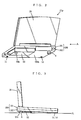
- FIGS. 1 and 2 are perspective views of a portable information processing apparatus according to the embodiment of the present invention.
- a portable information processing apparatus abbreviated as PIP apparatus PI for the sake of brevity, with two types (thin and thick) of extension devices before being installed therein is shown.
- the PIP apparatus PI with a thick type extension device being installed therein is shown.
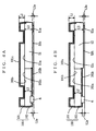
- FIGS. 4A and 4B are front sectional views of the PIP apparatus PI.
- FIG. 4A a state when a thin extension device is installed therein is shown.
- FIG. 4B a state when a thick extension device is installed therein is shown.
- the PIP apparatus PI is composed of a cabinet 100, a display unit 20, a hinge 30, and a keyboard 40 (not shown).
- the display unit 20 is detaoucheably mounted on the cabinet 100 with the hinge 30.
- the cabinet 100 is composed of an upper case 101 and a lower case 102 that are attached together on a lower surface 101b of the upper case 101 and an upper surface 102u (not shown) of the lower case 102.
- a part of the lower case 102 is removed and opened to the air for accommodating an extension device 5 as engaged with each other by connector 1b provided thereto and connector (not shown) of the extension device 5. This place is referred to as "open bay 1a" distinguishable from the conventional bay 41a.
- an FD drive 51 and a CD drive 52 are shown as examples of the extension device 5.
- the extension device 5 is not limited to the above, and may be a DVD drive or a second battery pack.
- the extension device 5 is detaoucheably engaged in the connector 10b so as to form the entire bottom surface of the cabinet together with the bottom surface 102b of the lower case 102.
- the extension device 5 is provided with a foot on its bottom surface. This foot is unique to each type of extension devices, and not variable its projection length measured from the bottom surfaces of extension device and top end thereof. This type of foot is referred to as "fixed foot”.
- this projection length defines the gap between a table and the bottom line of the PIP apparatus PI. In this sense, the projection length is referred to as "foot height or height”.
- the FD drive 51 is provided with a fixed foot 51a on its bottom surface 51b, and the CD drive 52 with a fixed foot 52a on its bottom surface 52b.
- the cabinet 100 is provided with fixed feet 1c and 1d at the front on its bottom surface 102b, and also an adjustable foot 6, at the rear thereon as opposed to the foot of the extension device 5.
- the adjustable foot 6 can be adjusted its foot height or height measure from the bottom surface 102b. According to this embodiment, the adjustable foot 6 is so constructed to be rotated for the adjusting its height in a stepless manner. Thus, the adjustable foot 6 can supports the PIP apparatus PI at the preferable horizontal level together with the fixed feet 1c, 1d, and 51a (or 51b) of the extension device 5.
- the extension device 5 is installed so that the connector thereof is engaged in the connector 1b.
- a height L1 of the upper case 101 is defined by a distance between the upper surface 101u and the lower surface 101b.
- a height L2 of the lower case 102 is defined by a distance between the upper surface 102u and the bottom surface 102b.
- a height L3 is defined by a distance between the upper surface 5u (51u, 52u) and the bottom surface 5b (51b, 52b).
- a height L2a is defined by a distance between the bottom surface 102b of the lower case 102 and the plane PL.
- a height L3a is defined by a distance between the bottom surface 5b (51b, 52b) of the extension device 5 (51, 52) and the plane PL.
- FIG. 4A the case where the FD drive 51 is accommodated as one example of a thin external device is shown.
- the adjustable foot 6 is rotated in a retractive direction for adjustment to satisfy L2 + L2a ⁇ L3 + L3a .
- the information processing apparatus 1 becomes not tilted, and placed in an approximately horizontal position.
- FIG. 4B the case where the CD drive 52 is accommodated as one example of a thick external device is shown.
- the user removes the FD drive 51 from the connector 10b in the open bay 1a, and then insert the CD drive 52 in the open bay 1a to engage.
- L2 ⁇ L3 the adjustable foot 6 is rotated in a protruding direction for adjustment to satisfy the above equation L2 + L2a ⁇ L3 + L3a .
- the front part of the cabinet 100 having the feet 1c and 1d becomes lower in height than the rear part having the adjustable foot 6 and the foot 52a of the CD drive 52. That is, the surface of the keyboard 40 is tilted toward the front, as shown in FIG. 3. Therefore, the user can easily type on the keyboard.
- the adjustable foot 6 is adjusted so as to be approximately equal in height to the foot (51a or 52a) of the extension device 5 ( L2a ⁇ L3a ).
- the foot (51a or 52a) of the extension device 5 is not necessarily required.
- the adjustable foot 6 is totally retracted into or removed from the lower case 102.
- the extension device is installed to form at least part of the bottom surface of the cabinet. Therefore, a thinner portable information processing apparatus can be achieved.
- the total thickness of the cabinet is defined by the height of the extension device installed. This can also contribute to reduction in thickness of the portable information processing apparatus.
- extension devices varied in thickness can be exchangeably accommodated. In other words, there is no need to remodel the cabinet itself for each extension device. This enhances the possibilities of the portable information processing apparatus at low cost.
- the FD drive is exemplarily described as a thin extension device, and the CD drive as a thick extension device.
- any extension device can be installed such as a DVD drive and second battery pack.
- the cabinet can be structured irrespectively of the thickness of the removable extension device installed therein. This is quite effective for reduction in thickness of the portable information processing apparatus. Furthermore, even a thicker extension device can be installed by adjusting the adjustable foot of the cabinet. This increases extensibility of the portable information processing apparatus.
- an extension device is detouheably installed on the rear bottom of the cabinet.
- the bottom surface of the extension device forms at least part of the entire bottom surface of the cabinet.
- an adjustable foot is provided on the bottom surface of the cabinet as opposed to the extension device or a foot provided on the extension device.
- the adjustable foot can be adjusted in height approximately equal to the extension device or a foot provided on the extension device.
- the adjustable foot is adjusted in height so that the entire cabinet can horizontally placed on a plane as being titled toward front.
- the adjustable foot is retracted so that the total thickness of the cabinet can be minimized.
Landscapes
- Engineering & Computer Science (AREA)
- Computer Hardware Design (AREA)
- Theoretical Computer Science (AREA)
- General Engineering & Computer Science (AREA)
- Physics & Mathematics (AREA)
- Human Computer Interaction (AREA)
- General Physics & Mathematics (AREA)
- Power Engineering (AREA)
- Mathematical Physics (AREA)
- Casings For Electric Apparatus (AREA)
Abstract
Description
- The present invention relates to portable information processing apparatuses and, more specifically, to a portable information processing apparatus capable of accommodating an extension apparatus, typically a disk drive, as a storage apparatus and battery.
- In recent years, portable information processing apparatuses, typically notebook PCs, often accommodate disk drives such as CD (Compact Disk), DVD, and FD (Floppy Disk) drives. Also, some PCs may accommodate a second battery pack to extend its drive time when carried. However, not all of these extension devices can be accommodated at once in a thin, lightweight portable information processing apparatus. Therefore, one of these devices is selected for use as required, and is installed in a bay of the portable information processing apparatus.
- With reference to FIG. 5, a portable information processingn apparatus is now described. In Fig. 5, a perspective view of the conventional portable information device viewed from the rear bottom thereof is shown. the conventional portable inforamtio apparatus PIP apparatus PIc , abbreviated to PIP apparatus PIc for the sake of brevity, includes a
cabinet 41, and adisplay unit 42 movably mounted on thecabinet 41 with ahinge 43. A U-shaped bay 41a is provided on one side of thecabinet 41 for installing anextension device 45 such as a disk drive in a detouchable manner. Theextension device 45 has a connector (not shown) for removably engaging another connector (not shown) provided inside thebay 41a of thecabinet 41. Thebay 41a is formed so that its height L5 is larger than a thickness L6 of the extension device (L5 > L6). - The installation of an
extension device 45 in the PIP apparatus PIc is now described. Specifically, in this example, an FD drive, or theextension device 45, is inserted into thebay 41a. To read data from a CD by PIP apparatus PIc, the user first operates an eject mechanism (not shown) to eject the FD drive currently installed in thebay 41a, and then insert a CD drive into the connector of thebay 41a until being engaged therewith. However, in PIP apparatus PIc, the extension device having a maximum outer dimension defines the shape ofbay 41a in size. This also defines the total thickness of the PIP apparatus PIc. Therefore, although low-profile extension devices are available with recent advanced technology, the height L5 of thebay 41a is still required to be enough to accommodate the existing bulky extension devices. Consequently, reduction in thickness of the entire portable information processing apparatus is difficult to achieve. - Therefore, an object of the present invention is to achieve reduction in thickness of a portable information processing apparatus without impairing its extensibility.
- According to a first aspect of the present invention, a portable information processing apparatus formed of a cabinet comprising an upper case and a lower case that are attached to each other, wherein an extension device is detoucheably connected to the lower case to form at least part of a bottom surface of the cabinet. Therefore, reduction in thickness of the portable information processing apparatus can be achieved.
- According to a second aspect of the present invention, in the first aspect, one of a plurality of extension devices varied in thickness can be installed as being protruding downward further than the lower surface of the upper case.
- According to a third aspect of the present invention, in the first aspect, an adjustable foot is provided on the bottom surface of the lower case, the adjustable foot capable of being adjusted in height approximately equal to any one of the extension device and the foot provided on the extension device.
- According to a fourth embodiment of the present invention, in the third aspect, the extension device and the adjustable foot are arranged rearward on the bottom surface of the cabinet as opposed to each other.
- These and other objects, features, aspects and advantages of the present invention will become more apparent from the following detailed description of the present invention when taken in conjunction with the accompanying drawings.
-
- FIG. 1 is a perspective view showing an portable information processing apparatus, according to one embodiment of the present invention, whose bay is not occupied by an extension device;
- FIG. 2 is also a perspective view similar to FIG. 1, but the bay is occupied by extension device;
- FIG. 3 is a side view showing the portable information processing apparatus of FIG. 2 placed on a plane PL;
- FIG. 4A is a front sectional view showing the portable information processing apparatus accommodating an extension device whose bottom line is aligned with that of bottom surface thereof;
- FIG. 4B is a front sectional view similar to FIG. 4A, but the bottom line of accommodated extension device is not aligned with that of bottom surface thereof; and
- FIG. 5 is a perspective view showing a conventional information processing apparatus accommodating an extension device therein.
-
- With reference to FIGS. 1, 2, 3, 4A, and 4B, a portable information processing apparatus according to one embodiment of the present invention is described below.
- FIGS. 1 and 2 are perspective views of a portable information processing apparatus according to the embodiment of the present invention. In FIG. 1, a portable information processing apparatus, abbreviated as PIP apparatus PI for the sake of brevity, with two types (thin and thick) of extension devices before being installed therein is shown. In FIG. 2, the PIP apparatus PI with a thick type extension device being installed therein is shown.
- FIGS. 4A and 4B are front sectional views of the PIP apparatus PI. In FIG. 4A, a state when a thin extension device is installed therein is shown. In FIG. 4B, a state when a thick extension device is installed therein is shown.
- As best shown in FIG. 1, the PIP apparatus PI is composed of a
cabinet 100, adisplay unit 20, ahinge 30, and a keyboard 40 (not shown). Thedisplay unit 20 is detaoucheably mounted on thecabinet 100 with thehinge 30. Thecabinet 100 is composed of anupper case 101 and alower case 102 that are attached together on alower surface 101b of theupper case 101 and anupper surface 102u (not shown) of thelower case 102. A part of thelower case 102 is removed and opened to the air for accommodating anextension device 5 as engaged with each other byconnector 1b provided thereto and connector (not shown) of theextension device 5. This place is referred to as "open bay 1a" distinguishable from theconventional bay 41a. - In FIG. 1, an
FD drive 51 and aCD drive 52 are shown as examples of theextension device 5. However, theextension device 5 is not limited to the above, and may be a DVD drive or a second battery pack. Theextension device 5 is detaoucheably engaged in the connector 10b so as to form the entire bottom surface of the cabinet together with thebottom surface 102b of thelower case 102. - The
extension device 5 is provided with a foot on its bottom surface. This foot is unique to each type of extension devices, and not variable its projection length measured from the bottom surfaces of extension device and top end thereof. This type of foot is referred to as "fixed foot". - As best shown in Fig. 3, this projection length defines the gap between a table and the bottom line of the PIP apparatus PI. In this sense, the projection length is referred to as "foot height or height".
- In FIG. 1, the FD
drive 51 is provided with a fixedfoot 51a on itsbottom surface 51b, and theCD drive 52 with a fixedfoot 52a on itsbottom surface 52b. Thecabinet 100 is provided withfixed feet bottom surface 102b, and also anadjustable foot 6, at the rear thereon as opposed to the foot of theextension device 5. - Note that the
adjustable foot 6 can be adjusted its foot height or height measure from thebottom surface 102b. According to this embodiment, theadjustable foot 6 is so constructed to be rotated for the adjusting its height in a stepless manner. Thus, theadjustable foot 6 can supports the PIP apparatus PI at the preferable horizontal level together with thefixed feet extension device 5. - The height adjustment of the above-structured portable information processing apparatus IP is described below. As typically shown in FIG. 2, the
extension device 5 is installed so that the connector thereof is engaged in theconnector 1b. - Here, as shown in FIGS. 4A and 4B, a height L1 of the
upper case 101 is defined by a distance between theupper surface 101u and thelower surface 101b. A height L2 of thelower case 102 is defined by a distance between theupper surface 102u and thebottom surface 102b. A height L3 is defined by a distance between the upper surface 5u (51u, 52u) and the bottom surface 5b (51b, 52b). - Furthermore, a height L2a is defined by a distance between the
bottom surface 102b of thelower case 102 and the plane PL. A height L3a is defined by a distance between the bottom surface 5b (51b, 52b) of the extension device 5 (51, 52) and the plane PL. - In FIG. 4A, the case where the FD drive 51 is accommodated as one example of a thin external device is shown. Here, assume L2 > L3. In this case, the
adjustable foot 6 is rotated in a retractive direction for adjustment to satisfy - In FIG. 4B, the case where the CD drive 52 is accommodated as one example of a thick external device is shown. To read data from a CD to the PIP apparatus PI, the user removes the FD drive 51 from the connector 10b in the open bay 1a, and then insert the CD drive 52 in the open bay 1a to engage. Here, assume L2 < L3. In this case, the
adjustable foot 6 is rotated in a protruding direction for adjustment to satisfy the above equationcabinet 100 having thefeet adjustable foot 6 and thefoot 52a of theCD drive 52. That is, the surface of thekeyboard 40 is tilted toward the front, as shown in FIG. 3. Therefore, the user can easily type on the keyboard. - In the case where
adjustable foot 6 is adjusted so as to be approximately equal in height to the foot (51a or 52a) of the extension device 5 ( - Note that the foot (51a or 52a) of the
extension device 5 is not necessarily required. In this case, the equation to be satisfied in both of the above first two cases (FIGS. 4A and 4B) isadjustable foot 6 is totally retracted into or removed from thelower case 102. - As such, in the present embodiment, the extension device is installed to form at least part of the bottom surface of the cabinet. Therefore, a thinner portable information processing apparatus can be achieved.
- Further, the total thickness of the cabinet is defined by the height of the extension device installed. This can also contribute to reduction in thickness of the portable information processing apparatus.
- Still further, only by adjusting the adjustable foot of the cabinet, extension devices varied in thickness can be exchangeably accommodated. In other words, there is no need to remodel the cabinet itself for each extension device. This enhances the possibilities of the portable information processing apparatus at low cost.
- In the present embodiment, the FD drive is exemplarily described as a thin extension device, and the CD drive as a thick extension device. However, any extension device can be installed such as a DVD drive and second battery pack.
- As stated above, in the present invention, the cabinet can be structured irrespectively of the thickness of the removable extension device installed therein. This is quite effective for reduction in thickness of the portable information processing apparatus. Furthermore, even a thicker extension device can be installed by adjusting the adjustable foot of the cabinet. This increases extensibility of the portable information processing apparatus.
- The followings are apparent from the above descriptions. In the portable information processing apparatus of the present invention, an extension device is detouheably installed on the rear bottom of the cabinet. The bottom surface of the extension device forms at least part of the entire bottom surface of the cabinet.
- Also, an adjustable foot is provided on the bottom surface of the cabinet as opposed to the extension device or a foot provided on the extension device. The adjustable foot can be adjusted in height approximately equal to the extension device or a foot provided on the extension device.
- If a thicker extension device is installed, it protrudes downward further than the cabinet. At this time, the adjustable foot is adjusted in height so that the entire cabinet can horizontally placed on a plane as being titled toward front. On the other hand, if a thinner extension device that is approximately equal in height to the lower case, the adjustable foot is retracted so that the total thickness of the cabinet can be minimized.
- With the above structure, reduction in thickness of the portable information processing apparatus can be achieved irrespectively of the thickness of the extension device. For increasing the portability, a thinner extension device is selected to be installed. For increasing the extendability, even a thicker extension device can be installed with adjustment in height by the adjustable foot.
- While the invention has been described in detail, the foregoing description is in all aspects illustrative and not restrictive. It is understood that numerous other modifications and variations can be devised without departing from the scope of the invention.
Claims (4)
- A portable information processing apparatus (PI) formed of a cabinet (100) comprising an upper case (101) and a lower case (102) that are attached to each other, whereinan extension device (5) is detoucheably connected to said lower case (102) to form at least part of a bottom surface (102b) of said cabinet (100).
- The portable information processing apparatus (PI) as claimed in claim 1, whereinone of a plurality of extension devices (5; 51, 52) varied in thickness can be installed as being protruding downward further than the lower surface (101b) of said upper case (101u).
- The portable information processing apparatus (PI) as claimed in claim 1, whereinan adjustable foot (6) is provided on the bottom surface (102b) of said lower case (102), said adjustable foot (6) capable of being adjusted in height approximately equal to any one of the said extension device (5) and the foot (51a, 52a) provided on said extension device (5).
- The portable information processing apparatus (PI) as claimed in claim 3, whereinsaid extension device (5) and said adjustable foot (6) are arranged rearward on the bottom surface (102b) of said cabinet (100, 102) as opposed to each other.
Applications Claiming Priority (2)
| Application Number | Priority Date | Filing Date | Title |
|---|---|---|---|
| JP25002499 | 1999-09-03 | ||
| JP25002499A JP2001075674A (en) | 1999-09-03 | 1999-09-03 | Portable information processing device |
Publications (2)
| Publication Number | Publication Date |
|---|---|
| EP1081580A1 true EP1081580A1 (en) | 2001-03-07 |
| EP1081580B1 EP1081580B1 (en) | 2017-04-19 |
Family
ID=17201716
Family Applications (1)
| Application Number | Title | Priority Date | Filing Date |
|---|---|---|---|
| EP00118255.9A Expired - Lifetime EP1081580B1 (en) | 1999-09-03 | 2000-09-04 | Portable information processing apparatus |
Country Status (3)
| Country | Link |
|---|---|
| US (1) | US6381129B1 (en) |
| EP (1) | EP1081580B1 (en) |
| JP (1) | JP2001075674A (en) |
Cited By (1)
| Publication number | Priority date | Publication date | Assignee | Title |
|---|---|---|---|---|
| WO2008086723A1 (en) * | 2007-01-04 | 2008-07-24 | Cheechun Tsang | Universal laptop computer case |
Families Citing this family (5)
| Publication number | Priority date | Publication date | Assignee | Title |
|---|---|---|---|---|
| CN100374979C (en) * | 2003-05-12 | 2008-03-12 | 富士通株式会社 | Electronic equipment |
| US7126475B2 (en) * | 2004-08-17 | 2006-10-24 | Ho Yun So | Electronic fence transmitter for self-adjusting the receiving distance |
| JP2006338189A (en) * | 2005-05-31 | 2006-12-14 | Toshiba Corp | Information processing apparatus and control method thereof |
| JP4909774B2 (en) * | 2007-03-19 | 2012-04-04 | 株式会社東芝 | Electronic devices and personal computers |
| JP5035407B2 (en) * | 2010-12-06 | 2012-09-26 | 富士通株式会社 | Electronics |
Citations (4)
| Publication number | Priority date | Publication date | Assignee | Title |
|---|---|---|---|---|
| WO1991020072A1 (en) * | 1990-06-15 | 1991-12-26 | Empruve, Inc. | System for displaying information |
| US5506749A (en) * | 1993-07-26 | 1996-04-09 | Kabushiki Kaisha Toshiba | Portable data-processing system having a removable battery pack replaceable with a second larger battery pack having a cylindrical member usable as a hand grip |
| EP0759589A2 (en) * | 1995-08-21 | 1997-02-26 | Compaq Computer Corporation | Portable computer accessory |
| US5738536A (en) * | 1993-10-29 | 1998-04-14 | Kabushiki Kaisha Toshiba | Portable electronic apparatus having a connector cover which can be housed in a case |
Family Cites Families (4)
| Publication number | Priority date | Publication date | Assignee | Title |
|---|---|---|---|---|
| US4934764A (en) * | 1989-03-31 | 1990-06-19 | Kendall Square Research Corporation | Computer system module assembly |
| WO1997010539A1 (en) * | 1995-09-15 | 1997-03-20 | Apple Computer, Inc. | Reconfigurable enclosure panel for a mobile computer |
| JPH09230961A (en) * | 1996-02-27 | 1997-09-05 | Toshiba Corp | Portable electronic devices |
| US5825616A (en) * | 1997-01-21 | 1998-10-20 | Dell Usa, L.P. | Media module locking and ejecting mechanism |
-
1999
- 1999-09-03 JP JP25002499A patent/JP2001075674A/en active Pending
-
2000
- 2000-09-01 US US09/654,264 patent/US6381129B1/en not_active Expired - Lifetime
- 2000-09-04 EP EP00118255.9A patent/EP1081580B1/en not_active Expired - Lifetime
Patent Citations (4)
| Publication number | Priority date | Publication date | Assignee | Title |
|---|---|---|---|---|
| WO1991020072A1 (en) * | 1990-06-15 | 1991-12-26 | Empruve, Inc. | System for displaying information |
| US5506749A (en) * | 1993-07-26 | 1996-04-09 | Kabushiki Kaisha Toshiba | Portable data-processing system having a removable battery pack replaceable with a second larger battery pack having a cylindrical member usable as a hand grip |
| US5738536A (en) * | 1993-10-29 | 1998-04-14 | Kabushiki Kaisha Toshiba | Portable electronic apparatus having a connector cover which can be housed in a case |
| EP0759589A2 (en) * | 1995-08-21 | 1997-02-26 | Compaq Computer Corporation | Portable computer accessory |
Cited By (1)
| Publication number | Priority date | Publication date | Assignee | Title |
|---|---|---|---|---|
| WO2008086723A1 (en) * | 2007-01-04 | 2008-07-24 | Cheechun Tsang | Universal laptop computer case |
Also Published As
| Publication number | Publication date |
|---|---|
| EP1081580B1 (en) | 2017-04-19 |
| JP2001075674A (en) | 2001-03-23 |
| US6381129B1 (en) | 2002-04-30 |
Similar Documents
| Publication | Publication Date | Title |
|---|---|---|
| KR0125094B1 (en) | Connector device | |
| US7808779B2 (en) | Rotatable dock for portable electronic devices | |
| CN101164034B (en) | Universal docking station for handheld electronic devices | |
| EP1044818B1 (en) | A printer and printer paper tray | |
| TW424189B (en) | Information processing apparatus | |
| KR100836283B1 (en) | Extended stand computer system with retractable keyboard | |
| US10372167B1 (en) | Transmission base and electronic apparatus | |
| US20150338884A1 (en) | Asymmetric Computer Tablet And Docking System | |
| US20090009955A1 (en) | Electronic apparatus having a connector connecting a disk drive | |
| US7428145B2 (en) | Electronic apparatus | |
| EP2230580B1 (en) | Adapter and portable electronic device | |
| CN100365537C (en) | Electronic equipment | |
| US20120276432A1 (en) | Battery Unit Having Case to Contain Cells | |
| US20060028791A1 (en) | Mobile computer and peripheral device arrangement | |
| EP0838747B1 (en) | Information processing apparatus having speakers | |
| CN102915081A (en) | Portable electronic device and its connection port | |
| US20040075977A1 (en) | USB memory receptacle of electronic device | |
| US20120177966A1 (en) | Electronic apparatus | |
| US20080218958A1 (en) | Computer enclosure with drive bracket | |
| EP1081580A1 (en) | Portable information processing apparatus | |
| KR20020057436A (en) | Notebook computer | |
| JPWO2004099958A1 (en) | Electronics | |
| JP2003122476A (en) | Computer device, keyboard, unit for keyboard, and bezel | |
| US7457109B2 (en) | Electronic apparatus | |
| US7724510B2 (en) | Electronic apparatus and assembly |
Legal Events
| Date | Code | Title | Description |
|---|---|---|---|
| PUAI | Public reference made under article 153(3) epc to a published international application that has entered the european phase |
Free format text: ORIGINAL CODE: 0009012 |
|
| AK | Designated contracting states |
Kind code of ref document: A1 Designated state(s): DE FR GB |
|
| AX | Request for extension of the european patent |
Free format text: AL;LT;LV;MK;RO;SI |
|
| 17P | Request for examination filed |
Effective date: 20010712 |
|
| AKX | Designation fees paid |
Free format text: DE FR GB |
|
| 17Q | First examination report despatched |
Effective date: 20020722 |
|
| RAP1 | Party data changed (applicant data changed or rights of an application transferred) |
Owner name: PANASONIC CORPORATION |
|
| RIC1 | Information provided on ipc code assigned before grant |
Ipc: G06F 1/16 20060101AFI20160914BHEP |
|
| GRAP | Despatch of communication of intention to grant a patent |
Free format text: ORIGINAL CODE: EPIDOSNIGR1 |
|
| STAA | Information on the status of an ep patent application or granted ep patent |
Free format text: STATUS: GRANT OF PATENT IS INTENDED |
|
| INTG | Intention to grant announced |
Effective date: 20161201 |
|
| GRAS | Grant fee paid |
Free format text: ORIGINAL CODE: EPIDOSNIGR3 |
|
| GRAA | (expected) grant |
Free format text: ORIGINAL CODE: 0009210 |
|
| STAA | Information on the status of an ep patent application or granted ep patent |
Free format text: STATUS: THE PATENT HAS BEEN GRANTED |
|
| AK | Designated contracting states |
Kind code of ref document: B1 Designated state(s): DE FR GB |
|
| REG | Reference to a national code |
Ref country code: GB Ref legal event code: FG4D |
|
| REG | Reference to a national code |
Ref country code: DE Ref legal event code: R096 Ref document number: 60049596 Country of ref document: DE |
|
| REG | Reference to a national code |
Ref country code: FR Ref legal event code: PLFP Year of fee payment: 18 |
|
| REG | Reference to a national code |
Ref country code: DE Ref legal event code: R097 Ref document number: 60049596 Country of ref document: DE |
|
| PLBE | No opposition filed within time limit |
Free format text: ORIGINAL CODE: 0009261 |
|
| STAA | Information on the status of an ep patent application or granted ep patent |
Free format text: STATUS: NO OPPOSITION FILED WITHIN TIME LIMIT |
|
| 26N | No opposition filed |
Effective date: 20180122 |
|
| REG | Reference to a national code |
Ref country code: FR Ref legal event code: PLFP Year of fee payment: 19 |
|
| PGFP | Annual fee paid to national office [announced via postgrant information from national office to epo] |
Ref country code: FR Payment date: 20190925 Year of fee payment: 20 Ref country code: DE Payment date: 20190918 Year of fee payment: 20 |
|
| PGFP | Annual fee paid to national office [announced via postgrant information from national office to epo] |
Ref country code: GB Payment date: 20190920 Year of fee payment: 20 |
|
| REG | Reference to a national code |
Ref country code: DE Ref legal event code: R071 Ref document number: 60049596 Country of ref document: DE |
|
| REG | Reference to a national code |
Ref country code: GB Ref legal event code: PE20 Expiry date: 20200903 |
|
| PG25 | Lapsed in a contracting state [announced via postgrant information from national office to epo] |
Ref country code: GB Free format text: LAPSE BECAUSE OF EXPIRATION OF PROTECTION Effective date: 20200903 |