EP1081561A2 - Image banding reduction method for use in an indirect transfer type image forming apparatus - Google Patents
Image banding reduction method for use in an indirect transfer type image forming apparatus Download PDFInfo
- Publication number
- EP1081561A2 EP1081561A2 EP00307478A EP00307478A EP1081561A2 EP 1081561 A2 EP1081561 A2 EP 1081561A2 EP 00307478 A EP00307478 A EP 00307478A EP 00307478 A EP00307478 A EP 00307478A EP 1081561 A2 EP1081561 A2 EP 1081561A2
- Authority
- EP
- European Patent Office
- Prior art keywords
- paper
- transfer
- roller
- transfer nip
- fusing
- Prior art date
- Legal status (The legal status is an assumption and is not a legal conclusion. Google has not performed a legal analysis and makes no representation as to the accuracy of the status listed.)
- Granted
Links
Images



Classifications
-
- G—PHYSICS
- G03—PHOTOGRAPHY; CINEMATOGRAPHY; ANALOGOUS TECHNIQUES USING WAVES OTHER THAN OPTICAL WAVES; ELECTROGRAPHY; HOLOGRAPHY
- G03G—ELECTROGRAPHY; ELECTROPHOTOGRAPHY; MAGNETOGRAPHY
- G03G15/00—Apparatus for electrographic processes using a charge pattern
- G03G15/20—Apparatus for electrographic processes using a charge pattern for fixing, e.g. by using heat
- G03G15/2003—Apparatus for electrographic processes using a charge pattern for fixing, e.g. by using heat using heat
- G03G15/2014—Apparatus for electrographic processes using a charge pattern for fixing, e.g. by using heat using heat using contact heat
- G03G15/2064—Apparatus for electrographic processes using a charge pattern for fixing, e.g. by using heat using heat using contact heat combined with pressure
-
- G—PHYSICS
- G03—PHOTOGRAPHY; CINEMATOGRAPHY; ANALOGOUS TECHNIQUES USING WAVES OTHER THAN OPTICAL WAVES; ELECTROGRAPHY; HOLOGRAPHY
- G03G—ELECTROGRAPHY; ELECTROPHOTOGRAPHY; MAGNETOGRAPHY
- G03G15/00—Apparatus for electrographic processes using a charge pattern
- G03G15/14—Apparatus for electrographic processes using a charge pattern for transferring a pattern to a second base
- G03G15/16—Apparatus for electrographic processes using a charge pattern for transferring a pattern to a second base of a toner pattern, e.g. a powder pattern, e.g. magnetic transfer
- G03G15/1605—Apparatus for electrographic processes using a charge pattern for transferring a pattern to a second base of a toner pattern, e.g. a powder pattern, e.g. magnetic transfer using at least one intermediate support
-
- G—PHYSICS
- G03—PHOTOGRAPHY; CINEMATOGRAPHY; ANALOGOUS TECHNIQUES USING WAVES OTHER THAN OPTICAL WAVES; ELECTROGRAPHY; HOLOGRAPHY
- G03G—ELECTROGRAPHY; ELECTROPHOTOGRAPHY; MAGNETOGRAPHY
- G03G2215/00—Apparatus for electrophotographic processes
- G03G2215/16—Transferring device, details
- G03G2215/1676—Simultaneous toner image transfer and fixing
- G03G2215/168—Simultaneous toner image transfer and fixing at the first transfer point
- G03G2215/1685—Simultaneous toner image transfer and fixing at the first transfer point using heat
-
- G—PHYSICS
- G03—PHOTOGRAPHY; CINEMATOGRAPHY; ANALOGOUS TECHNIQUES USING WAVES OTHER THAN OPTICAL WAVES; ELECTROGRAPHY; HOLOGRAPHY
- G03G—ELECTROGRAPHY; ELECTROPHOTOGRAPHY; MAGNETOGRAPHY
- G03G2215/00—Apparatus for electrophotographic processes
- G03G2215/16—Transferring device, details
- G03G2215/1676—Simultaneous toner image transfer and fixing
- G03G2215/1695—Simultaneous toner image transfer and fixing at the second or higher order transfer point
-
- G—PHYSICS
- G03—PHOTOGRAPHY; CINEMATOGRAPHY; ANALOGOUS TECHNIQUES USING WAVES OTHER THAN OPTICAL WAVES; ELECTROGRAPHY; HOLOGRAPHY
- G03G—ELECTROGRAPHY; ELECTROPHOTOGRAPHY; MAGNETOGRAPHY
- G03G2215/00—Apparatus for electrophotographic processes
- G03G2215/20—Details of the fixing device or porcess
- G03G2215/2003—Structural features of the fixing device
Definitions
- the present invention relates to a method for reducing image banding, the method being for use with a photoreceptor medium of an indirect transfer type image forming apparatus.
- a change in the speed of a photoreceptor web can be maintained to a minimum when an image formed on the photoreceptor web is indirectly transferred to a sheet of paper transferring between the fusing roller and the transfer roller.
- an indirect transfer type image forming apparatus such as a color laser printer or a photocopier is arranged to print a desired image by developing an electrostatic latent image formed on a photoreceptor medium such as a photoreceptor web or a photoreceptor drum with a developer having a predetermined color and transferring the developed image to a sheet of paper.
- an indirect transfer type image forming apparatus wherein an electrostatic latent image is formed on a surface of a photoreceptor web 10 circulating along an endless path, by an electrostatic latent image forming device such as a laser scanning unit (LSU) 32.
- a toner image is formed on the surface of the photoreceptor web 10 by developing the electrostatic latent image with a developing unit 20.
- the image forming apparatus includes a transfer unit 30 having a transfer roller 22 and a fusing roller 24 to transfer the toner image formed on the photoreceptor web 10 to a sheet of paper 26.
- Figure 2 is a graph showing changes in the speed of the photoreceptor web 10 at the moment when the leading edge E 1 of paper enters the transfer nip N t or a trailing edge E t thereof is exhausted from the transfer nip N t in a conventional indirect transfer type image forming apparatus, and a banding phenomenon of an image according to the above change, through experiments.
- the vertical axis indicates changes ( ⁇ v) in the speed of the photoreceptor web with respect to a regular speed (v) thereof which is calculated in percentage.
- a positive value means acceleration and a negative value means deceleration in the speed of photoreceptor web 10.
- the horizontal axis indicates time.
- a portion A is a moment when the leading edge E 1 enters the transfer nip N t and a portion B is a moment when a trailing edge E t of the paper is exhausted from the transfer nip N t . That is, the speed of the photoreceptor web 10 changes due to impact generated when the paper 26 enters and is exhausted from the transfer nip N t .
- the factor possibly illaffecting the constancy of the photoreceptor web driven by a driving roller is the thickness of the paper itself periodically entering between the transfer roller and the fusing roller, and this actually causes a considerable speed change of the photoreceptor web.
- the lower portion of the drawing shows an example of an image printed on a sheet of paper affected by changes in the speed of the photoreceptor web.
- the moment when the leading edge of the paper 26 enters between the transfer roller 22 and the fusing roller 24 is ⁇ t 1
- the time for maintaining a constant speed after the paper enters is ⁇ t 2
- the moment when the trailing edge of the paper is exhausted between the transfer roller 22 and the fusing roller 24 is ⁇ t 3 .
- the type of banding generated to the image that is, the change in width ⁇ L of banding or concentration of the image is closely related to the change in speed of the photoreceptor web 10.
- the change of the concentration of the image depends on the amount of the speed change of the photoreceptor web and the width of banding ⁇ L depends on the duration of the change of the speed ⁇ t.
- ⁇ is the speed of the photoreceptor web.
- Preferred embodiments of the invention aim to minimise speed changes at the point where the paper arrives at or is exhausted from the transfer nip, so that a superior print quality can be guaranteed.
- an image banding reduction method of a photoreceptor medium of an indirect transfer type image forming apparatus for preventing banding occurring by a change in the speed of the photoreceptor medium generated when the leading edge and trailing edge of a sheet of paper pass through a transfer nip formed between a transfer roller and a fusing roller, which is achieved by (A) separating the transfer roller and the fusing roller a predetermined distance from each other before the leading edge of paper enters the transfer nip, (B) approximating the transfer roller and the fusing roll after the leading edge of paper has entered the transfer nip, and maintaining the transfer nip in a normal state, and (C) separating again the transfer roller and the fusing roller a predetermined distance from each other before the trailing edge of paper is exhausted from the transfer nip.
- an image banding reduction method of a photoreceptor medium of an indirect transfer type image forming apparatus for preventing banding occurring by a change in the speed of the photoreceptor medium generated when the leading edge and trailing edge of a sheet of paper pass through a transfer nip formed between a transfer roller and a fusing roller, which is achieved by (A) reducing a pressing force applied between the transfer roller and the fusing roller less than the pressing force in a normal state, before the leading edge of paper enters the transfer nip, (B) restoring the pressing force applied between the transfer roller and the fusing roller to the normal state after the leading edge of paper has entered the transfer nip, and (C) reducing the pressing force applied between the transfer roller and the fusing roller less than the pressing force in the normal state, before the trailing edge of paper is exhausted from the transfer nip.
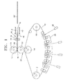
- FIG. 1 is a view showing the structure of a general indirect transfer type image forming apparatus.
- the image forming apparatus includes a photoreceptor medium 10 such as a photoreceptor web, circulating an endless path being supported by a plurality of rollers 12, 14 and 16, a development unit 20 for developing with developer an electrostatic latent image area formed on the photoreceptor medium 10, a transfer unit 30 for transferring a toner image developed on the surface of the photoreceptor web to a sheet of paper P, and a paper supply unit 40 for supplying paper P toward the transfer unit 30.
- Reference numeral 32 denotes a laser scanning unit.
- the development unit 20, separated from the photoreceptor medium 10 at the initial stage begins an image forming process as the development unit 20, a drying unit (not shown) and the transfer unit 30 are pressed to the photoreceptor medium 10 by a predetermined pressure.
- the transfer unit 30 includes a transfer roller 22, rotating at a predetermined speed in close contact with the photoreceptor medium 10, for transferring a toner image formed on the photoreceptor medium 10 to the paper P to print the image, and a fusing roller 24, rotating in close contact with the transfer roller 22, for pressing the paper P toward the transfer roller 22 to fuse and fix the toner image on the paper P.
- the fusing roller 24 and the transfer roller 22 are disposed to be capable of being separated a predetermined distance from the transfer roller 22 and the photoreceptor medium 10, respectively.
- the applicant has developed an image forming apparatus in which a separation between the transfer roller 22 and the fusing roller 24 is possible.
- the image forming apparatus includes an assembling/disassembling means for selectively assembling and disassembling the photoreceptor web 10, the transfer roller 22 and the fusing roller 24.
- the transfer roller 22 is supported by a first plate 50 and a second plate 53 supporting the fusing roller 24 is rotatably coupled to a rotation shaft 55 at one side of the first plate 50.
- the first plate 50 and the second plate 53 are elastically biased by an elastic means 70 at the other side facing the rotation shaft 55 in a direction that they approach each other.
- a second cam 60 closely contacting a cam protrusion 53 provide at the second plate 53 is rotatably installed at the first plate 50.
- the second cam 60 is dynamically connected to the first cam 75 via first and second intermediate gears 66 and 68 supported by first and second engagement levers 62 and 64.
- first cam 75 rotates
- second cam 60 rotates by the first and second intermediate gears 66 and 68.
- the cam protrusion 57 of the second plate 53 is lifted.
- the second plate 53 rotates counterclockwise with respect to the drawing sheet around the rotation shaft 55.
- the fusing roller 24 supported by the second plate 53 is separated from the transfer roller 22, as shown in Figure 3B.
- the first cam 75 is rotated in the oppose direction, the force applied to the first cam 75 is released and the second plate 53 returns to the original position by a restoration force of the elastic means 70.
- a paper supply path 42 is provided to the paper supply unit 40 and a pair of registration rollers 44 are installed on the paper supply path 42.
- a registration nip N r is formed at a portion where the registration rollers 44 are engaged with each other.
- the registration rollers 44 are arranged to align the paper P before the paper P is supplied to the transfer nip N t formed between the transfer roller 22 and the fusing roller 24.
- the paper supply unit 40 provides a paper detection sensor 46 to detect whether the paper P supplied along the paper supply path 42 arrives at the registration nip N r or is exhausted therefrom.
- the paper detection sensor 46 detects whether the paper is jammed by checking the time the leading edge of the paper P arrives at the registration roller 44. Also, the paper detection sensor 46 matches the time when the toner image transferred to the transfer roller arrives at the transfer nip N t , with the time when the paper arrives at the transfer nip N t . Thus, when the distance between the transfer nip N t and the registration roller 44 is set and the rotation speed of the registration roller 44 are known, the timing of elevating the fusing roller 24 can be controlled in tune with the timing of arriving at the transfer nip N t of the leading end of the paper P.
- the paper detection sensor 46 is used for anticipating the time the paper P enters the transfer nip N t from the point when the leading edge E 1 of the paper P passes the registration roller 44, and the time the paper P is exhausted therefrom. That is, the paper detection sensor 46 accurately matches the timing of elevating of the fusing roller 24 with the time the leading edge E 1 and the trailing edge E t of the paper P passes through the transfer nip N t .
- Figure 4 is a flow chart for explaining a banding reduction method of a photoreceptor medium of an indirect transfer type image forming apparatus according to the preferred embodiment of the present invention
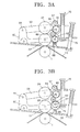
- Figures 5A through 5C are views showing a transfer unit portion for explaining the banding reduction method.
- the structural elements having the same reference numerals as those indicated in Figure 1 are the members having the same functions.
- step S110 and referring to Figure 5A the fusing roller 24 is lifted to be separated from the transfer roller 22, before the leading edge E 1 of the paper P enters the transfer nip N t by the registration roller 44 rotating at a constant speed.
- the registration roller 44 is driven by a controller (not shown) according to the timing control.
- the fusing roller 24 is slightly lifted by driving a cam driving motor (not shown).
- the lift of the fusing roller 24 may minimize the change in circulating speed of the photoreceptor medium 10 due to the leading edge E 1 of the paper P. This is to minimize the impact generated when the paper P enters the transfer nip N t .
- step S120 and referring to Figure 5B after the leading edge E 1 of the paper P passes through the transfer nip N t , the lifted fusing roller 24 is lowered and the transfer nip N t is returned to the normal state. That is, the fusing roller 24 is rotated in a direction in which the cam driving motor applies a pressing force and maintains a normal pressing state in which a normal image forming operation is performed. The image transferred to the transfer roller 22 is transferred again to the paper P and adheres to the paper P by the fusing roller 24.
- step S130 and referring to Figure 5C the transfer roller 22 and the fusing roller 24 are separated from each other by lifting the fusing roller 24 a predetermined distance before the trailing edge E t of the paper P is exhausted from the transfer nip N t . That is, by checking the size of the paper P and the driving time, the pressing force of the fusing roller 24 is released just before the trailing edge E t of the paper P passes through the transfer nip N t .
- the separation distance is the same as that of separation occurring when the leading edge E 1 passes through the transfer nip N t .
- the two rollers 22 and 24 can be in contact with each other in a state in which the pressing force is reduced.
- a pressing force between the transfer roller 22 and the fusing roller 24 is maintained at about 70 kgf.
- the degree of reduction of the pressing force may vary according to the thickness of the paper P.
- the thickness of paper used for typical image forming apparatuses is restricted to particular values.
- the allowed thickness of paper is about 80 ⁇ m - 230 ⁇ m and the degree that the pressing force is reduced can be allowed step by step according to the thickness of paper.
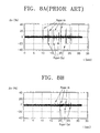
- Figure 8A is a graph showing the changes in the speed of the photoreceptor web with respect to time according to the conventional technology. That is, the banding of an image when a sheet of paper enters (paper-in) and is drawn (paper-out) is shown, and both changes of speed of the photoreceptor web occurring during the paper-in and paper-out are simultaneously shown. Such banding of an image is repeated when sheets of paper are continuously fed.
- Figure 8B is a graph showing the changes in the speed of the photoreceptor web with respect to time according to a preferred embodiment of the present invention. It can be seen from the drawing that the speed change of a photoreceptor medium when the paper is inserted and exhausted is remarkably reduced compared to the conventional technology.
- the above banding reduction method can be applied to all image forming apparatuses of a type in which paper is exchanged during the transfer operation of the transfer roller adjacent to the photoreceptor medium while image formation continues.
- the banding reduction method of a photoreceptor medium of an indirect transfer type image forming apparatus has the following merits.
Landscapes
- Physics & Mathematics (AREA)
- General Physics & Mathematics (AREA)
- Electrostatic Charge, Transfer And Separation In Electrography (AREA)
- Fixing For Electrophotography (AREA)
- Control Or Security For Electrophotography (AREA)
Abstract
Description
Claims (7)
- An image banding reduction method for use in an indirect transfer type image forming apparatus having a transfer nip (Nt) formed between a transfer roller (22) and a fusing roller (24), the method comprising the steps of:(a) separating the transfer roller (22) and the fusing roller (24) a predetermined distance from each other before a leading edge (E1) of a sheet of paper (P) enters the transfer nip (Nt) ;(b) approximating the transfer roller (22) and the fusing roller (24) after the leading edge (E1) of paper (P) has entered the transfer nip (Nt), and maintaining the transfer nip (Nt) in a normal state; and(c) separating again the transfer roller (22) and the fusing roller (24) a predetermined distance from each other before the trailing edge (Et) of paper is exhausted from the transfer nip (Nt) .
- The method as claimed in claim 1, wherein a paper detecting sensor (46) is disposed to be separated a predetermined distance from the transfer nip (Nt), and the time to separate the transfer roller (22) and the fusing roller (24) from each other is determined by the paper detecting sensor (46) by anticipating the moment when the leading edge of paper arrives at the transfer nip and the moment when the trailing edge of paper is exhausted from the transfer nip.
- The method as claimed in either claim 1 or claim 2, wherein the steps (a), (b), and (c) are applied to a case in which the thickness of the paper is in the range between 80µm to 230µm.
- An image banding reduction method for use in an indirect transfer type image forming apparatus having a transfer nip (Nt) formed between a transfer roller (22) and a fusing roller (24), the method comprising the steps of:(a) reducing a pressing force (F2) applied between the transfer roller (22) and the fusing roller (24) less than the pressing force (F1) in a normal state, before a leading edge (E1) of paper (P) enters the transfer nip (Nt);(b) restoring the pressing force (F1) applied between the transfer roller (22) and the fusing roller (24) to the normal state after the leading edge of paper has entered the transfer nip; and(c) reducing the pressing force (F2) applied between the transfer roller (22) and the fusing roller (24) less than the pressing force (F1) in the normal state, before the trailing edge of paper is exhausted from the transfer nip.
- The method as claimed in claim 4, wherein a paper detecting sensor (46) is disposed to be separated a predetermined distance from the transfer nip, and the time to reduce the pressing force (F1,F2) applied between the transfer roller (22) and the fusing roller (24) is determined by the paper detecting sensor by anticipating the moment when the leading edge (E1) of paper arrives at the transfer nip (Nt) and the moment when the trailing edge (Et) of paper is exhausted from the transfer nip (Nt) .
- The method as claimed in either claim 4 or claim 5, wherein the steps (a), (b), and (c) are applied to a case in which the thickness of the paper is in the range between 80µm to 230µm.
- The method as claimed in claim 6, wherein the pressing force (F1,F2) applied between the transfer roller (22) and the fusing roller (24) is selectively adjusted according to the thickness of the paper (P).
Applications Claiming Priority (2)
| Application Number | Priority Date | Filing Date | Title |
|---|---|---|---|
| KR9936849 | 1999-09-01 | ||
| KR1019990036849A KR100338760B1 (en) | 1999-09-01 | 1999-09-01 | Method for mitigating image banding of photoreceptor of indirect transfer type image forming apparatus |
Publications (3)
| Publication Number | Publication Date |
|---|---|
| EP1081561A2 true EP1081561A2 (en) | 2001-03-07 |
| EP1081561A3 EP1081561A3 (en) | 2002-01-30 |
| EP1081561B1 EP1081561B1 (en) | 2004-05-06 |
Family
ID=19609631
Family Applications (1)
| Application Number | Title | Priority Date | Filing Date |
|---|---|---|---|
| EP00307478A Expired - Lifetime EP1081561B1 (en) | 1999-09-01 | 2000-08-31 | Image banding reduction method for use in an indirect transfer type image forming apparatus |
Country Status (6)
| Country | Link |
|---|---|
| US (1) | US6343203B1 (en) |
| EP (1) | EP1081561B1 (en) |
| JP (1) | JP2001092332A (en) |
| KR (1) | KR100338760B1 (en) |
| CN (1) | CN1122198C (en) |
| DE (1) | DE60010390T2 (en) |
Cited By (1)
| Publication number | Priority date | Publication date | Assignee | Title |
|---|---|---|---|---|
| EP1596255A1 (en) * | 2004-03-09 | 2005-11-16 | Seiko Epson Corporation | Image forming apparatus with developer cartridges containing toner of the same colour |
Families Citing this family (19)
| Publication number | Priority date | Publication date | Assignee | Title |
|---|---|---|---|---|
| US7065308B2 (en) * | 2003-11-24 | 2006-06-20 | Xerox Corporation | Transfer roll engagement method for minimizing media induced motion quality disturbances |
| US7260338B2 (en) * | 2004-03-24 | 2007-08-21 | Eastman Kodak Company | Apparatus and process for fuser control |
| US7242884B2 (en) * | 2004-03-24 | 2007-07-10 | Eastman Kodak Company | Apparatus and process for fuser control |
| JP4741891B2 (en) * | 2005-06-29 | 2011-08-10 | 株式会社リコー | Transfer device and image forming apparatus |
| JP4994876B2 (en) * | 2006-05-19 | 2012-08-08 | 株式会社リコー | Image forming apparatus |
| JP5084228B2 (en) * | 2006-11-10 | 2012-11-28 | キヤノン株式会社 | Image forming apparatus |
| JP5121223B2 (en) * | 2006-12-19 | 2013-01-16 | キヤノン株式会社 | Recording apparatus and recording method |
| JP5015666B2 (en) * | 2007-06-04 | 2012-08-29 | 株式会社リコー | Image forming apparatus |
| JP5090827B2 (en) * | 2007-09-03 | 2012-12-05 | 株式会社リコー | Image forming apparatus |
| US8422037B2 (en) | 2008-02-19 | 2013-04-16 | Ricoh Company, Ltd. | Image forming apparatus |
| JP2010139952A (en) * | 2008-12-15 | 2010-06-24 | Fuji Xerox Co Ltd | Image forming apparatus and program |
| JP5392486B2 (en) * | 2009-10-19 | 2014-01-22 | コニカミノルタ株式会社 | Image forming apparatus and control method thereof |
| JP5832198B2 (en) * | 2011-08-19 | 2015-12-16 | キヤノン株式会社 | Sheet compression apparatus and image forming apparatus |
| JP5810800B2 (en) * | 2011-09-27 | 2015-11-11 | コニカミノルタ株式会社 | Image forming apparatus |
| JP5949433B2 (en) * | 2012-10-22 | 2016-07-06 | 富士ゼロックス株式会社 | Transfer device and image forming apparatus |
| JP6171552B2 (en) * | 2013-05-17 | 2017-08-02 | 株式会社リコー | Transfer device and image forming apparatus |
| JP6498039B2 (en) * | 2015-05-28 | 2019-04-10 | キヤノン株式会社 | Fixing device |
| JP6900718B2 (en) * | 2017-03-15 | 2021-07-07 | ブラザー工業株式会社 | Fixing device |
| JP7753838B2 (en) * | 2021-12-02 | 2025-10-15 | コニカミノルタ株式会社 | Image forming device |
Family Cites Families (5)
| Publication number | Priority date | Publication date | Assignee | Title |
|---|---|---|---|---|
| JPH01288882A (en) * | 1988-05-16 | 1989-11-21 | Canon Inc | Image forming device |
| JPH08324841A (en) * | 1995-06-01 | 1996-12-10 | Canon Inc | Image forming device |
| US5926680A (en) * | 1996-07-16 | 1999-07-20 | Asahi Kogaku Kogyo Kabushiki Kaisha | Fixing unit |
| US5799232A (en) * | 1996-10-07 | 1998-08-25 | T/R Systems | Friction drive for an electrophotographic print engine |
| KR100234328B1 (en) * | 1997-08-28 | 1999-12-15 | 윤종용 | Roller spacer for laser printer |
-
1999
- 1999-09-01 KR KR1019990036849A patent/KR100338760B1/en not_active Expired - Fee Related
-
2000
- 2000-08-31 JP JP2000264066A patent/JP2001092332A/en active Pending
- 2000-08-31 EP EP00307478A patent/EP1081561B1/en not_active Expired - Lifetime
- 2000-08-31 DE DE60010390T patent/DE60010390T2/en not_active Expired - Fee Related
- 2000-09-01 CN CN00131307A patent/CN1122198C/en not_active Expired - Fee Related
- 2000-09-01 US US09/654,170 patent/US6343203B1/en not_active Expired - Fee Related
Cited By (2)
| Publication number | Priority date | Publication date | Assignee | Title |
|---|---|---|---|---|
| EP1596255A1 (en) * | 2004-03-09 | 2005-11-16 | Seiko Epson Corporation | Image forming apparatus with developer cartridges containing toner of the same colour |
| US7242872B2 (en) | 2004-03-09 | 2007-07-10 | Seiko Epson Corporation | Image forming apparatus with changeover control for development cartridges |
Also Published As
| Publication number | Publication date |
|---|---|
| KR20010025815A (en) | 2001-04-06 |
| KR100338760B1 (en) | 2002-05-30 |
| CN1122198C (en) | 2003-09-24 |
| DE60010390D1 (en) | 2004-06-09 |
| DE60010390T2 (en) | 2005-05-04 |
| JP2001092332A (en) | 2001-04-06 |
| CN1286417A (en) | 2001-03-07 |
| EP1081561A3 (en) | 2002-01-30 |
| EP1081561B1 (en) | 2004-05-06 |
| US6343203B1 (en) | 2002-01-29 |
Similar Documents
| Publication | Publication Date | Title |
|---|---|---|
| EP1081561B1 (en) | Image banding reduction method for use in an indirect transfer type image forming apparatus | |
| US7798491B2 (en) | Sheet conveying apparatus and image forming apparatus | |
| KR100341323B1 (en) | Method for controllig paper feed of a liquid electrophotographic color printer | |
| EP3121654B1 (en) | Image forming apparatus for controlling recording medium conveyance | |
| US20110204561A1 (en) | Sheet conveying apparatus and image forming apparatus | |
| US20080232878A1 (en) | Image forming apparatus | |
| KR100655931B1 (en) | Recording medium conveying apparatus and recording medium conveying method | |
| KR100565094B1 (en) | Paper detection device and image forming device having same | |
| CN101295151A (en) | image forming device | |
| EP1156394A2 (en) | Liquid electrophotographic printing apparatus | |
| JP4612836B2 (en) | Sheet detecting apparatus and image forming apparatus | |
| KR100636234B1 (en) | Image forming apparatus and discharge roller reduction method including discharge roller reduction means | |
| JPH08262824A (en) | Recording paper jam detector | |
| JP3782493B2 (en) | Sheet conveying apparatus and sheet processing apparatus | |
| KR100354066B1 (en) | Apparatus for detecting transfer jam of a liquid electrophotographic color printer | |
| JPH05297763A (en) | Electrophotographic device | |
| JP4072796B2 (en) | Image forming apparatus | |
| JP4143208B2 (en) | Sheet feeding apparatus and image forming apparatus provided with the apparatus | |
| JP3591976B2 (en) | Image forming device | |
| JPH0940209A (en) | Conveying roller pair device and image forming apparatus | |
| JP3674197B2 (en) | Side registration device | |
| JP4027260B2 (en) | Paper discharge device, image forming device | |
| JPH10254204A (en) | Imaging device | |
| JPH09152802A (en) | Electrophotographic printer | |
| JPH08234616A (en) | Image forming device |
Legal Events
| Date | Code | Title | Description |
|---|---|---|---|
| PUAI | Public reference made under article 153(3) epc to a published international application that has entered the european phase |
Free format text: ORIGINAL CODE: 0009012 |
|
| 17P | Request for examination filed |
Effective date: 20000912 |
|
| AK | Designated contracting states |
Kind code of ref document: A2 Designated state(s): AT BE CH CY DE DK ES FI FR GB GR IE IT LI LU MC NL PT SE Kind code of ref document: A2 Designated state(s): DE FR GB |
|
| AX | Request for extension of the european patent |
Free format text: AL;LT;LV;MK;RO;SI |
|
| PUAL | Search report despatched |
Free format text: ORIGINAL CODE: 0009013 |
|
| AK | Designated contracting states |
Kind code of ref document: A3 Designated state(s): AT BE CH CY DE DK ES FI FR GB GR IE IT LI LU MC NL PT SE |
|
| AX | Request for extension of the european patent |
Free format text: AL;LT;LV;MK;RO;SI |
|
| AKX | Designation fees paid |
Free format text: DE FR GB |
|
| GRAP | Despatch of communication of intention to grant a patent |
Free format text: ORIGINAL CODE: EPIDOSNIGR1 |
|
| GRAS | Grant fee paid |
Free format text: ORIGINAL CODE: EPIDOSNIGR3 |
|
| GRAA | (expected) grant |
Free format text: ORIGINAL CODE: 0009210 |
|
| AK | Designated contracting states |
Kind code of ref document: B1 Designated state(s): DE FR GB |
|
| REG | Reference to a national code |
Ref country code: GB Ref legal event code: FG4D |
|
| REF | Corresponds to: |
Ref document number: 60010390 Country of ref document: DE Date of ref document: 20040609 Kind code of ref document: P |
|
| REG | Reference to a national code |
Ref country code: IE Ref legal event code: FG4D |
|
| ET | Fr: translation filed | ||
| PLBE | No opposition filed within time limit |
Free format text: ORIGINAL CODE: 0009261 |
|
| STAA | Information on the status of an ep patent application or granted ep patent |
Free format text: STATUS: NO OPPOSITION FILED WITHIN TIME LIMIT |
|
| 26N | No opposition filed |
Effective date: 20050208 |
|
| REG | Reference to a national code |
Ref country code: IE Ref legal event code: MM4A |
|
| PGFP | Annual fee paid to national office [announced via postgrant information from national office to epo] |
Ref country code: DE Payment date: 20080912 Year of fee payment: 9 |
|
| PGFP | Annual fee paid to national office [announced via postgrant information from national office to epo] |
Ref country code: FR Payment date: 20080818 Year of fee payment: 9 |
|
| PGFP | Annual fee paid to national office [announced via postgrant information from national office to epo] |
Ref country code: GB Payment date: 20080903 Year of fee payment: 9 |
|
| GBPC | Gb: european patent ceased through non-payment of renewal fee |
Effective date: 20090831 |
|
| REG | Reference to a national code |
Ref country code: FR Ref legal event code: ST Effective date: 20100430 |
|
| PG25 | Lapsed in a contracting state [announced via postgrant information from national office to epo] |
Ref country code: DE Free format text: LAPSE BECAUSE OF NON-PAYMENT OF DUE FEES Effective date: 20100302 Ref country code: FR Free format text: LAPSE BECAUSE OF NON-PAYMENT OF DUE FEES Effective date: 20090831 |
|
| PG25 | Lapsed in a contracting state [announced via postgrant information from national office to epo] |
Ref country code: GB Free format text: LAPSE BECAUSE OF NON-PAYMENT OF DUE FEES Effective date: 20090831 |
|
| REG | Reference to a national code |
Ref country code: GB Ref legal event code: 732E Free format text: REGISTERED BETWEEN 20170406 AND 20170412 |
|
| REG | Reference to a national code |
Ref country code: FR Ref legal event code: TP Owner name: S-PRINTING SOLUTION CO., LTD., KR Effective date: 20170912 |