EP1081384A2 - Scroll compressor with a discharge valve - Google Patents
Scroll compressor with a discharge valve Download PDFInfo
- Publication number
- EP1081384A2 EP1081384A2 EP00119198A EP00119198A EP1081384A2 EP 1081384 A2 EP1081384 A2 EP 1081384A2 EP 00119198 A EP00119198 A EP 00119198A EP 00119198 A EP00119198 A EP 00119198A EP 1081384 A2 EP1081384 A2 EP 1081384A2
- Authority
- EP
- European Patent Office
- Prior art keywords
- scroll
- movable
- base plate
- discharge port
- Prior art date
- Legal status (The legal status is an assumption and is not a legal conclusion. Google has not performed a legal analysis and makes no representation as to the accuracy of the status listed.)
- Withdrawn
Links
- 238000007599 discharging Methods 0.000 claims 1
- 239000003507 refrigerant Substances 0.000 description 8
- 230000007423 decrease Effects 0.000 description 5
- 230000006835 compression Effects 0.000 description 4
- 238000007906 compression Methods 0.000 description 4
- 230000004308 accommodation Effects 0.000 description 2
- 230000002093 peripheral effect Effects 0.000 description 2
- 238000009434 installation Methods 0.000 description 1
Images




Classifications
-
- F—MECHANICAL ENGINEERING; LIGHTING; HEATING; WEAPONS; BLASTING
- F04—POSITIVE - DISPLACEMENT MACHINES FOR LIQUIDS; PUMPS FOR LIQUIDS OR ELASTIC FLUIDS
- F04C—ROTARY-PISTON, OR OSCILLATING-PISTON, POSITIVE-DISPLACEMENT MACHINES FOR LIQUIDS; ROTARY-PISTON, OR OSCILLATING-PISTON, POSITIVE-DISPLACEMENT PUMPS
- F04C29/00—Component parts, details or accessories of pumps or pumping installations, not provided for in groups F04C18/00 - F04C28/00
- F04C29/12—Arrangements for admission or discharge of the working fluid, e.g. constructional features of the inlet or outlet
- F04C29/124—Arrangements for admission or discharge of the working fluid, e.g. constructional features of the inlet or outlet with inlet and outlet valves specially adapted for rotary or oscillating piston pumps
- F04C29/126—Arrangements for admission or discharge of the working fluid, e.g. constructional features of the inlet or outlet with inlet and outlet valves specially adapted for rotary or oscillating piston pumps of the non-return type
-
- F—MECHANICAL ENGINEERING; LIGHTING; HEATING; WEAPONS; BLASTING
- F04—POSITIVE - DISPLACEMENT MACHINES FOR LIQUIDS; PUMPS FOR LIQUIDS OR ELASTIC FLUIDS
- F04C—ROTARY-PISTON, OR OSCILLATING-PISTON, POSITIVE-DISPLACEMENT MACHINES FOR LIQUIDS; ROTARY-PISTON, OR OSCILLATING-PISTON, POSITIVE-DISPLACEMENT PUMPS
- F04C18/00—Rotary-piston pumps specially adapted for elastic fluids
- F04C18/02—Rotary-piston pumps specially adapted for elastic fluids of arcuate-engagement type, i.e. with circular translatory movement of co-operating members, each member having the same number of teeth or tooth-equivalents
- F04C18/0207—Rotary-piston pumps specially adapted for elastic fluids of arcuate-engagement type, i.e. with circular translatory movement of co-operating members, each member having the same number of teeth or tooth-equivalents both members having co-operating elements in spiral form
- F04C18/0246—Details concerning the involute wraps or their base, e.g. geometry
Definitions
- the present invention relates to the discharge structure of a scroll compressor.
- a typical scroll compressor includes a fixed scroll and a movable scroll.
- the fixed scroll has a fixed base plate and a fixed volute portion, which is formed on the fixed base plate.
- the movable scroll has a movable base plate and a movable volute portion, which is formed on the movable base plate.
- the fixed scroll and the movable scroll face each other.
- the moveable scroll orbits about the axis of a drive shaft of the compressor without rotating about its own axis.
- Pockets are defined between the movable volute portion and the fixed volute portion. As the movable scroll orbits, the pockets moves radially inward while the volume of each pocket decreases. When the volume of each pocket is less than a predetermined volume, the pocket is communicated with a discharge port and pressurized gas is discharged from the discharge port.
- a discharge port is formed in a fixed base plate.
- a discharge port is formed in a movable base plate.
- a discharge chamber must be located adjacent to the back, or the side opposite to the fixed volute portion, of the fixed base plate. This increases the axial dimension of the compressor.
- a discharge port is formed in the movable base plate, a discharge chamber need not be adjacent to the back of the fixed base plate. This structure reduces the size of the compressor.
- the discharge port is opened and closed by a discharge valve flap, which can be flexed.
- the maximum deflection of the valve flap, or the opening size of the discharge port, is limited by a retainer.
- the discharge valve flap and the retainer are secured to the movable base plate by a screw. The structure for securing the valve flap and the retainer increases the axial dimension of the compressor.
- the discharge port which is formed in the movable base plate, communicates with a discharge gas passage formed in a drive shaft.
- a float valve type check valve is located in the discharge hole. Compared to a flexible type discharge valve flap, the float valve type check valve occupies less space.
- the check valve since the check valve is located in the discharge passage in the drive shaft, the pocket, when at its final stage, is connected to a segment of the discharge passage between the pocket and the inlet to the check valve. When the passage segment is connected to the subsequent pocket, gas in the passage segment is recompressed. The greater the volume of gas that is recompressed, the lower the compressor volumetric efficiency. The compression efficiency is thus relatively low.
- an improved scroll-type compressor has a fixed scroll and a movable scroll. Two scrolls respectively have volute portions cooperate to form a variable volume gas pocket.
- the movable scroll moves along a predetermined orbital path to vary the volume of the pocket.
- a movable base plate has a discharge port that discharges the gas from the pocket when the volume of the pocket is less than a predetermined volume.
- a valve unit connects and disconnects the discharge port with the gas passage.
- the valve has a movable valve body movable between two positions open and close the discharge port.
- a center housing 12 is secured to a fixed scroll 11.
- a motor housing 13 is secured to the center housing 12.
- a rotary shaft 14 is supported by the center housing 12 and the motor housing 13 through radial bearings 15, 16.
- An eccentric shaft 17 is integrally formed with the rotary shaft 14.
- a counter weight 18 and a bushing 19 are supported by the eccentric shaft 17.
- a movable scroll 20 is supported by the bushing 19 through a needle bearing 21 and rotates relative to the bushing 19.
- the movable scroll 20 faces the fixed scroll 11.
- the needle bearing 21 is accommodated in a cylindrical portion 332, which is formed on the back surface of a movable base plate 33.
- a fixed base plate 31, a fixed volute portion 32, the movable base plate 33 and a movable volute portion 34 define pockets S0 and S1, which are closed spaces.
- the eccentric shaft 17 rotates, the movable scroll 20 orbits about the axis of the rotary shaft 14. Centrifugal force created by the orbital movement of the movable scroll 20 is cancelled by the counter weight 18.
- the eccentric shaft 17 rotates integrally with the rotary shaft 14.
- the bushing 19, the needle bearing 21, which is located between the eccentric shaft 17 and the cylindrical portion 332 of the movable scroll 20, and the eccentric shaft 17 form an orbiting mechanism.
- a ring 22 is located between the movable base plate 33 and the center housing 12.
- Cylindrical stopper pins 23, the number of which is more than two, are extended through and secured to the ring 22. In this embodiment, the number of the pins 23 is four.
- An annular pressure receiving plate 24 is located between the center housing 12 and the ring 22. As shown in Fig. 3A, the plate 24 has holes 241, the number of which corresponds to the number of the pins 23. The holes 241 are arranged circumferentially. Also, the movable base plate 33 has circumferentially arranged holes 331, the number of which corresponds to the number of the pins 23. The holes 241, 331 are arranged in aligned pairs at equal angular intervals. The ends of each pin 23 are inserted into the corresponding pair of the holes 241, 331.
- a stator 27 is fixed to the inner surface of the motor housing 13.
- a rotor 28 is supported by the rotary shaft 14.
- the stator 27 and the rotor 28 form a motor.
- the rotor 28 and the rotary shaft 14 are integrally rotated.
- the orbit radius of the movable scroll 20 is r
- the ring 22 orbits at half the orbit radius r of the movable scroll 20.
- the ring 22 receives a force that urges it to rotate about its axis.
- each stopper pin 23 contacts the inner surface of the corresponding hole 241, which prevents the ring 22 from rotating.
- the movable scroll 20 receives a force that urges the movable scroll 20 to rotate about the axis of the bushing 19.
- the inner wall of each hole 331 contacts the corresponding pin 23 on the ring 22, which does not rotate. The movable scroll 20 is therefore not rotated. That is, the movable scroll 20 and the ring 22 do not rotate about their own axes but orbit along predetermined paths.
- each of the closed pockets S1, S0 moves toward the inner ends 321, 341 of the volute portions 32, 34 of the scrolls 11, 20. As it moves, the volume of each pocket S1, S0 decreases. At the final stage, the volume of the pocket S0 is zero.
- a discharge port 25 is formed in the movable base plate 33.
- the discharge port 25 opens to the pocket S0, when the pocket S0 is at the final stage.
- An accommodation recess 26 is formed in a side of the movable base plate 33 that faces the eccentric shaft 17.
- the recess 26 is connected to the discharge port 25.
- a movable disk-shaped valve body 29 is accommodated in the recess 26.
- An annular groove 262 is formed in the wail of the recess 26.
- a snap ring 30 is fitted in the groove 262.
- gas passages 261 are formed in the wail of the recess 26.
- the valve body 29 is moved between a closed position and an open position.
- the valve body 29 contacts a step defined by the discharge port 25 and the recess 26, or the bottom 263 of the recess 26, to close the discharge port 25.
- the valve body 29 contacts the snap ring 30, which defines the open position of the valve body 29.
- the refrigerant gas in the pocket S1, S0 is compressed.
- the gas is then discharged to the interior space 35 of the cylindrical portion 332 from the pocket S0 through the discharge port 25 and the gas passage 261.
- the interior space 35 is communicated with a cylindrical space 36 outside the cylindrical portion 332 through the space in the needle bearing 21.
- the cylindrical space 36 is communicated with the interior of the motor housing 13 through a passage 37.
- Refrigerant gas in the motor housing 13 is discharged to the external refrigerant circuit 38 through a passage 141 formed in the rotary shaft 14 and an outlet 131 formed on the motor housing 13.
- the recess 26, which accommodates the valve body 29, and the discharge port 25 are formed in the movable base plate 33.
- the passage from the final stage of the pocket S0 to the valve body 29 is substantially formed by the discharge port 25.
- the volume of gas that is recompressed is equal to the volume of the discharge port 25, which is relatively small.
- the amount of gas that is compressed again is less than that of prior art compressors.
- the compressor volumetric efficiency is improved accordingly, which improves the compression efficiency.
- the snap ring 30, which is fitted in the wall of the recess 26, prevents the valve body 29 from being disengaged from the recess 26 and defines the open position of the valve body 29.
- the snap ring 30 When fitted in the groove 262, the snap ring 30 is simply contracted. The installation of the snap ring 30 is relatively easy. The snap ring 30 is thus an ideal means for defining the open position of the valve body 29.
- the final stage pocket S0 is located in the center of the movable base plate 33, and the discharge port 25, which communicates with the pocket S0, lies within a circular area corresponding to the area surrounded by the cylindrical portion 332 of the bearing 21, when viewed toward an axial direction of the drive shaft.
- the discharge port 25 is preferably located in the vicinity of the axis of the eccentric shaft 17.
- the area corresponding to the area surrounded by the cylindrical portion 332, which includes the axis of the eccentric shaft 17, is optimal for the location of the discharge port 25. Therefore, the area selected based on the position of the bearing 21 is optimal for the location of the recess 26 and the valve body 29.
- refrigerant gas When discharged from the discharge port 25 to the space 35, refrigerant gas passes through the motor housing 13.
- the temperature of the refrigerant gas is lower than the temperature of the motor, which includes the stator 27 and the rotor 28.
- the refrigerant gas cools the motor.
- the gas passage that extends from the discharge port 25 to the motor housing 13 is simple compared to that of a motorized scroll compressor in which a discharge port is formed in a fixed base plate and a gas passage is formed between the discharge port and a motor housing.
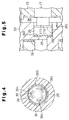
- the compressor of the second embodiment has a valve body 39.
- the valve body 39 includes openings 391, through which gas passes.
- the openings 391 are radially displaced from the discharge port 25. When the valve body 39 contacts the bottom 263 of the recess 26, the openings 391 are shut.
- the embodiment of Fig. 4 has the same advantages as the embodiment of Figs. 1 to 3B.
- the openings 391 reduce the weight of the valve body 39, which improves the response of the valve body 39.
- a projection 171 is integrally formed with the distal end of the eccentric shaft 17.
- the diameter of the projection 171 is smaller than the diameter of the recess 26.
- the end surface 172 of the projection 171 is located in the recess 26.
- the valve body 29 is moved between a closed position, which is illustrated by a solid line, and an open position, which is illustrated by a broken line. At the closed position, the valve body 29 contacts the bottom 263 of the recess 26. At the open position, the valve body 29 contacts the end surface 172 of the projection 171.
- the projection 171 is easily formed on the eccentric shaft 17 and eliminates the necessity for the groove 262 and the snap ring 30
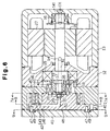
- a fixed scroll 40 is secured to the center housing 12.
- a front cover 41 is secured to the fixed scroll 40.
- a movable scroll 42 is located between the front cover 41 and the fixed scroll 40.
- the movable scroll 42 has a movable volute portion 43.
- a cylindrical portion 421 is formed on the movable scroll 42 at the same side as the volute portion 43.
- the bushing 19 is inserted into the cylindrical portion 421.
- the needle bearing 21 is located between the bushing 19 and the cylindrical portion 421. That is, the movable scroll 42 is supported by the bushing 19 through the cylindrical portion 421 and the needle bearing 21 to rotate relative to the bushing 19.
- the fixed base plate 44, the fixed volute portion 45, the movable base plate 46 and the movable volute portion 43 define pockets S 0 , S 1 , S 2 as shown in Figs. 7A and 8.
- the movable scroll 42 orbits as the eccentric shaft 17 rotates.
- Cylindrical stopper pins 47 are fixed to the front side of the movable base plate 46.
- a pressure receiving plate 48 is located between the front cover 41 and the movable base plate 46.
- holes 49 are formed in the pressure receiving plate 48 and the front cover 41.
- the holes 49 are arranged circumferentially.
- the holes 49 are arranged at equal angular intervals. The ends of the pins 47 are inserted into the corresponding holes 49.
- the orbit radius of the movable scroll 42 is r.
- a discharge port 50 is formed in the movable base plate 46.
- an accommodation recess 26 is formed in the movable base plate 46.
- the recess 26 is located within an area circled by the cylindrical portion 421 adjacent to the recess 26.
- the valve body 29 and the snap ring 30 are located in the area circled by the cylindrical portion 421.
- the recess 26 is connected to the discharge port 50.
- the pockets S2, S1, S0 move toward the inner ends of the volute portions 45, 43 of the scrolls 40, 42.
- the volume of each pocket S2, S1, S0 decreases as it moves. Compressed gas is discharged to the space 35 from the final stage pocket S0 through the discharge port 50.
- a discharge passage 51 is formed in the rotary shaft 14.
- the discharge passage 51 extends from the distal end of the eccentric shaft 17 to a point in the rotary shaft 14. The passage 51 then opens to the surface of the rotary shaft 14. The gas discharged to the space 35 flows to the motor housing 13 through the discharge passage 51.
- the eccentric shaft 17, the bushing 19 and the needle bearing 21 constitute an orbiting mechanism and permit the movable scroll 42 to orbit.
- the orbiting mechanism, the rotary shaft 14 and the volute portion 43 are located on the same side of the movable base plate 46.
- the fixed base plate 44 surrounds the cylindrical portion 421 and the eccentric shaft 17.
- the fixed scroll 40 is arranged at the location corresponding to the vicinity of the front cover 41 of Fig 6 of this invention. Therefore, a space for the discharge chamber is necessarily further forward than the front cover 41 (the left end is forward as viewed in Fig 6).
- the embodiment of Figs. 6 to 9 thus further reduces the axial dimension of the compressor.
- a scroll-type compressor is disclosed.
- the compressor has a fixed scroll (11) and a movable scroll (20).
- Two scrolls (11, 20) respectively have volute portions (32,34) cooperate to form a variable volume gas pocket.
- the movable scroll (20) moves along a predetermined orbital path to vary the volume of the pocket.
- a movable base plate (33) has a discharge port (25) that discharges the gas from the pocket when the volume of the pocket is less than a predetermined volume.
- a valve unit (26, 29, 30) connects and disconnects the discharge port (25) with the gas passage.
- the valve has a movable valve body (39) movable between two positions open and close the discharge port (25).
Landscapes
- Engineering & Computer Science (AREA)
- Mechanical Engineering (AREA)
- General Engineering & Computer Science (AREA)
- Rotary Pumps (AREA)
- Applications Or Details Of Rotary Compressors (AREA)
Abstract
Description
Claims (8)
- A scroll-type compressor having a fixed scroll (11) and a movable scroll (20), the fixed scroll (11) including a fixed base plate (31) and a fixed volute portion (32), which extends from the fixed base plate (31), the movable scroll (20) including a movable base plate (33) and a movable volute portion (34) extending from the movable base plate (33), wherein the two volute portions (32)(34) cooperate to form a variable volume gas pocket, the movable scroll (20) moves along a predetermined orbital path to vary the volume of the pocket and the movable base plate (33) includes a discharge port (25) for discharging the gas from the pocket when the volume of the pocket is less than a predetermined volume, whereby gas is discharged through a predetermined gas passage, the scroll-type compressor being characterized by a valve (26, 29, 30) for selectively connecting and disconnecting the discharge port with the gas passage, the valve including a movable valve body (39) movable between a first position and a second position by a gas flow, wherein the valve body (39) opens the discharge port (25) in the first position and closes the discharge port in the second position.
- The scroll-type compressor as set forth in Claim 1, characterized in that the valve includes an accommodating chamber (26) formed in the movable base plate (33), the valve body (29; 39) accommodated in the accommodating chamber (26), and the compressor further includes a retainer (30; 171) for preventing the valve body (29; 39) from escaping from the chamber (26) and for determining the first position of the valve body (29; 39).
- The scroll-type compressor as set forth in Claim 2, characterized in that the retainer includes a snap ring (30) fitted in the accommodating chamber (26).
- The scroll-type compressor as set forth in Claim 2, characterized in that the retainer includes a projection (131) extending into the chamber (26) from a side opposite to the movable base plate (33).
- The scroll-type compressor as set forth in any one of preceding claims, characterized in that the valve body (39) has a plurality of gas passage holes (391) radially offset from the discharge port.
- The scroll-type compressor as set forth in any one of preceding claims characterized by an orbit mechanism (17, 19, 21) that drives the movable scroll (20) to orbit on a predetermined circular path.
- The scroll-type compressor as set forth in Claim 1, characterized by a drive shaft (14), an eccentric shaft (17) integrally rotatable with the drive shaft (14), a bearing (21) located between the eccentric shaft (17) and the movable scroll (20) and a cylindrical holder (332) projecting from the movable base plate (33), wherein the bearing (21) surrounds a first area, and wherein the valve (26, 29, 30) is located in a second area axially adjacent to the first area in respect with the drive shaft (14) and surrounded by an axial extension of the first area.
- The scroll-type compressor as set forth in any one of the preceding claims, characterized by a motor (27, 28) for driving the drive shaft (14), wherein the gas flowing in the gas passage cools the motor (27, 28).
Applications Claiming Priority (2)
| Application Number | Priority Date | Filing Date | Title |
|---|---|---|---|
| JP25154099 | 1999-09-06 | ||
| JP25154099A JP2001073972A (en) | 1999-09-06 | 1999-09-06 | Discharge structure of scroll compressor |
Publications (2)
| Publication Number | Publication Date |
|---|---|
| EP1081384A2 true EP1081384A2 (en) | 2001-03-07 |
| EP1081384A3 EP1081384A3 (en) | 2002-02-06 |
Family
ID=17224350
Family Applications (1)
| Application Number | Title | Priority Date | Filing Date |
|---|---|---|---|
| EP00119198A Withdrawn EP1081384A3 (en) | 1999-09-06 | 2000-09-05 | Scroll compressor with a discharge valve |
Country Status (2)
| Country | Link |
|---|---|
| EP (1) | EP1081384A3 (en) |
| JP (1) | JP2001073972A (en) |
Cited By (3)
| Publication number | Priority date | Publication date | Assignee | Title |
|---|---|---|---|---|
| WO2020151364A1 (en) * | 2019-01-24 | 2020-07-30 | 艾默生环境优化技术(苏州)有限公司 | Valve assembly and compressor |
| US12259163B2 (en) | 2022-06-01 | 2025-03-25 | Copeland Lp | Climate-control system with thermal storage |
| US12416308B2 (en) | 2022-12-28 | 2025-09-16 | Copeland Lp | Compressor with shutdown assembly |
Families Citing this family (2)
| Publication number | Priority date | Publication date | Assignee | Title |
|---|---|---|---|---|
| CN100378336C (en) * | 2003-06-23 | 2008-04-02 | 乐金电子(天津)电器有限公司 | Anti-overcompression device of scroll compressor |
| CN100387847C (en) * | 2003-12-12 | 2008-05-14 | 乐金电子(天津)电器有限公司 | Gas Backflow Prevention Device for Scroll Compressor |
Family Cites Families (5)
| Publication number | Priority date | Publication date | Assignee | Title |
|---|---|---|---|---|
| JPH02227583A (en) * | 1989-02-28 | 1990-09-10 | Toshiba Corp | Scroll compressor |
| JPH0493781U (en) * | 1990-12-27 | 1992-08-14 | ||
| JP2606454B2 (en) * | 1991-01-08 | 1997-05-07 | 三菱電機株式会社 | Scroll fluid machine |
| JP2541181B2 (en) * | 1991-12-05 | 1996-10-09 | ダイキン工業株式会社 | Valve device |
| JP3139200B2 (en) * | 1993-03-10 | 2001-02-26 | 株式会社豊田自動織機製作所 | Scroll compressor |
-
1999
- 1999-09-06 JP JP25154099A patent/JP2001073972A/en active Pending
-
2000
- 2000-09-05 EP EP00119198A patent/EP1081384A3/en not_active Withdrawn
Cited By (3)
| Publication number | Priority date | Publication date | Assignee | Title |
|---|---|---|---|---|
| WO2020151364A1 (en) * | 2019-01-24 | 2020-07-30 | 艾默生环境优化技术(苏州)有限公司 | Valve assembly and compressor |
| US12259163B2 (en) | 2022-06-01 | 2025-03-25 | Copeland Lp | Climate-control system with thermal storage |
| US12416308B2 (en) | 2022-12-28 | 2025-09-16 | Copeland Lp | Compressor with shutdown assembly |
Also Published As
| Publication number | Publication date |
|---|---|
| EP1081384A3 (en) | 2002-02-06 |
| JP2001073972A (en) | 2001-03-21 |
Similar Documents
| Publication | Publication Date | Title |
|---|---|---|
| US6454551B2 (en) | Seal structure in a scroll type compressor | |
| EP1026402B1 (en) | Scroll-type compressor | |
| US6712589B2 (en) | Scroll compressors | |
| EP1188928B1 (en) | Scroll compressors | |
| CN114729637B (en) | Co-rotating scroll compressor | |
| CN111749886B (en) | Scroll compressor | |
| EP2357364B1 (en) | Scroll compressor | |
| CN112443484B (en) | Electric compressor | |
| US6318982B1 (en) | Scroll-type compressor | |
| EP0043702A2 (en) | Scroll-type fluid displacement apparatus with chamber-pressure equalizing means | |
| CN112443485B (en) | Electric compressor | |
| US12012959B2 (en) | Scroll compressor | |
| US5242282A (en) | Scroll compressor with a driving pin between scrolls and a sliding shaft bearing | |
| CN116498547B (en) | Vortex type electric compressor | |
| KR102566589B1 (en) | Scroll compressor | |
| US10533554B2 (en) | Cylinder-rotation compressor with improved vane and suction passage locations | |
| EP1085211A2 (en) | Discharge valve for a compressor | |
| CN116568929B (en) | Scroll compressor having a rotor with a rotor shaft having a rotor shaft with a | |
| CN111373151B (en) | Scroll compressor having a discharge port for discharging refrigerant from a discharge chamber | |
| US11988206B2 (en) | Scroll compressor with grooves and auxiliary discharge ports | |
| CN116816666B (en) | Scroll compressor | |
| JP7764806B2 (en) | Scroll type electric compressor | |
| JP7823613B2 (en) | Scroll Compressor | |
| CN115126694B (en) | Electric compressor | |
| US20020085937A1 (en) | Scroll type compressor and method of making the same |
Legal Events
| Date | Code | Title | Description |
|---|---|---|---|
| PUAI | Public reference made under article 153(3) epc to a published international application that has entered the european phase |
Free format text: ORIGINAL CODE: 0009012 |
|
| 17P | Request for examination filed |
Effective date: 20000905 |
|
| AK | Designated contracting states |
Kind code of ref document: A2 Designated state(s): DE FR IT Kind code of ref document: A2 Designated state(s): AT BE CH CY DE DK ES FI FR GB GR IE IT LI LU MC NL PT SE |
|
| AX | Request for extension of the european patent |
Free format text: AL;LT;LV;MK;RO;SI |
|
| RAP1 | Party data changed (applicant data changed or rights of an application transferred) |
Owner name: KABUSHIKI KAISHA TOYOTA JIDOSHOKKI |
|
| PUAL | Search report despatched |
Free format text: ORIGINAL CODE: 0009013 |
|
| AK | Designated contracting states |
Kind code of ref document: A3 Designated state(s): AT BE CH CY DE DK ES FI FR GB GR IE IT LI LU MC NL PT SE |
|
| AX | Request for extension of the european patent |
Free format text: AL;LT;LV;MK;RO;SI |
|
| 17Q | First examination report despatched |
Effective date: 20020621 |
|
| AKX | Designation fees paid |
Free format text: DE FR IT |
|
| STAA | Information on the status of an ep patent application or granted ep patent |
Free format text: STATUS: THE APPLICATION IS DEEMED TO BE WITHDRAWN |
|
| 18D | Application deemed to be withdrawn |
Effective date: 20021105 |