EP1081074A2 - Method and device for detecting multiple feed - Google Patents
Method and device for detecting multiple feed Download PDFInfo
- Publication number
- EP1081074A2 EP1081074A2 EP00118178A EP00118178A EP1081074A2 EP 1081074 A2 EP1081074 A2 EP 1081074A2 EP 00118178 A EP00118178 A EP 00118178A EP 00118178 A EP00118178 A EP 00118178A EP 1081074 A2 EP1081074 A2 EP 1081074A2
- Authority
- EP
- European Patent Office
- Prior art keywords
- multiple feed
- light
- light quantity
- value
- sheet
- Prior art date
- Legal status (The legal status is an assumption and is not a legal conclusion. Google has not performed a legal analysis and makes no representation as to the accuracy of the status listed.)
- Granted
Links
Images






Classifications
-
- B—PERFORMING OPERATIONS; TRANSPORTING
- B65—CONVEYING; PACKING; STORING; HANDLING THIN OR FILAMENTARY MATERIAL
- B65H—HANDLING THIN OR FILAMENTARY MATERIAL, e.g. SHEETS, WEBS, CABLES
- B65H7/00—Controlling article feeding, separating, pile-advancing, or associated apparatus, to take account of incorrect feeding, absence of articles, or presence of faulty articles
- B65H7/02—Controlling article feeding, separating, pile-advancing, or associated apparatus, to take account of incorrect feeding, absence of articles, or presence of faulty articles by feelers or detectors
- B65H7/06—Controlling article feeding, separating, pile-advancing, or associated apparatus, to take account of incorrect feeding, absence of articles, or presence of faulty articles by feelers or detectors responsive to presence of faulty articles or incorrect separation or feed
- B65H7/12—Controlling article feeding, separating, pile-advancing, or associated apparatus, to take account of incorrect feeding, absence of articles, or presence of faulty articles by feelers or detectors responsive to presence of faulty articles or incorrect separation or feed responsive to double feed or separation
- B65H7/125—Controlling article feeding, separating, pile-advancing, or associated apparatus, to take account of incorrect feeding, absence of articles, or presence of faulty articles by feelers or detectors responsive to presence of faulty articles or incorrect separation or feed responsive to double feed or separation sensing the double feed or separation without contacting the articles
-
- B—PERFORMING OPERATIONS; TRANSPORTING
- B65—CONVEYING; PACKING; STORING; HANDLING THIN OR FILAMENTARY MATERIAL
- B65H—HANDLING THIN OR FILAMENTARY MATERIAL, e.g. SHEETS, WEBS, CABLES
- B65H2511/00—Dimensions; Position; Numbers; Identification; Occurrences
- B65H2511/50—Occurence
- B65H2511/52—Defective operating conditions
- B65H2511/524—Multiple articles, e.g. double feed
-
- B—PERFORMING OPERATIONS; TRANSPORTING
- B65—CONVEYING; PACKING; STORING; HANDLING THIN OR FILAMENTARY MATERIAL
- B65H—HANDLING THIN OR FILAMENTARY MATERIAL, e.g. SHEETS, WEBS, CABLES
- B65H2553/00—Sensing or detecting means
- B65H2553/40—Sensing or detecting means using optical, e.g. photographic, elements
- B65H2553/41—Photoelectric detectors
- B65H2553/412—Photoelectric detectors in barrier arrangements, i.e. emitter facing a receptor element
-
- B—PERFORMING OPERATIONS; TRANSPORTING
- B65—CONVEYING; PACKING; STORING; HANDLING THIN OR FILAMENTARY MATERIAL
- B65H—HANDLING THIN OR FILAMENTARY MATERIAL, e.g. SHEETS, WEBS, CABLES
- B65H2557/00—Means for control not provided for in groups B65H2551/00 - B65H2555/00
- B65H2557/20—Calculating means; Controlling methods
- B65H2557/23—Recording or storing data
Definitions
- This invention relates to a multiple feed detection device for detecting a feed of two or more overlapped sheets (multiple feed) when sheets are carried along a carriage path, and more particularly to a method and a device for detecting a multiple feed suitable for the multiple feed detection of prints.
- a collator shown in Figs.8, 9A, and 9B is known as an apparatus for collating a plurality of different prints by overlapping them one by one from the first page to make bundles of a desired number of copies of the prints.
- Fig.8 shows an external view illustrating an entire collator
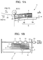
- Fig.9A shows a partially enlarged sectional view of each bin taken from Fig.8
- Fig.9B shows a view illustrating each bin as viewed in the direction indicated by the arrow A in Fig.9A.
- arrows indicate the flow of sheets for each bin.
- a collator 1 comprises a plurality of bins (10 bins in an example of Fig. 8) 2 in which different prints (sheets) are to be set.
- the bins 2 (2 1 to 2 10 ) are arranged in parallel in spaced apart relation provided vertically with respect to a body 3 and disposed to be protruded with a predetermined distance from the front surface of the body 3.
- a sheet discharge tray 5 for collating and discharging prints 4 which are fed from each bin 2 one by one is disposed to be protruded with a predetermined distance from the front surface of the body 3 at the lowest part of the body 3.
- a carriage mechanism is provided inside the body 3, e.g., carrier rollers or carrier belts for carrying the prints 4 fed from each bin 2 onto the sheet discharge tray 5.
- Each bin 2 comprises a sheet feed base 6 on which the prints 4 are set.
- the sheet feed base 6 includes a fixed part 6a and a movable part 6b which is vertically movable by a shift mechanism driven by a motor (not shown).
- a sheet-detecting sensor 7 for detecting any presence of the prints 4 to be set e.g., a reflector-type sensor, is disposed in the movable part 6b.
- a sheet feed fence 8 movable in accordance with the size of the prints 4 to be set is disposed on the sheet feed base 6.
- the sheet feed fence 8 in Fig.9B is provided to be fixed at the right side and movable in accordance with the size (width) of the prints at the left side.
- a sheet feed roller 9 and a handling plate 10 for carrying the prints 4 set on the sheet feed base 6 one by one from the top to the body 3 are provided to be opposed to one another in each bin 2.
- Auxiliary rollers 11 for keeping the prints 4, e.g., from being curled, are disposed at both sides of the sheet feed roller 9.
- the rotation axis 12 of the sheet feed roller 9 and the auxiliary rollers 11 is connected through a sheet feed clutch 13 to a main motor (drive motor 26).
- the sheet feed roller 9 and the auxiliary rollers 11 rotate by means of drive of the main motor in a clockwise direction in Fig.9A.
- Multiple feed sensors 15 as a sheet detector for detecting a multiple feed of the prints 4 to be fed are disposed around a carriage path between the sheet feed roller 9 of each bin 2 and the carriage mechanism of the body 3.
- the multiple feed sensors 15 are constituted by a transmission-type of optical sensors comprising a light emitting sensor 15a and a light receiving sensor 15b.
- the light emitting sensor 15a is, for example, constituted by a light emitting diode, a laser diode, or a lamp.
- the light emitting sensor 15a is disposed at a predetermined distance apart from the carriage path 16 along which the prints 4 are fed.
- the light receiving sensor 15b is, for example, constituted by a photodiode.
- the light receiving sensor 15b is disposed to be opposed to the light emitting sensor 15a at a predetermined distance apart from the carriage path 16, e.g., in an equally spaced apart relation between the light emitting sensor 15a and the carriage path 16 such that the carriage path 16 on which the prints 4 are fed is sandwiched between the sensors.
- the light emitted from the light emitting sensor 15a is directly received by the light receiving sensor 15b, whereas if the prints 4 are carried, the light transmitted through the prints 4 is received by the light receiving sensor 15b.
- the collator 1 when the prints 4 having pages 1 to 10 are respectively set to the bins 2 1 to 2 10 in order, e.g., the prints 4 of page 1 to 2 1 , the prints 4 of page 2 to 2 2 , the prints 4 are fed one by one subsequently from the bin 2 1 positioned in the highest part, and discharged onto the sheet discharge tray 5. This allows the collated prints 4 to be discharged as a copy of the pages 1 to 10 onto the sheet discharge tray 5.
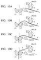
- Each of the prints 4 set in each of the bins 2 is fed inside the body 3 through the following states: that is, the state where it is approaching carrier rollers 17 of the carriage mechanism of the body 3 as shown in Fig.10A, the state where it has reached the carrier rollers 17 and a loose is then produced as shown in Fig.10B, the state where it is pressed by the sheet feed roller 9 and the carrier rollers 17 so that the position of it passing between the multiple feed sensors 15 is fixed as shown in Fig.10C, and the state where the end thereof leaves the sheet feed roller 9 and thereby rises upward.
- Fig. 11 illustrates an example of the light transmission quantity of the prints at the time of the sheet feed. This shows that when the slack or springing of the prints 4 develops as shown in Figs.10B and 10D, the light transmission quantity of the prints 4 drastically changes as shown in respective regions (i) and (ii) in Fig.11 so that it cannot be stable.
- the conventional method as stated above may have caused a problem in that if the light transmission quantity of the prints 4, when the slack or springing of the prints 4 develops as shown in Figs.10B and 10D, is measured as the maximum value, the measured value is not less than a reference value even when a multiple feed really occurs, thereby causing misdetection.
- Fig.16 shows a frequency distribution representative of the light transmission quantity (analog-to-digital (A/D) converted value) when the prints pass between the multiple feed sensors.
- Fig.16 shows that a histogram representative of the frequency at each of the A/D converted values indicates the clear discrimination between the "underlying portion" enclosed with broken lines A and the "printed portion” enclosed with broken lines B .
- a multiple feed detection device comprising: a sheet detector having a light emitting sensor and a light receiving sensor arranged in vicinity of a carriage path to detect quantity of light that has transmitted through a sheet; a memory which stores a predetermined sampling number of electric signals indicative of light quantity outputted from the sheet detector; and a processor which creates a histogram of the light quantity stored in the memory, obtains the light quantity corresponding to a maximum frequency for an underlying portion of sheets based on the created histogram, and detects a multiple feed of the sheets based on a variation in the light quantity of the maximum frequency.
- the processor scans frequencies from the light quantity indicative of a low level of darkness toward that indicative of a high level thereof and then detects a peak of the frequencies that satisfies a predetermined condition as the light quantity corresponding to the maximum frequency.
- the processor calculates a total sum of the frequencies corresponding to a predetermined number of the light quantities adjacent to a light quantity of interest, and detects one of the light quantities adjacent to the light quantity of interest as the light quantity corresponding to the maximum frequency if the total sum of the frequencies reaches a value which is a certain ratio of the predetermined sample value.
- the processor at the time of feeding of a first sheet, regards a value that is a certain ratio of the light quantity corresponding to the maximum frequency as a reference value for detecting the multiple feed of the sheets, and at the time of feeding of a second or successive sheet, regards the light quantity corresponding to the maximum frequency as a comparison value and compares the comparison value with the reference value thereby to detect the multiple feed of the sheets.
- a multiple feed detection method comprising the steps of: arranging sheet detector having a light emitting sensor and a light receiving sensor in vicinity of a carriage path to detect quantity of light that has transmitted through a sheet; storing a predetermined sampling number of electric signals indicative of light quantity outputted from the sheet detector in a memory; creating a histogram of the light quantity stored in the memory; detecting the light quantity corresponding to a maximum frequency for an underlying portion of sheets based on the created histogram; and detecting a multiple feed of the sheets based on a variation in the light quantity of the maximum frequency.
- frequencies are scanned from the light quantity indicative of a low level of darkness toward that indicative of a high level thereof, and then a peak of the frequencies that satisfies a predetermined condition is detected as the light quantity corresponding to the maximum frequency.
- a total sum of the frequencies corresponding to a predetermined number of the light quantities adjacent to a light quantity of interest is calculated, and if the total sum of the frequencies reaches a value which is a certain ratio of the predetermined sample value, then one of the light quantities adjacent to the light quantity of interest is detected as the light quantity corresponding to the maximum frequency.
- a value that is a certain ratio of the light quantity corresponding to the maximum frequency is regarded as a reference value for detecting the multiple feed of the sheets
- the light quantity corresponding to the maximum frequency is regarded as a comparison value and then the comparison value is compared with the reference value thereby to detect the multiple feed of the sheets.
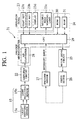
- Fig.1 shows a block diagram illustrating the case where a multiple feed detection device of the invention is applied to the collator shown in Figs.8 to 10.
- a multiple feed detection device 21 comprises a multiple feed sensor 15, an amplifier circuit 22, an operation panel 23, a microcomputer 24, a motor drive circuit 25, a drive motor 26, and encoder sensor 27.
- the amplifier circuit 22 amplifies an electrical signal indicative of the light transmission quantity received from a light receiving sensor 15b of the multiple feed sensor 15 by a predetermined amplification factor and then supplies the signal to the microcomputer 24.
- the operation panel 23 may include operation keys manipulated by a user, e.g., a start key 23a for designating the start of the collating operation and a stop key 23b for designating the stop of the collating operation.
- a multiple feed warning lamp 23c which is lit when any multiple feed (that is, two or more sheets of the prints 4 are fed in the overlapped state) occurs, is provided on the operation panel 23.
- a display 23d e.g., a liquid crystal display, for providing various displays such as a display of a message of the multiple feed warning is provided on the operation panel 23.
- the microcomputer 24 as a processor is constituted of one-chip microcomputer comprising an A/D converter 28, CPU 29, and ROM 30 and RAM 31.
- the A/D converter 28 converts the received signal from the amplifier circuit 22 to a digital signal corresponding to the analog signal, and supplies it to the CPU 29 as the light transmission quantity.
- the CPU 29 includes a microprocessor and so on, and conducts a carriage control of the prints 4, setting of a sampling range, multiple feed detection of the prints 4 according to the flow diagrams shown in Figs.2 and 3 as explained later, etc. based on the information from the operation panel 23, the signal from the amplifier circuit 22, and the signal from the encoder sensor 27.
- the CPU 29 samples the digital signal received from the A/D converter 28 at an input timing of the interrupt signal from the encoder sensor 27 within a previously set sampling range.
- the sampling range is set as the count number of pulses of the encoder sensor 27 from a reference point in time of detection of the front end of the prints 4 by the multiple feed sensor 15.
- the CPU 29 issues commands for controlling the drive and stop of the drive motor 26 to the motor drive circuit 25 based on the operation signals from the start key 23a and the stop key 23b on the operation panel 23.
- the CPU 29 has a sheet feed counter therein, and increments by one the counts in response to an interrupt signal received from the encoder sensor 27.
- the ROM 30 stores processing programs necessary for conducting a sequence of processes containing the processes shown in Figs.2 and 3 by the CPU 29, data of the sampling range in accordance with the size of the prints 4, etc.
- the RAM 31 stores the sampling data for the first sheet of the prints 4 within the sampling range set by the CPU 29, and successively stores, by updating, the sampling data for the second or successive sheet of the prints 4 within the sampling range set by the CPU 29.
- the RAM 31 stores the counts by the sheet feed counter in the CPU 29.
- the motor drive circuit 25 drives or stops the rotation of the drive motor 26 based on the commands issued by the CPU 29.
- the encoder sensor 27 produces a one-shot pulse signal when the drive motor 26 rotates until a predetermined length of the prints 4 is fed. This one-shot pulse signal is supplied as an interrupt signal to the CPU 29.
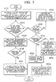
- sampling of the light transmission quantity of the prints 4 is started. That is, the pulse signals from the encoder sensor 27 are counted from a reference point in time when the multiple feed sensor 15 detects the front edge of the first sheet, and if the count reaches the value of the sampling start position, the light transmission quantity which is converted by the A/D converter 28 via the amplifier circuit 22 from the multiple feed sensor 15 is supplied to the CPU 29. The light transmission quantity is then stored in the RAM 31 (ST2).
- the accuracy of the multiple feed detection improves as the total sampling number in such a sampling increases.
- limitations may be imposed in terms of the capacity of the RAM 31 or the arithmetic processing speed of the CPU 29. Without any problem on the capacity of the RAM 31 or the arithmetic processing speed of the CPU 29, shorter distances between samplings within the same sampling region allows the total sampling number to be increased. In contrast with this, with the small capacity of the RAM 31 and the low arithmetic processing speed of the CPU 29, the sampling distance may be wider.
- sampling of the light transmission quantity of the sheet is started. That is, the pulse signals of the encoder sensor 27 are counted from a reference point in time when the multiple feed sensor 15 detects the front edge of the second or successive sheet, and if the count reaches the value of the sampling start position, the light transmission quantity which is converted by the A/D converter 28 via the amplifier circuit 22 from the multiple feed sensor 15 is supplied to the CPU 29. The light transmission quantity is then stored in the RAM 31 (ST12).
- the light transmission quantity when no sheet is fed may be selected, otherwise a value that is smaller by a predetermined value than the light transmission quantity when no sheet is fed may be selected with considering reduction in time of arithmetic processing.
- the value of ⁇ is a predetermined integer value ("4" for example). The smaller this value becomes, the shorter the arithmetic processing time for one processing becomes.
- the detection of multiple feed cannot be conducted, which is notified to the user (ST26).
- the value of " ⁇ " is set to a predetermined value which is a certain ratio (e.g., 10%) of the light transmission quantity at the time of a non-sheet feed.
- a multiple feed detection signal is produced from the CPU 29 (ST27) to start the operations for coping with the multiple feed (ST28).
- the sheet feeds from all the bins 2 are stopped, and the multiple feed warning lamp 23c on the operation panel 23 is lit to notify the occurrence of the multiple feed to the user. At this time, it may be also notified to the user which bin is related with the multiple feed.
- the maximum frequency among the summed frequencies is then regarded as the light transmission quantity of the underlying portion of the prints 4.
- the carriage is a carriage for the first sheet of the sheets 4 (ST30-YES)
- reference values for detecting a multiple feed are obtained from the obtained light transmission quantity (ST31).
- Each of the reference values is a value which is a certain ratio of the light transmission quantity which corresponds to the maximum frequency among the summed frequencies.
- the reference values may be values which are 75% and 150% of the light transmission quantity corresponding to the maximum frequency among the summed frequencies.
- the carriage is a carriage of the second or successive sheet of the prints (ST30-NO)
- the light transmission quantity which corresponds to the maximum frequency among the summed frequencies is regarded as a comparison value (a value to be compared with the reference values) (ST32), and then the comparison value is compared with the reference values to detect a multiple feed.
- the multiple feed detection signal is produced from the CPU 29 (ST16) and the operation for the multiple feed is started (ST17). For example, after collated prints including the multiply fed prints are discharged onto the sheet discharge tray 5, the sheet feeds from all the bins 2 are stopped, and the multiple feed warning lamp 23c on the operation panel 23 is lit to notify the occurrence of the multiple feed to the user. At this time, it may be also notified to the user which bin is related with the multiple feed. If no multiple feed is detected (ST15-NO) and the prints 4 to be fed remain (ST18-YES), the process returns to the step ST11.
- Fig.4 shows an example of a histogram in a range of multiple feed detection sampling where no multiple feed has occurred
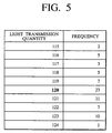
- Fig.5 shows a view presenting the sum of frequencies for calculating a comparison value for the case in Fig.4
- Fig.6 shows an example of a histogram in a range of the multiple feed detection sampling where a multiple feed has occurred
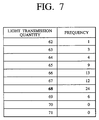
- Fig.7 shows a view presenting the sum of frequencies for calculating a comparison value for the case in Fig.6.
- the comparison value "68" is then compared with the reference values of "90" and "180" which are calculated at the time of the feed of the first sheet of the prints 4. In this case, it is decided that the multiple feed occurs since the comparison value "68" is smaller than the reference value "90".
- a histogram for obtaining the frequency of the light transmission quantity of the prints is created, and based on the frequencies distribution, a peak of the frequencies corresponding to the underlying portion of the prints is detected, and then the variation in the light transmission quantity corresponding to the maximum frequency is used for the multiple feed detection among the detected frequencies of the peak. For this reason, the rate of successful multiple feed detection increases as compared with the conventional methods.
- the multiple feed sensor 15 is a pair of light emitting and receiving sensors of light transmission type arranged to be opposed to each other and to sandwich the prints 4 carried along the carriage path 16, the invention is not limited thereto and a pair of light emitting and receiving sensors of reflection type arranged in one side of the carriage can be also adapted.
- the value of electrical signals analog-to-digital converted is not the light transmission quantity but the light reflection quantity.
- sheets subjected to the multiple feed detection are not, of course, limited to the prints but include non-printed papers for purpose of inserting papers.
- a histogram for obtaining the frequency of the light transmission quantity of the prints is created, and based on the frequencies distribution, a peak of the frequencies corresponding to the underlying portion of the prints is detected, and then the variation in the light transmission quantity corresponding to the maximum frequency is used for the multiple feed detection among the detected frequencies of the peak. Therefore, the rate of successful multiple feed detection increases as compared with the conventional methods.
Landscapes
- Controlling Sheets Or Webs (AREA)
Abstract
Description
Claims (8)
- A multiple feed detection device comprising:a sheet detector (15) having a light emitting sensor (15a) and a light receiving sensor (15b) arranged in vicinity of a carriage path (16) to detect quantity of light that has transmitted through a sheet (4);a memory (31) which stores a predetermined sampling number of electric signals indicative of light quantity outputted from the sheet detector (15); anda processor (29) which creates a histogram of the light quantity stored in said memory (31), obtains the light quantity corresponding to a maximum frequency for an underlying portion of sheets based on the created histogram, and detects a multiple feed of said sheets based on a variation in the light quantity of the maximum frequency.
- The multiple feed detection device according to claim 1, wherein said processor (29) scans frequencies from the light quantity indicative of a low level of darkness toward that indicative of a high level thereof and then detects a peak of the frequencies that satisfies a predetermined condition as the light quantity corresponding to the maximum frequency.
- The multiple feed detection device according to claim 2, wherein said processor (29) calculates a total sum of the frequencies corresponding to a predetermined number of the light quantities adjacent to a light quantity of interest, and detects one of the light quantities adjacent to the light quantity of interest as the light quantity corresponding to the maximum frequency if the total sum of the frequencies reaches a value which is a certain ratio of the predetermined sample value.
- The multiple feed detection device according to claim 3, wherein said processor (29), at the time of feeding of a first sheet, regards a value that is a certain ratio of the light quantity corresponding to the maximum frequency as a reference value for detecting the multiple feed of said sheets, and at the time of feeding of a second or successive sheet, regards the light quantity corresponding to the maximum frequency as a comparison value and compares the comparison value with the reference value thereby to detect the multiple feed of said sheets.
- A multiple feed detection method comprising the steps of:arranging a sheet detector (15) having a light emitting sensor (15a) and a light receiving sensor (15b) in vicinity of a carriage path (16) to detect quantity of light that has transmitted through a sheet;storing a predetermined sampling number of electric signals indicative of light quantity outputted from the sheet detector (15) in a memory (31);creating a histogram of the light quantity stored in said memory (31);detecting the light quantity corresponding to a maximum frequency for an underlying portion of sheets based on the created histogram; anddetecting a multiple feed of said sheets based on a variation in the light quantity of the maximum frequency.
- The multiple feed detection method according to claim 5, wherein frequencies are scanned from the light quantity indicative of a low level of darkness toward that indicative of a high level thereof, and then a peak of the frequencies that satisfies a predetermined condition is detected as the light quantity corresponding to the maximum frequency.
- The multiple feed detection method according to claim 6, wherein a total sum of the frequencies corresponding to a predetermined number of the light quantities adjacent to a light quantity of interest is calculated, and if the total sum of the frequencies reaches a value which is a certain ratio of the predetermined sample value, then one of the light quantities adjacent to the light quantity of interest is detected as the light quantity corresponding to the maximum frequency.
- The multiple feed detection method according to claim 7, wherein, at the time of feeding of a first sheet, a value that is a certain ratio of the light quantity corresponding to the maximum frequency is regarded as a reference value for detecting the multiple feed of said sheets, and at the time of feeding of a second or successive sheet, the light quantity corresponding to the maximum frequency is regarded as a comparison value and then the comparison value is compared with the reference value thereby to detect the multiple feed of said sheets.
Applications Claiming Priority (2)
| Application Number | Priority Date | Filing Date | Title |
|---|---|---|---|
| JP24589899 | 1999-08-31 | ||
| JP24589899A JP3431866B2 (en) | 1999-08-31 | 1999-08-31 | Double feed detection device and double feed detection method |
Publications (3)
| Publication Number | Publication Date |
|---|---|
| EP1081074A2 true EP1081074A2 (en) | 2001-03-07 |
| EP1081074A3 EP1081074A3 (en) | 2001-10-31 |
| EP1081074B1 EP1081074B1 (en) | 2004-04-07 |
Family
ID=17140471
Family Applications (1)
| Application Number | Title | Priority Date | Filing Date |
|---|---|---|---|
| EP00118178A Expired - Lifetime EP1081074B1 (en) | 1999-08-31 | 2000-08-30 | Method and device for detecting multiple feed |
Country Status (5)
| Country | Link |
|---|---|
| US (1) | US6473674B1 (en) |
| EP (1) | EP1081074B1 (en) |
| JP (1) | JP3431866B2 (en) |
| CN (1) | CN1128089C (en) |
| DE (1) | DE60009617T2 (en) |
Cited By (2)
| Publication number | Priority date | Publication date | Assignee | Title |
|---|---|---|---|---|
| US6473674B1 (en) * | 1999-08-31 | 2002-10-29 | Riso Kagaku Corporation | Method and device for detecting multiple feed |
| EP1679273A1 (en) * | 2005-01-07 | 2006-07-12 | Ricoh Company, Ltd. | Medium discrimination device, image forming apparatus, and program having simplified mechanism |
Families Citing this family (8)
| Publication number | Priority date | Publication date | Assignee | Title |
|---|---|---|---|---|
| US20080036139A1 (en) * | 2006-08-14 | 2008-02-14 | Gregory Reyner | Non-contact sensing system |
| JP2009035399A (en) * | 2007-08-02 | 2009-02-19 | Duplo Corp | Double feed detector |
| US8761487B2 (en) * | 2011-12-15 | 2014-06-24 | Ncr Corporation | Methods of operating an image-based check processing system to detect a double feed condition of checks and an apparatus therefor |
| US8625877B2 (en) * | 2011-12-15 | 2014-01-07 | Ncr Corporation | Methods of operating an image-based check processing system to detect a double feed condition of carrier envelopes and an apparatus therefor |
| JP6158611B2 (en) * | 2013-06-26 | 2017-07-05 | 理想科学工業株式会社 | Transport device |
| JP6200277B2 (en) * | 2013-10-28 | 2017-09-20 | 理想科学工業株式会社 | Image forming apparatus and image forming system |
| US10373007B2 (en) * | 2017-03-29 | 2019-08-06 | Ncr Corporation | Double feed exceptions identifying system |
| JP7087287B2 (en) * | 2017-06-29 | 2022-06-21 | セイコーエプソン株式会社 | Image reader |
Family Cites Families (13)
| Publication number | Priority date | Publication date | Assignee | Title |
|---|---|---|---|---|
| US3882308A (en) * | 1970-04-06 | 1975-05-06 | Xerox Corp | Detection system for superposed sheets |
| US4395111A (en) * | 1980-08-28 | 1983-07-26 | Canon Kabushiki Kaisha | Sheet conveying device |
| US4714946A (en) * | 1985-11-27 | 1987-12-22 | International Business Machines Corporation | Continuous form feeder for a reproducing machine and process |
| US4962393A (en) * | 1988-05-12 | 1990-10-09 | Sci Systems, Inc. | Printing apparatus |
| US4922110A (en) * | 1988-04-15 | 1990-05-01 | Brandt, Inc. | Document counter and endorser |
| GB8921142D0 (en) | 1989-09-19 | 1989-11-08 | Watkiss Automation Ltd | Sheet feeding mechanisms and apparatus |
| US5226640A (en) * | 1991-05-31 | 1993-07-13 | Puzey Jon C | Sheet feeding apparatus with pressure sensing vacuum assembly |
| US5318286A (en) * | 1992-02-13 | 1994-06-07 | Mita Industrial Co., Ltd. | Parallel transport apparatus |
| US5831748A (en) | 1994-12-19 | 1998-11-03 | Minolta Co., Ltd. | Image processor |
| US5861646A (en) * | 1997-03-24 | 1999-01-19 | Ncr Corporation | Method of processing documents moving along a transport path of a document processing system and an apparatus therefor |
| JP3479433B2 (en) * | 1997-07-02 | 2003-12-15 | 理想科学工業株式会社 | Overfeed detector |
| JP3393175B2 (en) * | 1997-07-02 | 2003-04-07 | 理想科学工業株式会社 | Paper feeder for printing press |
| JP3431866B2 (en) * | 1999-08-31 | 2003-07-28 | 理想科学工業株式会社 | Double feed detection device and double feed detection method |
-
1999
- 1999-08-31 JP JP24589899A patent/JP3431866B2/en not_active Expired - Lifetime
-
2000
- 2000-08-29 US US09/649,578 patent/US6473674B1/en not_active Expired - Lifetime
- 2000-08-30 EP EP00118178A patent/EP1081074B1/en not_active Expired - Lifetime
- 2000-08-30 DE DE60009617T patent/DE60009617T2/en not_active Expired - Fee Related
- 2000-08-31 CN CN00124319.5A patent/CN1128089C/en not_active Expired - Lifetime
Cited By (3)
| Publication number | Priority date | Publication date | Assignee | Title |
|---|---|---|---|---|
| US6473674B1 (en) * | 1999-08-31 | 2002-10-29 | Riso Kagaku Corporation | Method and device for detecting multiple feed |
| EP1679273A1 (en) * | 2005-01-07 | 2006-07-12 | Ricoh Company, Ltd. | Medium discrimination device, image forming apparatus, and program having simplified mechanism |
| US7443490B2 (en) | 2005-01-07 | 2008-10-28 | Ricoh Co., Ltd. | Medium discrimination device, image forming apparatus, and program having simplified mechanism |
Also Published As
| Publication number | Publication date |
|---|---|
| DE60009617D1 (en) | 2004-05-13 |
| DE60009617T2 (en) | 2005-03-24 |
| CN1128089C (en) | 2003-11-19 |
| EP1081074A3 (en) | 2001-10-31 |
| EP1081074B1 (en) | 2004-04-07 |
| JP2001063871A (en) | 2001-03-13 |
| US6473674B1 (en) | 2002-10-29 |
| JP3431866B2 (en) | 2003-07-28 |
| CN1286204A (en) | 2001-03-07 |
Similar Documents
| Publication | Publication Date | Title |
|---|---|---|
| EP1081073B1 (en) | Method and device for detecting multiple feed | |
| US5961115A (en) | Method and system of sensing an output level of an output stack of print media in an image forming apparatus | |
| EP0143188B1 (en) | Method of and device for detecting displacement of paper sheets | |
| JP3393175B2 (en) | Paper feeder for printing press | |
| US5110106A (en) | Sheet size detector for sheet container | |
| US6378683B2 (en) | Method and apparatus for discriminating and counting documents | |
| US7817842B2 (en) | Method and apparatus for discriminating and counting documents | |
| EP1081074B1 (en) | Method and device for detecting multiple feed | |
| JPS63228286A (en) | Monitoring method and classification device using the method | |
| GB2088832A (en) | Bank note receiving apparatus | |
| US5912448A (en) | Method and apparatus for detecting paper skew in image and document scanning devices | |
| JP2739471B2 (en) | Method and apparatus for controlling sheet feeding and counting | |
| US5204726A (en) | Copying paper feed sensing device for a copying apparatus | |
| GB2122584A (en) | Printer with automatic stacker | |
| KR950008426B1 (en) | Fax Source Control Method | |
| JPH06336352A (en) | Residual sheet of paper detecting device | |
| US5560725A (en) | Device for feeding a continuous rolled strip of printing substrate to a laser printer not otherwise configured therefor | |
| JP2736808B2 (en) | Paper sheet identification device | |
| JPH0543091A (en) | Device for detecting original sent on piles in image reader | |
| EP0714846B1 (en) | Method for determining the displacement of an object | |
| JP3704415B2 (en) | Foreign matter detection device for paper sheets | |
| JPH06111096A (en) | Paper discriminating device | |
| EP0488661A2 (en) | A paper feeder and an image forming apparatus provided with the same | |
| JPH07272043A (en) | Paper type classification device | |
| JPH0577968A (en) | Method and device for controlling optical sensor |
Legal Events
| Date | Code | Title | Description |
|---|---|---|---|
| PUAI | Public reference made under article 153(3) epc to a published international application that has entered the european phase |
Free format text: ORIGINAL CODE: 0009012 |
|
| 17P | Request for examination filed |
Effective date: 20000830 |
|
| AK | Designated contracting states |
Kind code of ref document: A2 Designated state(s): AT BE CH CY DE DK ES FI FR GB GR IE IT LI LU MC NL PT SE Kind code of ref document: A2 Designated state(s): DE FR GB |
|
| AX | Request for extension of the european patent |
Free format text: AL;LT;LV;MK;RO;SI |
|
| PUAL | Search report despatched |
Free format text: ORIGINAL CODE: 0009013 |
|
| AK | Designated contracting states |
Kind code of ref document: A3 Designated state(s): AT BE CH CY DE DK ES FI FR GB GR IE IT LI LU MC NL PT SE |
|
| AX | Request for extension of the european patent |
Free format text: AL;LT;LV;MK;RO;SI |
|
| AKX | Designation fees paid |
Free format text: DE FR GB |
|
| GRAP | Despatch of communication of intention to grant a patent |
Free format text: ORIGINAL CODE: EPIDOSNIGR1 |
|
| GRAS | Grant fee paid |
Free format text: ORIGINAL CODE: EPIDOSNIGR3 |
|
| GRAA | (expected) grant |
Free format text: ORIGINAL CODE: 0009210 |
|
| RIN1 | Information on inventor provided before grant (corrected) |
Inventor name: OKADA, SHINYA,RISO KAGAKU CORPORATION |
|
| AK | Designated contracting states |
Kind code of ref document: B1 Designated state(s): DE FR GB |
|
| REG | Reference to a national code |
Ref country code: GB Ref legal event code: FG4D |
|
| REF | Corresponds to: |
Ref document number: 60009617 Country of ref document: DE Date of ref document: 20040513 Kind code of ref document: P |
|
| ET | Fr: translation filed | ||
| PLBE | No opposition filed within time limit |
Free format text: ORIGINAL CODE: 0009261 |
|
| STAA | Information on the status of an ep patent application or granted ep patent |
Free format text: STATUS: NO OPPOSITION FILED WITHIN TIME LIMIT |
|
| 26N | No opposition filed |
Effective date: 20050110 |
|
| PGFP | Annual fee paid to national office [announced via postgrant information from national office to epo] |
Ref country code: DE Payment date: 20080912 Year of fee payment: 9 |
|
| PGFP | Annual fee paid to national office [announced via postgrant information from national office to epo] |
Ref country code: FR Payment date: 20080818 Year of fee payment: 9 |
|
| PGFP | Annual fee paid to national office [announced via postgrant information from national office to epo] |
Ref country code: GB Payment date: 20080903 Year of fee payment: 9 |
|
| GBPC | Gb: european patent ceased through non-payment of renewal fee |
Effective date: 20090830 |
|
| REG | Reference to a national code |
Ref country code: FR Ref legal event code: ST Effective date: 20100430 |
|
| PG25 | Lapsed in a contracting state [announced via postgrant information from national office to epo] |
Ref country code: FR Free format text: LAPSE BECAUSE OF NON-PAYMENT OF DUE FEES Effective date: 20090831 Ref country code: DE Free format text: LAPSE BECAUSE OF NON-PAYMENT OF DUE FEES Effective date: 20100302 |
|
| PG25 | Lapsed in a contracting state [announced via postgrant information from national office to epo] |
Ref country code: GB Free format text: LAPSE BECAUSE OF NON-PAYMENT OF DUE FEES Effective date: 20090830 |