EP1081028A2 - A computer-implemented method and apparatus for integrating vehicle manufacturing operations - Google Patents
A computer-implemented method and apparatus for integrating vehicle manufacturing operations Download PDFInfo
- Publication number
- EP1081028A2 EP1081028A2 EP00117763A EP00117763A EP1081028A2 EP 1081028 A2 EP1081028 A2 EP 1081028A2 EP 00117763 A EP00117763 A EP 00117763A EP 00117763 A EP00117763 A EP 00117763A EP 1081028 A2 EP1081028 A2 EP 1081028A2
- Authority
- EP
- European Patent Office
- Prior art keywords
- data
- data structure
- manufacturing
- module
- vehicles
- Prior art date
- Legal status (The legal status is an assumption and is not a legal conclusion. Google has not performed a legal analysis and makes no representation as to the accuracy of the status listed.)
- Withdrawn
Links
Images




Classifications
-
- B—PERFORMING OPERATIONS; TRANSPORTING
- B62—LAND VEHICLES FOR TRAVELLING OTHERWISE THAN ON RAILS
- B62D—MOTOR VEHICLES; TRAILERS
- B62D65/00—Designing, manufacturing, e.g. assembling, facilitating disassembly, or structurally modifying motor vehicles or trailers, not otherwise provided for
- B62D65/02—Joining sub-units or components to, or positioning sub-units or components with respect to, body shell or other sub-units or components
-
- B—PERFORMING OPERATIONS; TRANSPORTING
- B62—LAND VEHICLES FOR TRAVELLING OTHERWISE THAN ON RAILS
- B62D—MOTOR VEHICLES; TRAILERS
- B62D65/00—Designing, manufacturing, e.g. assembling, facilitating disassembly, or structurally modifying motor vehicles or trailers, not otherwise provided for
Definitions
- the present invention relates generally to computer-implemented vehicle manufacturing systems, and more particularly, to computer-implemented systems for integrating vehicle manufacturing operations.
- Design decisions are also affected by what vehicle plant personnel uncover during vehicle assembly. The feedback by plant personnel needs to be more effectively and efficiently communicated to the proper design personnel.
- a computer-implemented method and apparatus for designing and manufacturing vehicles in a distributed design environment and manufacturing plant environment.
- a database preferably a relational database, is provided for storing vehicle design data (e.g., tool, part, weld, and torque data) related to the vehicles.
- vehicle design data e.g., tool, part, weld, and torque data
- a process sheet data structure is used to interrelate the tool, part, weld, and torque data in order to generate process sheet data that depicts the assembly process of the vehicles.
- the assembly process contains the steps to assemble the vehicles.
- a manufacturing plant data structure is linked to the process sheet data structure for containing station data and production data for assembling the vehicles in the manufacturing plants.
- the manufacturing plant data structure associates the station data with the process sheet data in order to indicate the assembly steps for a station contained within the manufacturing data structure.
- a financial data structure is used to link to the manufacturing plant data structure in order to contain financial data associated with the assembly of the vehicle and the manufacturing plant.
- Figure 1 depicts the integrated automated design and manufacturing planning system that integrates top level vehicle engineering design data with manufacturing plant data and with financial information.
- This comprehensive integrated data set 24 from the different aspects of vehicle design, manufacturing, and financing is accessible by computers 28 .
- Computers 28 can be located at different geographical locations and used for the different operations of producing a vehicle.
- computer 32 can be located in a vehicle engineering design center in Detroit, Michigan, and can be used to update and modify engineering design data 36 associated with a particular vehicle family 40 .
- the present invention is not limited to vehicle 40 referencing a family of vehicles, since it can also be used in alternate embodiments to refer to specific vehicles.
- Design data 36 is used to build process sheets in a data structure 44 that provides the assembly steps and other aspects for manufacturing a vehicle family 40 .
- Engineering design data can include, but is not limited to, Electronic Bill of Material (EBOM) parts data, welding data, torque data, tooling data, graphic illustrations, safety data and failure modes and effects (FMEA) analysis.
- EBOM Electronic Bill of Material
- FMEA failure modes and effects
- one process sheet may include assembling a subassembly link to an outside door handle, while another process sheet is used to install that subassembly to the door of a vehicle.
- Scroll data structure 48 includes a plant station layout data structure 52 in order to associate which vehicle assembly stations within a particular plant should be associated with what process data in process sheet data structure 44 .
- Plant scroll data structure 48 includes, but is not limited to, the number of people at a particular assembly station, function of each person, and which data in plant scroll data structure 48 a particular station should receive.
- data in process sheet data structure 44 is converted into a station work instruction data sheet 45 so as to specify in an ISO-9000 compliant manner the work assignments for plant personnel.
- Plant scroll data structure 48 can be populated by computer 56 at a plant located in Saint Louis, MO. Moreover, computer 60 located at the company's headquarters can generate data for financial data structure 64 based upon both data from an estimated plant direct labor hours structure 312 and plant production scheduled data structure 72. Estimated plant direct labor hours data 312 are generated by a labor standards software module. This data is used as a manpower budget for the plant and compared to the actual manpower the plant is using in the plant scroll data structure 48 .
- plant production schedule data structure 72 may indicate for a particular plant that every fifth vehicle for a predetermined period of time shall receive an air conditioning unit.
- Personnel responsible for creating work station assignments need to be aware of the production schedule in terms of the model and option mix (such as air conditioning) and how it will affect manning levels.
- Financial data structure 64 is also updated to reflect the financial impact within the vehicle manufacturing company for ordering and installing such a number of air conditioning units for that particular plant.
- link between two sets of data is synonymous with the term “join” in the relational database computer field. Accordingly, the term “link” is not limited to a physical link, but rather denotes that two sets of data can logically relate to each other.
- FMEA data can be linked to part data or to a process step by associating the relevant FMEA data with a part number or with a process step number.
- substantially all data sets are linked by a common process identifier in one or more distributed relational databases.
- a non-limiting advantage of such linkings is that a change in design data 36 flows automatically to the plant level which can impact data contained in financial data structure 64 .
- Another advantage is that due to the integration of production schedule data, plant data, and process sheet data, work loads performed at plant stations can be optimized such that a proper number of people are staffed at each assembly or inspection station.
- Process sheet data module 98 generates process sheet data from graphics that were preferably created and stored in the CATIA CAD/CAM (computer-aided design/computer-aided manufacturing) system 100.
- the CATIA computer program is available from the following company: Dassault Systemes located in France.
- Part and torque data 104 is provided to process sheet data module 98 and is preferably generated from an electronic bill of materials.
- Tooling and cost information is provided by a equipment development description system 108 , and weld data as preferably stored in the CATIA system is furnished at process block 112 .
- Process sheet data module 98 generates process sheet data that includes: an assembling process specification (i.e., steps to assemble a particular vehicle); graphic markups which are used for associating portions of the graphical description of the process to text items which describe the process in words; safety data automated model year carryover; ergonomics evaluation (e.g., work load optimization); standard terminology and process area; and change release notification to downstream applications.
- an assembling process specification i.e., steps to assemble a particular vehicle
- graphic markups which are used for associating portions of the graphical description of the process to text items which describe the process in words
- safety data automated model year carryover e.g., work load optimization
- standard terminology and process area e.g., work load optimization
- Process sheet data is used by station scroll module 120 , labor standards module 124 , and failure modes and effects (FMEA) module 128 .
- Station scroll module 120 uses process sheet data in order to associate which process sheet data should be associated with what part numbers, at what station number, and with what tools. Station scroll module 120 can make this association (e.g., link) since it has access to the work station layout data Moreover, station scroll module 120 includes a vehicle option content which is used to specify the production option mix and build volumes for the plant.
- Station scroll module 120 can provide a value/non-value time analysis via personnel entering the standard minutes for an operation in terms of value added time and non-value added time for parts, tools, walk and miscellaneous work elements. Due to its link with process sheet data structure 44 and detailed man assignment information, station scroll module 120 can perform station efficiency analysis in order to determine which station are understaffed or overstaffed.
- station work instruction module 140 uses the data generated by station scroll module 120 to generate data that provide specific instructions for personnel at a particular manufacturing station.
- the station work instruction data not only contains textual descriptions of the instructions, but also includes graphics that depict the assembly sequence for that particular station, as well as notations for whether a particular step has particular OSHA safety aspects, governmental regulations, or customer satisfaction characteristics.
- Standard work instruction module 140 also associates the work instructions with International Standards Organization (ISO) 9000 documentation to ensure that controls exist such that the printed standard work instruction matches the information of the process sheet data that is stored in the computer database.
- ISO International Standards Organization
- Plant feedback module 144 allows plant personnel to enter comments or questions about the process into the system of the present invention which are accessible via a computer network by engineers at the vehicle company's design center. This is another example of the integrated nature for the different areas of vehicle design and manufacturing. Information is conveyed from engineering design personnel to the personnel associated with plant operations as well as the flow of information back from the plant level to engineering design personnel.
- Process sheet data is also utilized by labor standards module 124 in order to associate labor standards with the assembly process information generated by process sheet data module 98 .
- Data generated by labor standards module 124 include information related to both direct labor standards and indirect labor manning table data.
- labor standards module 124 utilizes process sheet data as input in order to assign a time as to how long a particular process step on a process sheet should take.
- labor standards module 124 generates a direct labor budget for each process sheet based upon the number of hours and the skill level of the person performing the work. With this information, the finance department assigns a dollar amount to the overall process sheet.
- FMEA module 128 associates both design FMEAs and process FMEAs with process sheet data, and is linked to the process sheet data.
- This FMEA data is provided to an error/mistake proofing module 150 in order to assist plant personnel to identify causes of errors that occur at the plant as well as what are the possible effects of the error having occurred.
- the information generated by module 150 is utilized by the plant feedback module 144 so that issues that are raised regarding the process can be better analyzed with the FMEA data.
- FMEA module 128 also provides data to control plan module 154 in order to report on the FMEA data that is linked to the process sheet data of module 98 as well as its connection with respect to the station work instruction data generated by module 140 .
- This linkage by module 154 is provided to plant feedback 144 so that a more comprehensive evaluation of any manufacturing issues that arise can be performed.
- FIG. 3 depicts the component interfaces associated with station scroll module 120 .
- Station scroll module 120 utilizes plant production schedule 72 , process sheet data 44 , part changes 200 , torque specifications 204 , and tool changes 208 in order to generate the output generally depicted at reference numeral 212 .
- Station scroll module 120 examines plant production schedule 72 for a particular plant and generates work station assignments 216 in order to associate which personnel should perform what assignments in order to best meet the production schedule requirements.
- the production schedule requirements are used to generate man power tracking reports 220 which are used in a performance feedback system that examines the efficiency of man power allocations.
- Station scroll module 120 also provides information wherein station efficiency is examined.
- Station efficiency module 224 includes an workload optimization module 226 that attempts to balance the workload across multiple stations that is established via plant production schedule 72 .
- Station scroll module 120 also produces information in order to evaluate non-standard manpower data, such as a process that was missed or that has been revised in the plant. The information related to non-standard manpower 228 is used to generate financial data 64 .
- Figure 4 depicts the interfaces associated with the standard work instructions module 140 .
- Standard work instructions module 140 receives data inputs regarding work station assignments 216 from the station scroll module as well as graphic illustrations 100 from process sheet data module 98 .
- standard work instructions module 140 can store and retrieve graphic illustrations 100 either in an Adobe Acrobat format 250 or in an Visio data format 254 . Based upon these inputs, standard work instruction module 140 generates standard work instructions data 258 .
- Figure 5 depicts the interfaces associated with the labor standards module 124 .
- Labor standards module 124 uses as inputs process sheet data 44 , Corporate S.T.V. 300 (S.T.V. is an acronym for Specify The Vehicle), and standard time data 304 . Based upon these inputs, labor standards module 124 generates: direct labor budget reports 308 (which are used by a vehicle company's finance department); direct labor budget hours 312 which reflect the cost of the production system cost or production system 316 ; and the product cost tracking for the "as ordered" system 320 .
- direct labor budget reports 308 which are used by a vehicle company's finance department
- direct labor budget hours 312 which reflect the cost of the production system cost or production system 316
- product cost tracking for the "as ordered" system 320 .
- the cost of production system 316 differs from product cost tracking for the "as ordered" system 320 in the following manner: the costs of production system calculates the total average labor hours used to build the vehicles in a plant by using volumes based on the actual vehicles being built and shipped; the "as ordered” system uses estimated planning volumes to calculate the total average labor hours.
- FIG. 6 depicts the hardware that is used in the preferred embodiment of the present invention.
- An Unix server 350 contains a relational data base 354 , such as is available from Sybase. Relational database 354 stores the data associated with the process sheet data Unix server 350 also preferably stores the graphic illustrations in the format of Adobe Acrobat Portable Document Format (.PDF), Window MetaFile Format (.WMF) and Tag Image File Format (.TIF).
- a Novell server 362 stores the executable software modules 366 , such as, but not limited to, the database applications that are used to access the data stored in relational database 354 as well as the graphic files 358 .
- the executable software modules 366 utilize client/server and web-based tools such as Visual BASIC, Java and Java Script in order to access the data stored in relational database 354 and the graphic files 358 .
- Users of the present invention access the programs and the data that are located on Unix server 350 and Novell server 362 via network 370 .
- users utilize a Windows-based computer platform 374 in order to access the programs and data.
- Platform 374 can be located at different geographic locations, such as Detroit, Michigan or in Missouri, or even in a foreign country. Security measures are utilized by the system to ensure that only proper users have access to the programs and data of the present invention.
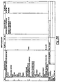
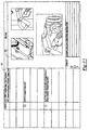
- Figures 7a-7b depict an exemplary process sheet that was generated by the process sheet module.
- This exemplary process sheet depicts the process steps associated with providing a subassembly link to an outside door handle.
- Figure 7a depicts a graphic depiction at reference numeral 400 for the step-by-step process related to the subassembly link to the outside door handle. Each step of the particular process is numbered within graphic 400 in order to better convey the assembly sequence.
- Reference numeral 415 shown in a tabular formal an association between an item with what parts are required as well as the quantity.
- the preferred embodiment utilizes three different symbols to differentiate whether a process step is directed to a process, a part, or an explanatory note.
- Legend 404 is preferably shown adjacent to the graphic to remind the user which symbol is used for which purpose.
- six steps are associated with the sub assembly link to the outside door handle.
- the present invention also includes the feature of showing a magnified view of a particular step of the process. For example, with respect to process step six, a magnified view 408 is depicted for the regular view of process step six shown at reference numeral 412 .
- Figure 7b provides the textual description for the process steps depicted on Figure 7a
- item column 420 includes six items which correspond to the six steps shown on Figure 7a.
- Figures 8a-8b depict a process sheet associated with the vehicle door assembly steps that are performed after the steps depicted in Figure 7a.
- the particular process involved with the process sheet of Figures 8a and 8b is the installation of the front door outside handle to the door.
- the subassembly link of Figure 7a is shown in Figure 8a at reference numeral 450 .
- Part information is shown at reference numeral 454 and a textual description of the process steps is provided in Figure 8b.
- Figure 9 depicts a standard work instruction exemplary data sheet.
- This exemplary standard work instruction data sheet is based upon process sheet data that is generated by the process sheet module.
- the standard work instruction data sheet contains the data in a different format in order to better suit the operations performed at a particular station.
- Legend 508 contains standard work instruction documentation information, such as, but not limited to, what changes have occurred to this particular standard work instruction sheet. Legend 508 provides the information necessary for the report to comply with ISO 9000 requirements.
- Figure 10 is a sample report depicting an additional exemplary standard work instruction report.
- the present invention as a convenience depicts within graphic window 520 several steps of the process.
- reference numerals 520 and 522 depict the process steps shown in Figure 7a.
- reference numeral 524 depicts the process step shown in Figure 8a.
- Figure 11 is a sample report depicting another exemplary standard work instruction report.
- Column 530 depicts several examples of key points being associated with certain operational steps. For example, the product regulatory point "verify correct bracket" is associated with the operational step directed to installing the accelerator.
- Graphic window 532 depicts graphics of how portions of the vehicle should appear when the assembly process has been completed.
Landscapes
- Engineering & Computer Science (AREA)
- Manufacturing & Machinery (AREA)
- Chemical & Material Sciences (AREA)
- Combustion & Propulsion (AREA)
- Transportation (AREA)
- Mechanical Engineering (AREA)
- Management, Administration, Business Operations System, And Electronic Commerce (AREA)
- Automobile Manufacture Line, Endless Track Vehicle, Trailer (AREA)
Abstract
Description
Claims (20)
- A computer-implemented system for designing and manufacturing vehicles in a distributed design environment and manufacturing plant environment, comprising:a database for storing vehicle engineering design data related to the vehicles;a process sheet data structure for interrelating the vehicle engineering design data in order to generate process sheet data that depicts the assembling process of the vehicles, said assembling process containing steps to assemble the vehicles;a manufacturing plant data structure linked to the process sheet data structure for containing assembly station data and production data for assembling the vehicles in manufacturing plants, said manufacturing plant data structure associating the station data with the process sheet data in order to indicate the assembling steps for a station contained within the manufacturing data structure;a financial data structure linked to the manufacturing plant data structure for containing financial data associated with the assembling of the vehicle in the manufacturing plants.
- The system of Claim 1 wherein the vehicle engineering design data includes part, torque, tooling, and weld data related to the assembling process.
- The system of Claim 1 further comprising:graphic files for being incorporated into the process sheet data, said graphic files visually depicting steps associated with assembling a vehicle.
- The system of Claim 1 wherein the manufacturing plant data structure includes associating the stations with resources that operate the stations.
- The system of Claim 4 further comprising:a workload balancer module for balancing the workload with respect to the stations.
- The system of Claim 4 further comprising:a workload balancer module for balancing the workload with respect to the stations using the resources that are associated with their respective stations.
- The system of Claim 4 further comprising:a workload analysis module for determining the workload with respect to the stations using the resources that are associated with their respective stations.
- The system of Claim 7 wherein the workload analysis module determines at least one station that is understaffed with respect to performing steps associated with the station.
- The system of Claim 1 wherein the process sheet data structure indicates for at least one step a predetermined assembly aspect, said predetermined assembly aspect being selected from the group consisting of safety-related assembly aspect, product regulatory-related assembly aspect, customer satisfaction-related assembly aspect, and combinations thereof.
- The system of Claim 1 further comprising:a failure analysis module for associating at least one process step with failure modes and effects data that is related to the process step.
- The system of Claim 1 further comprising:a failure analysis module for associating at least one part related to a process step with failure modes and effects data that is related to the part.
- The system of Claim 1 further comprising:related to an assembly station.a station work instruction module for generating assembly instructions
- The system of Claim 12 further comprising:a plant feedback module for associating feedback data related to an assembly step in the assembly instructions; anda computer network for transmitting the feedback data to engineers in order for the engineers to analyze the feedback data with respect to vehicle design data.
- The system of Claim 1 further comprising:a labor standards module connected to the financial data structure for determining labor costs associated with the assembling of the vehicle in the manufacturing plants.
- The system of Claim 14 further comprising:an input device for providing standard time data to the labor standards module in order for the labor standards module to determine the labor costs.
- The system of Claim 14 further comprising:an input device for providing corporate S.T.V. data to the labor standards module in order for the labor standards module to determine the labor costs.
- The system of Claim 14 further comprising:an input device for providing real-time production data of manufacturing plants to the labor standards module in order for the labor standards module to determine the labor costs associated with the manufacturing plants.
- The system of Claim 14 further comprising:an input device for providing estimated production data of manufacturing plants to the labor standards module in order for the labor standards module to determine the labor costs associated with the manufacturing plants.
- The system of Claim 1 further comprising:an input device for providing changes to vehicle engineering design data, said process sheet data structure being automatically modified based upon the changes; anda computer network for substantially automatically communicating the modified process sheet data structure to the manufacturing plants such that at least one assembly step in a manufacturing plant is modified based upon the modified process sheet data structure.
- A computer-implemented system for designing and manufacturing vehicles in a distributed design environment and manufacturing plant environment, wherein engineers generate vehicle design data, wherein plant personnel assemble vehicles at vehicle stations, said system comprising:a database for storing the vehicle engineering design data that is generated by the engineers;a process sheet data structure for interrelating the vehicle engineering design data in order to generate process sheet data that depicts the assembling process of the vehicles, said assembling process containing steps to assemble the vehicles;a manufacturing plant data structure linked to the process sheet data structure for containing assembly station data and production data for assembling the vehicles in manufacturing plants, said manufacturing plant data structure associating the station data with the process sheet data in order to indicate the assembling steps for a station contained within the manufacturing data structure;a financial data structure linked to the manufacturing plant data structure for containing financial data associated with the assembling of the vehicle in the manufacturing plants.
Applications Claiming Priority (2)
| Application Number | Priority Date | Filing Date | Title |
|---|---|---|---|
| US387956 | 1982-06-14 | ||
| US09/387,956 US6453209B1 (en) | 1999-09-01 | 1999-09-01 | Computer-implemented method and apparatus for integrating vehicle manufacturing operations |
Publications (2)
| Publication Number | Publication Date |
|---|---|
| EP1081028A2 true EP1081028A2 (en) | 2001-03-07 |
| EP1081028A3 EP1081028A3 (en) | 2003-04-02 |
Family
ID=23532020
Family Applications (1)
| Application Number | Title | Priority Date | Filing Date |
|---|---|---|---|
| EP00117763A Withdrawn EP1081028A3 (en) | 1999-09-01 | 2000-08-18 | A computer-implemented method and apparatus for integrating vehicle manufacturing operations |
Country Status (3)
| Country | Link |
|---|---|
| US (1) | US6453209B1 (en) |
| EP (1) | EP1081028A3 (en) |
| CA (1) | CA2316790A1 (en) |
Cited By (2)
| Publication number | Priority date | Publication date | Assignee | Title |
|---|---|---|---|---|
| WO2006053606A1 (en) * | 2004-11-11 | 2006-05-26 | Volkswagen Aktiengesellschaft | Method and system for manufacturing vehicles, modules and vehicle parts |
| US7136713B2 (en) | 2003-01-14 | 2006-11-14 | Motorola, Inc. | Manufacturing and de-fabrication analysis method and apparatus |
Families Citing this family (34)
| Publication number | Priority date | Publication date | Assignee | Title |
|---|---|---|---|---|
| JP2001195463A (en) * | 2000-01-06 | 2001-07-19 | Canon Inc | Work standard creation system, work standard creation method, distributed client-server system, and storage medium for computer program |
| JP2001195462A (en) * | 2000-01-06 | 2001-07-19 | Canon Inc | Assembly information management system and client-server distributed system for assembly information management |
| JP2001256333A (en) * | 2000-01-06 | 2001-09-21 | Canon Inc | Work allocation system, work allocation method, distributed client-server system, and computer program storage medium |
| JP2001195115A (en) | 2000-01-06 | 2001-07-19 | Canon Inc | Automatic man-hour setting system, automatic man-hour setting method, distributed client-server system, and storage medium for computer program |
| US7376477B2 (en) * | 2000-12-29 | 2008-05-20 | Honda Motor Co., Ltd. | Move lot size balancing system and method |
| JP2003015724A (en) * | 2001-07-03 | 2003-01-17 | Toyota Motor Corp | Computer to calculate working time group from used parts group |
| JP2003015723A (en) * | 2001-07-03 | 2003-01-17 | Toyota Motor Corp | Work distribution planning support system using visual display screen |
| AT500188B1 (en) * | 2001-09-14 | 2007-03-15 | Voest Alpine Ind Anlagen | COMPUTER-ASSISTED CONFIGURATOR FOR CONFIGURING AN INVESTMENT OF THE FOUNDRY INDUSTRY |
| CN1319115C (en) * | 2001-10-01 | 2007-05-30 | 株式会社半导体能源研究所 | System and method for producing combined products |
| US7006883B2 (en) * | 2001-10-10 | 2006-02-28 | Semiconductor Energy Laboratory Co., Ltd. | Production system for composite product and production method for manufacturing of same |
| US7035769B2 (en) * | 2001-12-26 | 2006-04-25 | Stmicroelectronics S.R.L. | Design failure mode effect analysis (DFMEA) |
| US6850904B2 (en) * | 2002-07-25 | 2005-02-01 | International Business Machines Corporation | Relational database for producing bill-of-materials from planning information |
| US6823287B2 (en) * | 2002-12-17 | 2004-11-23 | Caterpillar Inc | Method for predicting the quality of a product |
| US6990383B2 (en) * | 2003-02-03 | 2006-01-24 | Deere & Company | Infinitely variable, order specific, holistic assembly process control system |
| US7580769B2 (en) * | 2003-08-28 | 2009-08-25 | The Boeing Company | Tool operator instructions system and method |
| US20050096885A1 (en) * | 2003-11-05 | 2005-05-05 | Paccar Inc. | System and method for automating the generation of manufacturing frame designs |
| US7412632B2 (en) * | 2003-11-25 | 2008-08-12 | Ford Motor Company | Method to facilitate failure modes and effects analysis |
| US20050216429A1 (en) * | 2004-03-24 | 2005-09-29 | Hertz Michael T | System and method for collaborative systems engineering |
| US8364454B2 (en) * | 2004-07-27 | 2013-01-29 | Ford Motor Company | System and method of dynamic clearance checking using a geometric model |
| US8027745B1 (en) * | 2005-03-01 | 2011-09-27 | Electrical Controls, Inc. | Non-linear, animated, interactive assembly guide and method for controlling production |
| US20070198117A1 (en) * | 2006-02-17 | 2007-08-23 | Nasir Wajihuddin | Interactive custom design and building of toy vehicle |
| US7515974B2 (en) * | 2006-02-21 | 2009-04-07 | Honeywell International Inc. | Control system and method for compliant control of mission functions |
| AU2008337296B2 (en) * | 2007-12-18 | 2013-02-14 | Bae Systems Plc | Assisting failure mode and effects analysis of a system comprising a plurality of components |
| DE102008020083A1 (en) * | 2008-04-22 | 2009-10-29 | Dr. Ing. H.C. F. Porsche Aktiengesellschaft | Method for manufacturing motor vehicles |
| US8014886B2 (en) * | 2008-05-12 | 2011-09-06 | Ford Motor Company | Method and system for generating an assembly configuration |
| US8078443B2 (en) * | 2008-05-12 | 2011-12-13 | Ford Motor Company | Method and system for generating configuration constraints for computer models |
| CA2784912A1 (en) | 2010-02-12 | 2011-08-18 | Illinois Tool Works Inc. | Weld bank data structures for welding applications |
| JP5628083B2 (en) * | 2011-04-13 | 2014-11-19 | 株式会社日立製作所 | Computer system and assembly animation generation method |
| US11410206B2 (en) * | 2014-06-12 | 2022-08-09 | Truecar, Inc. | Systems and methods for transformation of raw data to actionable data |
| US10162342B2 (en) * | 2016-01-08 | 2018-12-25 | The Boeing Company | System and methods for managing changes to a product in a manufacturing environment including an anytime design check |
| US10048679B2 (en) | 2016-01-08 | 2018-08-14 | The Boeing Company | System and methods for managing changes to a product in a manufacturing environment including a minor model relational design |
| US10664783B2 (en) | 2016-01-08 | 2020-05-26 | The Boeing Company | System and methods for managing changes to a product in a manufacturing environment including conversion of an engineering bill of material to a manufacturing bill of material |
| US10054937B2 (en) | 2016-01-08 | 2018-08-21 | The Boeing Company | System and methods for managing changes to a product in a manufacturing environment including a bill of material pre-processor |
| CN116562614A (en) * | 2023-04-11 | 2023-08-08 | 中车唐山机车车辆有限公司 | Correlation method between rail vehicle PFMEA and MBOM |
Family Cites Families (27)
| Publication number | Priority date | Publication date | Assignee | Title |
|---|---|---|---|---|
| US4472783A (en) | 1980-07-21 | 1984-09-18 | Kearney & Trecker Corporation | Flexible manufacturing system |
| US4561060A (en) | 1982-01-29 | 1985-12-24 | Lear Siegler, Inc. | Tote director |
| US4669047A (en) | 1984-03-20 | 1987-05-26 | Clark Equipment Company | Automated parts supply system |
| US5033014A (en) | 1987-04-14 | 1991-07-16 | Northrop Corporation | Integrated manufacturing system |
| US4887218A (en) | 1987-12-01 | 1989-12-12 | International Business Machines Corporation | Automated production release system |
| US4961148A (en) | 1989-02-06 | 1990-10-02 | Chrysler Corporation | Method for preparing automotive assembly operations documents |
| US5036479A (en) | 1989-04-20 | 1991-07-30 | Trw Inc. | Modular automated avionics test system |
| JP2559847B2 (en) | 1989-04-27 | 1996-12-04 | 日産自動車株式会社 | Production line management method |
| US5212635A (en) * | 1989-10-23 | 1993-05-18 | International Business Machines Corporation | Method and apparatus for measurement of manufacturing technician efficiency |
| US5150288A (en) * | 1989-12-18 | 1992-09-22 | Honda Giken Kogyo Kabushiki Kaisha | Production management system and method of transmitting data |
| DE4113556C3 (en) | 1990-04-26 | 2000-02-24 | Mazda Motor | Production facility for controlling production processes and production control processes for production processes |
| JPH0747403B2 (en) | 1990-05-22 | 1995-05-24 | インベストロニカ・ソシエダッド・アノニマ | Program-controlled box / container operation / transfer device |
| US5255197A (en) | 1990-07-06 | 1993-10-19 | Honda Giken Kogyo Kabushiki Kaisha | Line production management system |
| US5153839A (en) | 1990-09-28 | 1992-10-06 | The Boeing Company | Wire harness manufacturing system |
| US5307261A (en) | 1991-06-28 | 1994-04-26 | International Business Machines Corporation | Method and system for product configuration management in a computer based manufacturing system |
| US5469361A (en) * | 1991-08-08 | 1995-11-21 | The Board Of Regents Acting For And On Behalf Of The University Of Michigan | Generic cell controlling method and apparatus for computer integrated manufacturing system |
| JPH05233644A (en) | 1991-12-05 | 1993-09-10 | Internatl Business Mach Corp <Ibm> | Method and system for optimizing transferring of material within computer base manufacturing system |
| US5552995A (en) | 1993-11-24 | 1996-09-03 | The Trustees Of The Stevens Institute Of Technology | Concurrent engineering design tool and method |
| US5910894A (en) | 1994-01-11 | 1999-06-08 | Sensor Adaptive Machines, Inc. | Sensor based assembly tooling improvements |
| JP3528934B2 (en) | 1994-03-29 | 2004-05-24 | マツダ株式会社 | Production equipment control device |
| US5664180A (en) * | 1995-03-20 | 1997-09-02 | Framework Technologies Corporation | Design tool for complex objects which links object structures of a design object in multiple design domains |
| WO1996036921A1 (en) | 1995-05-19 | 1996-11-21 | 3Com Corporation | Method and apparatus for linking computer aided design databases with a numerical control machine database |
| US5864482A (en) | 1996-05-06 | 1999-01-26 | Amadasoft America, Inc. | Apparatus and method for managing distributing design and manufacturing information throughout a sheet metal production facility |
| JP2780702B2 (en) | 1996-05-30 | 1998-07-30 | 日本電気株式会社 | Production control system and production control method |
| US5822716A (en) | 1996-07-22 | 1998-10-13 | Atlantic Richfield Company | System and method for generating bills of lading for liquid commodity shipments |
| US5835377A (en) | 1997-03-24 | 1998-11-10 | International Business Machines Corporation | Method and system for optimized material movement within a computer based manufacturing system utilizing global positioning systems |
| US5761093A (en) | 1997-05-08 | 1998-06-02 | Motorola, Inc. | Quality forecasting engine |
-
1999
- 1999-09-01 US US09/387,956 patent/US6453209B1/en not_active Expired - Lifetime
-
2000
- 2000-08-18 EP EP00117763A patent/EP1081028A3/en not_active Withdrawn
- 2000-08-28 CA CA002316790A patent/CA2316790A1/en not_active Abandoned
Cited By (2)
| Publication number | Priority date | Publication date | Assignee | Title |
|---|---|---|---|---|
| US7136713B2 (en) | 2003-01-14 | 2006-11-14 | Motorola, Inc. | Manufacturing and de-fabrication analysis method and apparatus |
| WO2006053606A1 (en) * | 2004-11-11 | 2006-05-26 | Volkswagen Aktiengesellschaft | Method and system for manufacturing vehicles, modules and vehicle parts |
Also Published As
| Publication number | Publication date |
|---|---|
| EP1081028A3 (en) | 2003-04-02 |
| US6453209B1 (en) | 2002-09-17 |
| CA2316790A1 (en) | 2001-03-01 |
Similar Documents
| Publication | Publication Date | Title |
|---|---|---|
| US6453209B1 (en) | Computer-implemented method and apparatus for integrating vehicle manufacturing operations | |
| Pessôa et al. | The lean product design and development journey | |
| EP1314108A1 (en) | System and method for supply chain product and process development collaboration | |
| WO2007100730A2 (en) | Engineering manufacturing analysis system | |
| CA2600656A1 (en) | Compliance manager | |
| Harun et al. | An integrated modeling method for assessment of quality systems applied to aerospace manufacturing supply chains | |
| Gullo et al. | Design for maintainability | |
| Annex et al. | National BIM Standard-United States® Version 3 | |
| CA2429511A1 (en) | Method and apparatus for managing an operation | |
| Rippy | NASA human systems integration handbook | |
| Gullo et al. | Maintainability requirements and design criteria | |
| Stengl et al. | SAP R/3 Plant Maintenance: making it work for your business | |
| US20030093243A1 (en) | Invention for use in rating performance and monitoring product development | |
| Brown | Root-cause analysis in commercial aircraft final assembly | |
| Bandyopadhyay | QS-9000 handbook: a guide to registration and audit | |
| Raap | SAP Product Lifecycle Management | |
| Lawrence et al. | Design factors for safety-critical software | |
| CN121599645A (en) | Informationized maintenance management system special for repairman room | |
| Diallo | Using discrete-event simulation to increase system capacity: a case study of an assembly plant | |
| Andersson et al. | Incorporating Maintainability into the R&D Process-Based on a Case Study of Ground Based Radar System | |
| Sirirojvisuth | Development of hybrid lifecycle cost estimating tool (hlcet) for manufacturing influenced design tradeoff | |
| Harun et al. | An integrated modelling method for assessment of manufacturing quality systems applied to aerospace manufacturing supply chains | |
| Willoughby | BMP Systems Engineering Model Using Concurrent Engineering Methods | |
| Cralley et al. | Computer Support for Conducting Supportability Trade-Offs in a Team Setting | |
| Shields et al. | Lean implementation considerations in factory operations of low volume/high complexity production systems |
Legal Events
| Date | Code | Title | Description |
|---|---|---|---|
| PUAI | Public reference made under article 153(3) epc to a published international application that has entered the european phase |
Free format text: ORIGINAL CODE: 0009012 |
|
| AK | Designated contracting states |
Kind code of ref document: A2 Designated state(s): AT BE CH CY DE DK ES FI FR GB GR IE IT LI LU MC NL PT SE |
|
| AX | Request for extension of the european patent |
Free format text: AL;LT;LV;MK;RO;SI |
|
| PUAL | Search report despatched |
Free format text: ORIGINAL CODE: 0009013 |
|
| AK | Designated contracting states |
Kind code of ref document: A3 Designated state(s): AT BE CH CY DE DK ES FI FR GB GR IE IT LI LU MC NL PT SE Designated state(s): AT BE CH CY DE DK ES FI FR GB GR IE IT LI LU MC NL PT SE |
|
| AX | Request for extension of the european patent |
Extension state: AL LT LV MK RO SI |
|
| 17P | Request for examination filed |
Effective date: 20030527 |
|
| AKX | Designation fees paid |
Designated state(s): AT DE FR GB |
|
| STAA | Information on the status of an ep patent application or granted ep patent |
Free format text: STATUS: THE APPLICATION HAS BEEN WITHDRAWN |
|
| 18W | Application withdrawn |
Effective date: 20040812 |