EP1080918A1 - Method and device for filling ink into ink cartridge - Google Patents
Method and device for filling ink into ink cartridge Download PDFInfo
- Publication number
- EP1080918A1 EP1080918A1 EP00911366A EP00911366A EP1080918A1 EP 1080918 A1 EP1080918 A1 EP 1080918A1 EP 00911366 A EP00911366 A EP 00911366A EP 00911366 A EP00911366 A EP 00911366A EP 1080918 A1 EP1080918 A1 EP 1080918A1
- Authority
- EP
- European Patent Office
- Prior art keywords
- ink
- filling
- cartridge
- ink cartridge
- supply port
- Prior art date
- Legal status (The legal status is an assumption and is not a legal conclusion. Google has not performed a legal analysis and makes no representation as to the accuracy of the status listed.)
- Granted
Links
Images




Classifications
-
- B—PERFORMING OPERATIONS; TRANSPORTING
- B41—PRINTING; LINING MACHINES; TYPEWRITERS; STAMPS
- B41J—TYPEWRITERS; SELECTIVE PRINTING MECHANISMS, i.e. MECHANISMS PRINTING OTHERWISE THAN FROM A FORME; CORRECTION OF TYPOGRAPHICAL ERRORS
- B41J2/00—Typewriters or selective printing mechanisms characterised by the printing or marking process for which they are designed
- B41J2/005—Typewriters or selective printing mechanisms characterised by the printing or marking process for which they are designed characterised by bringing liquid or particles selectively into contact with a printing material
- B41J2/01—Ink jet
- B41J2/17—Ink jet characterised by ink handling
- B41J2/175—Ink supply systems ; Circuit parts therefor
-
- B—PERFORMING OPERATIONS; TRANSPORTING
- B41—PRINTING; LINING MACHINES; TYPEWRITERS; STAMPS
- B41J—TYPEWRITERS; SELECTIVE PRINTING MECHANISMS, i.e. MECHANISMS PRINTING OTHERWISE THAN FROM A FORME; CORRECTION OF TYPOGRAPHICAL ERRORS
- B41J2/00—Typewriters or selective printing mechanisms characterised by the printing or marking process for which they are designed
- B41J2/005—Typewriters or selective printing mechanisms characterised by the printing or marking process for which they are designed characterised by bringing liquid or particles selectively into contact with a printing material
- B41J2/01—Ink jet
- B41J2/17—Ink jet characterised by ink handling
- B41J2/175—Ink supply systems ; Circuit parts therefor
- B41J2/17503—Ink cartridges
- B41J2/17506—Refilling of the cartridge
-
- B—PERFORMING OPERATIONS; TRANSPORTING
- B41—PRINTING; LINING MACHINES; TYPEWRITERS; STAMPS
- B41J—TYPEWRITERS; SELECTIVE PRINTING MECHANISMS, i.e. MECHANISMS PRINTING OTHERWISE THAN FROM A FORME; CORRECTION OF TYPOGRAPHICAL ERRORS
- B41J2/00—Typewriters or selective printing mechanisms characterised by the printing or marking process for which they are designed
- B41J2/005—Typewriters or selective printing mechanisms characterised by the printing or marking process for which they are designed characterised by bringing liquid or particles selectively into contact with a printing material
- B41J2/01—Ink jet
- B41J2/17—Ink jet characterised by ink handling
- B41J2/175—Ink supply systems ; Circuit parts therefor
- B41J2/17503—Ink cartridges
-
- B—PERFORMING OPERATIONS; TRANSPORTING
- B41—PRINTING; LINING MACHINES; TYPEWRITERS; STAMPS
- B41J—TYPEWRITERS; SELECTIVE PRINTING MECHANISMS, i.e. MECHANISMS PRINTING OTHERWISE THAN FROM A FORME; CORRECTION OF TYPOGRAPHICAL ERRORS
- B41J2/00—Typewriters or selective printing mechanisms characterised by the printing or marking process for which they are designed
- B41J2/005—Typewriters or selective printing mechanisms characterised by the printing or marking process for which they are designed characterised by bringing liquid or particles selectively into contact with a printing material
- B41J2/01—Ink jet
- B41J2/17—Ink jet characterised by ink handling
- B41J2/175—Ink supply systems ; Circuit parts therefor
- B41J2/17503—Ink cartridges
- B41J2/17513—Inner structure
-
- B—PERFORMING OPERATIONS; TRANSPORTING
- B41—PRINTING; LINING MACHINES; TYPEWRITERS; STAMPS
- B41J—TYPEWRITERS; SELECTIVE PRINTING MECHANISMS, i.e. MECHANISMS PRINTING OTHERWISE THAN FROM A FORME; CORRECTION OF TYPOGRAPHICAL ERRORS
- B41J2/00—Typewriters or selective printing mechanisms characterised by the printing or marking process for which they are designed
- B41J2/005—Typewriters or selective printing mechanisms characterised by the printing or marking process for which they are designed characterised by bringing liquid or particles selectively into contact with a printing material
- B41J2/01—Ink jet
- B41J2/17—Ink jet characterised by ink handling
- B41J2/175—Ink supply systems ; Circuit parts therefor
- B41J2/17503—Ink cartridges
- B41J2/1752—Mounting within the printer
- B41J2/17523—Ink connection
Definitions
- the present invention relates generally to a method of and apparatus of filling an ink cartridge, which supplies ink to a print head of an ink jet type recording apparatus for ejecting ink droplets in accordance with a print signal, with ink, which ink cartridge is detachably mounted on a carriage of the recording apparatus.
- a print head of an ink jet type recording apparatus connects to an ink cartridge through an ink supply passage, so that ink is supplied from the ink cartridge to the print head.
- a porous member impregnating with ink is accommodated within a housing of the ink cartridge having an air communication hole for the sake of preventing ink level from varying due to the reciprocating movement of the carriage, and the ink is supplied therefrom to the print head through an ink supply port formed on the housing.
- ink When ink is filled in the ink cartridge thus designed, it is required that ink is filled sufficiently at least in the vicinity of the ink supply port. Otherwise, air which enters the housing through the air communication hole during the printing operation of the recording apparatus may reach the ink supply port, which may cause a problem that the air at the ink supply port would block the smooth flow of ink and certain amount of ink is remained within the housing. In addition, air may enter the print head and cover nozzles which may cause the undesirable white dot phenomena in which no ink droplet is ejected through the nozzle as the ink flow is blocked by the air. Those problems would deteriorate the print quality.
- Unexamined Japanese Patent Application No. 9-39262 discloses an ink refilling technique in which ink is press-filling through an air communication hole formed in an ink cartridge.
- the air communication hole is generally designed to have a large fluid resistance in an effort to suppress evaporation of ink housed within the ink cartridge.
- the air communication hole constructed to open to ambient air via a capillary action. Therefore, it is required to take relatively long time to fill or refill ink in the ink cartridge through the air communication hole.
- ink which is remained in the air communication hole may be dried out and solidified to close the hole, thereby to stop the air intake through the air communication hole and to block ink supply through the ink supply port to the print head. This is another problem.
- the present invention was made in view of the foregoing problems and difficulties accompanying the conventional ink cartridge for an ink jet type recording apparatus. Accordingly, it is an object of the present invention to provide a method of filling ink in an ink cartridge capable of sufficiently filling ink at a short time with a high filling condition particularly in the vicinity of the ink supply port. Another object of the present invention is to provide an apparatus of filing ink in the ink cartridge suitable for performing the method of the present invention.
- ink is filled in an ink cartridge having a housing communicating with ambient air through an air communicating hole, a porous member impregnating with ink, an ink supply port, and a valve device including a valve body always urged by a spring and a valve seat abutting against the valve body, and ink is filled in the housing of the ink cartridge through the ink supply port.
- ink may be filled in the ink cartridge whole or after the housing is decompressed.
- the decompression is performed by vacuuming air within the housing through the ink supply port or through the air communication hole which communicates with the inside of the housing.
- the porous member is filled with ink by coupling air-sealably the ink supply port to an ink container which is released to ambient air.
- Ink may be compressively introduced through the ink supply port.
- Ink may be filled after the porous member is subjected to ink-philic treatment.
- the ink-philic treatment includes steps of impregnating the porous member with water, polyhydric alcohol such as ethylene alcohol or glycerin or its aqueous solution, surfactant or its aqueous solution, or their composite solution, and dehydrating and/or drying the porous member.
- the flow rate of ink filling through the ink supply port is low at a later stage of the ink filling process.
- the pressure in the interior of the ink cartridge is controlled at the ink filling process in which the ink is filled through the ink supply port.
- the pressure in the interior of the ink cartridge is increased by supplying air from the outside or by sealing the air communication hole of the ink cartridge.
- Ink is withdrawn by vacuuming from the ink supply port after the ink is filled in the ink cartridge.
- highly degassed ink may be filled in the ink cartridge.
- the method further comprises steps of, at the last stage of the ink filling process, filling highly degassed ink in the ink cartridge and thereafter exhausting ink by vacuuming through the ink supply port.
- a first type of ink having low component concentration and a second type of ink having high component concentration are prepared, and ink is filled in the order of the first ink to the second ink.
- the ink cartridge is housed within an ink filling chamber which is sealable from the outside, and the ink filling chamber is decompressed to inject ink by means of the pressure difference from ambient air.
- the method further includes steps of: housing the ink cartridge within an ink filling chamber which is sealable from the outside; performing at least one cycle of increasing the pressure in ink filling chamber; and filling ink in the ink cartridge through the ink supply port.
- the method further includes steps of: housing the ink cartridge in an ink filling chamber which is sealable from the outside; decompressing the ink filling chamber; performing at least one cycle of increasing the pressure in ink filling chamber; and decompressing the ink filling chamber to inject ink into the ink cartridge through the ink supply port by means of the pressure difference from ambient air.
- the method further includes steps of: housing the ink cartridge in an ink filling chamber which is sealable from the outside; decompressing the ink filling chamber; performing at least one cycle of increasing the pressure in ink filling chamber; and compressing ink to inject the ink into the ink cartridge through the ink supply port.
- an ink filling apparatus for filling ink in an ink cartridge includes a housing communicating with ambient air through an air communicating hole, a porous member housed in the housing for impregnating with ink, an ink supply port, and a valve device comprising a valve body always urged by a spring and a valve seat abutting against the valve body, the ink filling apparatus including a base member on which the ink cartridge is set to a predetermined position, wherein the ink filling apparatus comprises: an ink filling pipe engageable with the ink supply port of the ink cartridge while keeping airtight and communicating with ink for filling and communicating with a vacuum device for generating negative pressure, the ink filling pipe projecting from the base member by a length enough to separate the valve body from the valve seat of the valve device; and a sealing device for sealing the air communication hole of the ink cartridge.
- an ink filling apparatus for filling ink in an ink cartridge includes a housing communicating with ambient air through an air communicating hole, a porous member housed in the housing for impregnating with ink, an ink supply port, and a valve device comprising a valve body always urged by a spring and a valve seat abutting against the valve body, the ink filling apparatus including: an ink filling chamber having an ink filling region and a base member on which the ink cartridge is set to a predetermined position, wherein the ink filling apparatus comprises: an air exhausting pipe engageable with the ink supply port of the ink cartridge while keeping airtight, the exhausting pipe projecting from the base member by a length enough to separate the valve body from the valve seat of the valve device; an ink filling pipe engageable with the ink supply port of the ink cartridge while keeping airtight and communicating with an ink tank containing ink for filling, the ink filling pipe projecting from the base member by a
- the ink filling chamber communicates with an air exhausting device for decompressing the ink filling region and with ambient air through a valve.
- the valve body When the ink supply port of the ink cartridge is mounted on an ink injection tube, the valve body is pushed up by the ink injection tube to release the ink supply passage. Thereafter the ink is injected by the ink injection tube through the ink supply port, so that ink is impregnated in the porous member which is previously decompressed.
- ink can be sufficiently filled at a short time with a high filling condition particularly in the vicinity of the ink supply port.
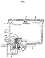
- Fig. 1 is a cross-sectional view showing an ink cartridge mounted on a carriage of a recording apparatus to which the present invention is applicable.
- an ink cartridge 1 is provided with an ink chamber 2, a porous member 2a impregnating with ink and housed in the ink chamber 2, an ink supply port 3 formed on one wall and communicating with the ink chamber 2, and an air communicating hole 1a formed on an upper wall.
- an ink supply needle 5 communicating with the print head 6 comes into engagement liquid-sealably with the ink supply port 3, so that ink in the ink chamber 2, that is, ink impregnated in the porous member 2a according to the present embodiment, is supplied to the print head 6.
- a packing 10 fitted in the ink supply port 3 is provided with a cylindrical through hole formed in the center thereof which is liquid-sealably engageable with the ink supply needle 5.
- the packing 10 is formed at the ink chamber 2 side thereof a valve seat 10a which is closed by a valve body 11 described later.
- the valve seat 10a is expanded to open by inserting the ink supply needle 5.
- a cylindrical ink introducing member 12 having an opening 12a communicating with the ink chamber 2 is fitted over the packing 10.
- the valve body 11 is disposed within the ink introducing member 12 and always urged against the valve seat 10a by a spring 13, so that the valve body 11 is slidable in an axial direction of the ink introducing member 12.
- a filter 14 is secured at an upper edge of the ink supply port 3 in such a manner that the filter 14 contacts the porous member 2a housed in the ink cartridge 1.
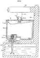
- Fig. 2 shows an ink filling apparatus according to a first embodiment of the present invention.
- An ink reservoir tank 20 is provided at an upper part thereof with a base 20a on which the ink cartridge 1 is mounted at a predetermined position.
- An ink filling pipe 21 penetrates the ink reservoir tank 20.
- the ink filling pipe 21 has an upper part which is liquid-sealably engageable with the ink supply port 3 of the ink cartridge 1 and a lower part which communicates with ink K contained in the ink reservoir tank 20.
- a tip end of the ink filling pipe 21 is tapered like the ink supply needle 5 communicating with the print head of the recording apparatus.
- An ink flow outlet 21a is formed in the tip end of the ink filling pipe 21 through which ink K is filled from the ink reservoir tank 20 to the ink cartridge 1.
- the projecting length of the ink filling pipe 21 is so adjusted that the tip end of the ink filling pipe 21 make the valve body 11 sufficiently separate from the valve seat 10a when the ink cartridge 1 is mounted on the base 20a for filling ink K.
- the ink filling apparatus is also provided with a vacuum section 22 over the ink cartridge 1 for generating negative pressure in the ink cartridge 1 through the air communicating hole 1a formed in an upper wall of the ink cartridge 1.
- the vacuum section 22 is supported by a stand 23 extending upward from a position which does not obstruct the mounting of the ink cartridge 1, in such a manner that the vacuum section 22 is slidable in a vertical direction, i.e., along an arrow A shown in Fig. 2.
- the vacuum section 22 includes at an end thereof a vacuum pipe 24 having a connecting port 24a which is resiliently abuts against the air communicating hole 1a of the ink cartridge 1 while keeping airtight and the other end of the vacuum section 22 connects to a vacuum pump not shown.
- FIGS. 3A and 3B are views showing the process of mounting the ink cartridge onto the ink filling apparatus.
- valve body 11 When the ink cartridge 1 is mounted on the carriage 4 of the recording apparatus, the valve body 11 is pushed up by the tip end of the ink supply needle 5 as shown in Fig. 1 to thereby release the ink supply passage and allow ink in the ink chamber 2 to flow out of the ink cartridge 1 to the print head 6 at an amount required for ejecting ink droplets from the nozzles.
- the ink cartridge 1 When the ink in the ink cartridge 1 is depleted, the ink cartridge 1 is detached from the carriage 4 and mounted on the ink filling apparatus shown in Fig. 2. While the depleted ink cartridge 1 is mounted on the base 20a of the ink filling apparatus, the ink supply port 3 is first accurately positioned with respect to the ink filling pipe 21 as shown in Fig. 3A and, thereafter, the ink cartridge 1 is mounted on the base 20a of the ink reservoir tank 20 as shown in Fig. 3B so that the tip end of the ink filling pipe 21 pushes the valve body 11 up against the elastic force of the spring 13 thereby to release the ink supply passage.
- the vacuum section is driven to move down while positioning the tip end of the vacuum pipe 24 with respect to the air communicating hole 1a of the ink cartridge 1, and a connecting port 24a of the vacuum pipe 24 comes into engagement liquid-sealably with the air communicating hole 1a of the ink cartridge 1.
- a vacuum pump (not shown) is activated, a negative pressure is generated in the ink chamber 2 and, accordingly, air held in the porous member 2a is exhausted through the air communicating hole 1a of the ink cartridge 1.
- the vacuum pump is deactivated to stop generating the negative pressure
- the ink cartridge 1 is detached from the ink filling pipe 21.
- the valve body 11 comes into abutment against the valve seat 10a because of the elastic force of the spring 13 as shown in Fig. 3A. Therefore, the ink supply port 3 is closed by the valve body 11 and ink is prevented from leaking out of the ink supply port 3 after the filling operation.
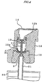
- Fig. 4 is a sectional view showing another example of an ink supply port to which the ink filling technique of the present invention is applicable.
- one wall of the opening of the ink supply port 3 at the ink chamber 2 side is formed with a slant surface 12b which enlarges toward the ink chamber 2.
- ink injected into the ink supply port 3 flows toward the porous member 2a through the slant surface 12b, ink can be filled up to far from the ink supply port 3 while air space at the opening 12a or air bubbles trapped by the filter 14 are pushed out far into the ink chamber 2.
- the present invention is not limited thereto or thereby.
- the invention may be applied to an ink cartridge for use in another type of recording apparatus in which the ink cartridge is not mounted on a carriage but a print head while the ink cartridge is mounted on a desired fixed part of the printing apparatus and ink contained in the ink cartridge is supplied to the print head through a flexible ink supply tube.
- the same performance and function can be realized as the embodiments described above.
- ink K is sucked up from the ink reservoir tank 20 while vacuuming air in the ink cartridge 1 through air communicating hole 1a.
- another process is applicable in which air in the ink cartridge 1 is exhausted out through ink supply port 3 up to a predetermined low pressure level at a first step, and then the ink cartridge 1 is connected to the ink reservoir tank 20 for filling ink at a second, subsequent step.
- the air communicating hole 1a is previously sealed by, for example, fuse-bonding a peelable film, an exhausting pipe connecting to a vacuum pump is inserted into the ink supply port 3 while keeping airtight to thereby push up the valve body 11, decompressing the interior of the ink cartridge 1, and the exhausting pipe is removed when the negative pressure in the ink cartridge 1 reaches a predetermined low level.
- the exhausting pipe is removed, the ink supply port 3 is sealed by the valve body 11 due to the elastic force of the spring 13 to maintain the low pressure condition inside the ink cartridge 1.
- the ink cartridge 1 is mounted on the ink filling apparatus and the ink filling pipe 21 communicating with the ink reservoir tank 20 is inserted into the ink supply port 3 so that ink is forced to flow into the interior of the ink cartridge 1 owing to the pressure difference between the interior of the ink cartridge 1 and that of the ink reservoir tank 20. Ink is thus filled in the ink cartridge 1.
- the ink supply port 3 performs both as an air outlet port and as an ink inlet port, the ink filling apparatus can be made simple in structure and small in size.
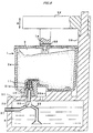
- Fig. 5 shows an ink filling apparatus according to a second embodiment of the present invention.
- the ink filling apparatus is provided with a sealing member 30 which functions to seal the air communicating hole 1a of the ink cartridge land an ink filling pipe 21 which engages liquid sealably with the ink supply port 3 of the ink cartridge 1.
- a selectively connecting device 33 is coupled to a lower end of the ink filling pipe 21, an ink communicating pipe 32 which opens to ink K contained in the ink reservoir tank 20, and a negative pressure applying pipe 31 connecting to a vacuum pump (not shown) which generates negative pressure.
- a three-way valve is employed as one example of the selectively connecting device 33.
- the valve body 11 when a depleted ink cartridge 1 is mounted on the ink filling apparatus, the valve body 11 is pushed up by ink filling pipe 21 and removed from the valve seat 10a to release the ink supply passage as shown in Figs. 2 and 3. Subsequently, the ink filling pipe 21 is communicated with the negative pressure applying pipe 31 by operating the three-way valve 33, so that negative pressure is generated in the ink chamber 2 to exhaust air from the ink chamber 2 and from the porous member 2a housed therein.
- the three-way valve 33 is operated to switch the connection of the ink filling pipe 21 to the ink communicating pipe 32, the ink K comes to flow into the ink chamber 2 and the ink cartridge is filled with ink.
- air in the ink cartridge 1 is exhausted through ink supply port 3
- air particularly in the vicinity of the ink supply port 3 can be withdrawn more assuredly and then ink can be filled particularly in the vicinity of the ink supply port 3 more assuredly.
- This is advantageous for a high quality ink cartridge in that the undesirable air flow to the print head 6 can be prevented while supplying only ink to the print head 6.
- air is exhausted independently from ink injection process. Owing to the process of the present invention, sufficiently strong negative pressure can be applied to the ink chamber 2 while taking enough time to accomplish it, and air held in the porous member 2a can be assuredly removed out.
- the porous member 2a may desirably be subjected to the hydrophilic treatment or ink-philic treatment before the ink filling process.
- the decompression process may be omitted as ink can be filled in the porous member 2a owing to the capillary action generated by the porous member 2a itself.
- Such hydrophilic treatment can be realized by impregnating porous member 2a with water, polyhydric alcohol such as ethylene glycol or glycerin or its aqueous solution, surfactant or its aqueous solution, or their composite solution and, thereafter, the porous member 2a is dehydrated and/or dried. Accordingly, the porous member 2a for the ink cartridge after the latter is depleted may be filled with ink owing to the capillary action without conducting the decompression process because the porous member 2a is still hydrophilic.
- polyhydric alcohol such as ethylene glycol or glycerin or its aqueous solution, surfactant or its aqueous solution, or their composite solution
- ink contained in the ink reservoir tank 20 is previously degassed by applying ink to air/water separating unit constructed by hollow filar membrane or contacting a zeolite such as TeflonTM thereby to remove gas dissolved in ink, so that the seepage performance of ink with respect to the porous member 2a can be improved, and the porous member 2a can readily impregnate ink entirely and uniformly.
- air/water separating unit constructed by hollow filar membrane or contacting a zeolite such as TeflonTM thereby to remove gas dissolved in ink
- ink is injected by using the low pressure within the ink cartridge or capillary action by the porous member 2a.
- degassed ink is compressed and supplied into the ink cartridge through the ink supply port by using a compression pump. The same or more improved ink filling performance can be realized by this arrangement.
- air may preferably be injected through the air communicating hole 1a or the air communicating hole 1a may be sealed by a cover or the like immediately before the completion of the ink filling process, so that air pressure within the interior space is increased.
- the ink flow rate at the beginning of the ink filling process is set to be high, for example, 10g/min.
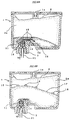
- the ink flow rate is high, air bubble 15 sticking in the filter 14 is flushed into the porous member 2a due to the strong ink flow as shown in Fig. 6A.
- the ink flow rate is high, the flow of ink injecting into the ink chamber 2 through the ink supply port 3 projecting out from the bottom wall of the ink cartridge is bent in the horizontal direction of Fig. 6A along an arrow shown in the figure because of the large flow resistance of the porous member 2a at the portion just above the ink supply port 3.
- ink turns around the ink supply port 3 to flow to the lower part of the ink supply port 3 so that ink can enter an space 16 defined by the porous member 2a and an interior wall of the ink cartridge 1.
- space 16 defined by the porous member 2a and an interior wall of the ink cartridge 1.
- the ink flow rate is changed to reduce down up to, for example, a half of the first flow rate, i.e., 5g/min.
- ink is gradually filled in the porous member 2a, and the air bubble 15 which is pushed out from the vicinity of the ink supply port 3 is carried upward by an ink wall 17 defined at the ink level as shown in Fig. 6B, and finally exhausted out through the air communicating hole 1a.
- a first type of ink which has low concentration of pigment or dye component is injected at the beginning of the ink injection process, and then a second type of ink which has high concentration of pigment or dye component is injected at the next step.
- the first ink having the low component concentration but having a easy impregnating performance can be readily impregnated within a region of the porous member 2a from the opening of the ink supply port 3 to the middle level thereof where the ink impregnating performance is relatively low at the beginning.
- the porous member 2a is wetted by the solvent of the first type of ink and turns out to be readily impregnating ink.
- the second type of ink having high component concentration is injected in place of the first type of ink.
- the second ink having high component concentration occupies the lower region of the porous member 2a in the vicinity of the ink supply port whereas the first ink having low component concentration occupies the upper region of the porous member 2a.
- the formerly separated two different types of ink are mixed up together because of the fluid diffusion phenomena, and a uniform concentration of ink suitable for printing can be accomplished.
- FIG. 7 is a perspective view showing one example of a color type ink cartridge of this type
- Figs. 8A and 8B are perspective views showing a front and a rear structures, respectively, of a memory device attached to the ink cartridge shown in Fig. 7,
- Fig. 9 is a sectional view showing the ink cartridge shown in Fig. 7 in a condition where the ink cartridge is mounted on a recording apparatus. As shown in Fig.
- an ink cartridge 40 is provided with a single, unitary housing 41 the interior of which is divided into a plurality of ink chambers, for example, five ink chambers 42a, 42b, 42c, 42d and 42e for different colors in this embodiment.
- An ink supply port 43 is formed on each of the ink chambers 42a to 42e, and a memory device 44 is attached on an outer surface of a side of the ink cartridge 40 for storing the data relating to the cartridge information mentioned above.
- the memory device 44 is provided with a circuit board 45 and electrodes 47 formed on an outer surface of the circuit board 45 and a semiconductor storage element 48 electrically connecting to the electrodes 47.
- the electrodes 47 are arranged to contact with external contact terminals 46 of the ink jet type recording apparatus.
- the ink cartridge 40 thus designed is mounted on a predetermined position of a carriage 4 of the recording apparatus as shown in Fig. 9, the electrodes 47 of the memory device 44 come into engagement with the contacts 46 formed on the carriage 4 so that data stored in the semiconductor storage element 48 is read out by the control section of the recording apparatus, and the cartridge information is updated.
- the information in the memory device 44 is updated to the latest information, in which the information such as the information during the ink filling is added.
- the recycled ink cartridge which stores the suitable information can be provided.
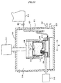
- Fig. 10 is a schematic view showing an ink filling apparatus according to a third embodiment of the present in a condition during the ink vacuum operation
- Fig. 11 is a schematic view of the ink filling apparatus shown in Fig. 10 in a condition during the ink filling operation.
- the ink filling apparatus is provided with a vacuum chamber body 51 which is sealed by a lid 50 so that an ink supply port 43 is defined. Openings 52 and 53, which connect to a vacuum pump and an ambient air releasing valve (not shown in the figures), respectively, are formed in a wall of the vacuum chamber body 51.
- a base member 56 is disposed at the bottom of the ink filling chamber 54. The base member 56 moves in a horizontal direction X by a drive mechanism 55. As shown in Figs.
- an ink filling pipe 21 connecting an ink reservoir tank 58 through a tube 57 and an air exhausting pipe 59 having the same structure as the ink filling pipe 21 and released into the ink filling chamber 54 are embedded in the base member 56 and arranged along a line in which the base member 56 moves.
- An elevating mechanism 61 having a holding arm 60 at a lower end thereof is disposed at an upper portion of the lid 50. Those component parts constitute an ink filling apparatus.
- a depleted ink cartridge 1 is held by the holding arm 60, and the base member 56 is driven to move up to a position where the air exhausting pipe 59 faces the ink supply port 3. Subsequently, when the ink cartridge 1 is elevated down until the predetermined position by the elevating mechanism 61, the air exhausting pipe 59 is inserted into the ink supply port 3 as shown in Fig. 10, and the valve body 11 of the ink cartridge 1 is pushed up by the air exhausting pipe 59 to release the interior of the ink cartridge 1.
- the ink filling chamber 54 is decompressed, and air in the ink cartridge 1 is exhausted out of the ink cartridge 1 through the ink supply port 3 at a lower portion thereof and also through the air communicating hole 1a at an upper portion thereof.
- the ink cartridge 1 is elevated up by the elevating mechanism 61 and then the base member 56 is driven to move until a predetermined position where the ink filling pipe 21 faces the ink supply port 3.
- the ink cartridge 1 is elevated down by the elevating mechanism 61 up to a predetermined position, and the ink filling pipe 21 is inserted into the ink supply port 3 as shown in Fig. 11.
- a stop valve 62 of the tube 57 constituting an ink supply passage is released so that ink contained in the ink reservoir tank 58 which is compressed by the pressure difference from the ambient air flows into the ink cartridge 1 through the ink filling pipe 21.
- a stop valve 62 of the tube 57 constituting an ink supply passage is released so that ink contained in the ink reservoir tank 58 which is compressed by the pressure difference from the ambient air flows into the ink cartridge 1 through the ink filling pipe 21.
- ink is injected into the ink cartridge after the completion of the decompression process by using the ink filling chamber 54.
- Air in the interior space of the ink cartridge or held in the porous member 2a can be assuredly withdrawn because of a pressure impact if the filling process performs the following steps, that is, the cartridge is decompressed at a first step, the pressure in the ink filling chamber 54 is increased at a second step, and the cartridge is decompressed again at a third step, in other words, if the decompression step for the ink filling is performed only after one or more cycle of air decompression and release to ambient air is conducted.
- ink is filled by the pressure difference from ambient air caused by the decompression applied to the ink filling region.
- ink may be compressed and introduced in the ink cartridge after air in the ink cartridge is withdrawn.
- the ink cartridge 1 is attached to and detached from the ink filling pipe 21 and the air exhausting pipe 59 by actuating the elevating mechanism 61 in the embodiment mentioned above.
- another arrangement may also be applicable to achieve the same operation.
- the ink cartridge is secured at a predetermined position, and the base member 56 is driven to move vertically and horizontally.
- ink is filled in an ink cartridge having a housing communicating with ambient air through an air communicating hole, a porous member impregnating with ink, an ink supply port, and a valve device including a valve body always urged by a spring and a valve seat abutting against the valve body, and ink is filled in the housing of the ink cartridge through the ink supply port. Therefore, when the ink filling pipe is set in the ink supply port to thereby push up the valve body, so that the ink supply passage is released and ink is impregnated in the porous member through the ink supply port.
- ink is injected by the ink injection tube through the ink supply port, so that ink is impregnated in the porous member which is previously decompressed. Accordingly, according to the present invention, it is realized that ink can be sufficiently filled at a short time with a high filling condition particularly in the vicinity of the ink supply port without blocking the air communication hole by ink.
Landscapes
- Ink Jet (AREA)
Abstract
Description
Claims (26)
- A method of filling an ink cartridge with ink comprising a housing which contains a porous member for impregnating with ink, an ink supply port, and a valve device comprising a valve body always urged by a spring and a valve seat abutting against the valve body, CHARACTERIZED IN THAT ink is filled in the housing of the ink cartridge through the ink supply port.
- The method of filling an ink cartridge with ink according to claim 1, CHARACTERIZED IN THAT ink is filled in the ink cartridge after the housing is decompressed.
- The method of filling an ink cartridge with ink according to claim 1, CHARACTERIZED IN THAT ink is filled in the ink cartridge while the housing is decompressed.
- The method of filling an ink cartridge with ink according to claim 2 or 3, CHARACTERIZED IN THAT the decompression is performed by vacuuming air within the housing through the air communication hole which communicates with the inside of the housing.
- The method of filling an ink cartridge with ink according to claim 2 or 3, CHARACTERIZED IN THAT the decompression is performed by vacuuming air within the housing through the ink supply port.
- The method of filling an ink cartridge with ink according to any one of claims 1 though 5, CHARACTERIZED IN THAT the porous member is filled with ink by coupling air-sealably the ink supply port to an ink container which is released to ambient air.
- The method of filling an ink cartridge with ink according to any one of claims 1 through 5, CHARACTERIZED IN THAT ink is compressively introduced through the ink supply port.
- The method of filling an ink cartridge with ink according to claim 1, CHARACTERIZED IN THAT ink is filled after the porous member is subjected to ink-philic treatment.
- The method of filling an ink cartridge with ink according to claim 8, CHARACTERIZED IN THAT said ink-philic treatment comprises steps of impregnating the porous member with water, polyhydric alcohol such as ethylene alcohol or glycerin or its aqueous solution, surfactant or its aqueous solution, or their composite solution, and dehydrating and/or drying the porous member.
- The method of filling an ink cartridge with ink according to claim 1, CHARACTERIZED IN THAT the flow rate of ink filling through the ink supply port is low at a later stage of the ink filling process.
- The method of filling an ink cartridge with ink according to claim 1, CHARACTERIZED IN THAT the pressure in the interior of the ink cartridge is controlled at the ink filling process in which the ink is filled through the ink supply port.
- The method of filling an ink cartridge with ink according to claim 11, CHARACTERIZED IN THAT the pressure in the interior of the ink cartridge is increased by supplying air from the outside.
- The method of filling an ink cartridge with ink according to claim 11, CHARACTERIZED IN THAT the pressure in the interior of the ink cartridge is increased by sealing the air communication hole of the ink cartridge.
- The method of filling an ink cartridge with ink according to claim 1, CHARACTERIZED IN THAT ink is withdrawn by vacuuming from the ink supply port after the ink is filled in the ink cartridge.
- The method of filling an ink cartridge with ink according to claim 1, CHARACTERIZED IN THAT at the last stage of the ink filling process, highly degassed ink is filled in the ink cartridge.
- The method of filling an ink cartridge with ink according to claim 15, CHARACTERIZED IN THAT the method further comprises steps of, at the last stage of the ink filling process, filling highly degassed ink in the ink cartridge and thereafter exhausting ink by vacuuming through the ink supply port.
- The method of filling an ink cartridge with ink according to claim 1, CHARACTERIZED IN THAT a first type of ink having low component concentration and a second type of ink having high component concentration are prepared, and ink is filled in the order of the first ink to the second ink.
- The method of filling an ink cartridge with ink according to claim 1, CHARACTERIZED IN THAT the ink cartridge is housed within an ink filling chamber which is sealable from the outside, and the ink filling chamber is decompressed to inject ink by means of the pressure difference from ambient air.
- The method of filling an ink cartridge with ink according to claim 1, CHARACTERIZED IN THAT the method further comprises steps of: housing the ink cartridge within an ink filling chamber which is sealable from the outside; performing at least one cycle of increasing the pressure in ink filling chamber; and filling ink in the ink cartridge through the ink supply port.
- The method of filling an ink cartridge with ink according to claim 1, CHARACTERIZED IN THAT the method further comprises steps of: housing the ink cartridge in an ink filling chamber which is sealable from the outside; decompressing the ink filling chamber; performing at least one cycle of increasing the pressure in ink filling chamber; and decompressing the ink filling chamber to inject ink into the ink cartridge through the ink supply port by means of the pressure difference from ambient air.
- The method of filling an ink cartridge with ink according to claim 1, CHARACTERIZED IN THAT the method further comprises steps of: housing the ink cartridge in an ink filling chamber which is sealable from the outside; decompressing the ink filling chamber; performing at least one cycle of increasing the pressure in ink filling chamber; and compressing ink to inject the ink into the ink cartridge through the ink supply port.
- An ink filling apparatus for filling ink in an ink cartridge comprising a housing communicating with ambient air through an air communicating hole, a porous member housed in the housing for impregnating with ink, an ink supply port, and a valve device comprising a valve body always urged by a spring and a valve seat abutting against the valve body, the ink filling apparatus including a base member on which the ink cartridge is set to a predetermined position, CHARACTERIZED IN THAT the ink filling apparatus comprises:an ink filling pipe engageable with the ink supply port of the ink cartridge while keeping airtight and communicating with ink for filling, said ink filling pipe projecting from the base member by a length enough to separate the valve body from the valve seat of the valve device; anda vacuum device for applying negative pressure to the air communication hole of the ink cartridge.
- An ink filling apparatus for filling ink in an ink cartridge comprising a housing communicating with ambient air through an air communicating hole, a porous member housed in the housing for impregnating with ink, an ink supply port, a valve device comprising a valve body always urged by a spring and a valve seat abutting against the valve body, and a detachable sealing member which seals the air communication hole, the ink filling apparatus including a base member on which the ink cartridge is set to a predetermined position, CHARACTERIZED IN THAT the ink filling apparatus comprises:an air exhausting section comprising an exhausting pipe engageable with the ink supply port of the ink cartridge while keeping airtight and communicating with a vacuum device for generating negative pressure, said exhausting pipe projecting from the base member by a length enough to separate the valve body from the valve seat of the valve device; andan ink filling section comprising an ink filling pipe engageable with the ink supply port of the ink cartridge while keeping airtight and communicating with ink for filling, said ink filling pipe projecting from the base member by a length enough to separate the valve body from the valve seat of the valve device.
- An ink filling apparatus for filling ink in an ink cartridge comprising a housing communicating with ambient air through an air communicating hole, a porous member housed in the housing for impregnating with ink, an ink supply port, and a valve device comprising a valve body always urged by a spring and a valve seat abutting against the valve body, the ink filling apparatus including a base member on which the ink cartridge is set to a predetermined position, CHARACTERIZED IN THAT the ink filling apparatus comprises:an ink filling pipe engageable with the ink supply port of the ink cartridge while keeping airtight and communicating with ink for filling and communicating with a vacuum device for generating negative pressure, said ink filling pipe projecting from the base member by a length enough to separate the valve body from the valve seat of the valve device; anda sealing device for sealing the air communication hole of the ink cartridge.
- An ink filling apparatus for filling ink in an ink cartridge comprising a housing communicating with ambient air through an air communicating hole, a porous member housed in the housing for impregnating with ink, an ink supply port, and a valve device comprising a valve body always urged by a spring and a valve seat abutting against the valve body, the ink filling apparatus including: an ink filling chamber having an ink filling region and a base member on which the ink cartridge is set to a predetermined position, CHARACTERIZED IN THAT the ink filling apparatus comprises:an air exhausting pipe engageable with the ink supply port of the ink cartridge while keeping airtight, said exhausting pipe projecting from the base member by a length enough to separate the valve body from the valve seat of the valve device;an ink filling pipe engageable with the ink supply port of the ink cartridge while keeping airtight and co1mmunicating with an ink tank containing ink for filling, said ink filling pipe projecting from the base member by a length enough to separate the valve body from the valve seat of the valve device; anda coupling device for selectively inserting said air exhausting pipe and said ink filling pipe into the ink supply port of the ink cartridge.
- The ink filling apparatus according to claim 25, CHARACTERIZED IN THAT said ink filling chamber communicates with an air exhausting device for decompressing said ink filling region and with ambient air through a valve.
Applications Claiming Priority (3)
| Application Number | Priority Date | Filing Date | Title |
|---|---|---|---|
| JP8636099 | 1999-03-29 | ||
| JP8636099 | 1999-03-29 | ||
| PCT/JP2000/001846 WO2000058100A1 (en) | 1999-03-29 | 2000-03-27 | Method and device for filling ink into ink cartridge |
Publications (3)
| Publication Number | Publication Date |
|---|---|
| EP1080918A1 true EP1080918A1 (en) | 2001-03-07 |
| EP1080918A4 EP1080918A4 (en) | 2001-12-19 |
| EP1080918B1 EP1080918B1 (en) | 2004-05-26 |
Family
ID=13884731
Family Applications (1)
| Application Number | Title | Priority Date | Filing Date |
|---|---|---|---|
| EP00911366A Expired - Lifetime EP1080918B1 (en) | 1999-03-29 | 2000-03-27 | Method and device for filling ink into ink cartridge |
Country Status (12)
| Country | Link |
|---|---|
| US (2) | US6332481B1 (en) |
| EP (1) | EP1080918B1 (en) |
| KR (1) | KR100411028B1 (en) |
| CN (1) | CN1108238C (en) |
| AT (1) | ATE267707T1 (en) |
| AU (1) | AU3328400A (en) |
| CA (1) | CA2334145C (en) |
| DE (1) | DE60010996T2 (en) |
| MY (1) | MY121880A (en) |
| SG (1) | SG103328A1 (en) |
| TW (2) | TWI247686B (en) |
| WO (1) | WO2000058100A1 (en) |
Cited By (14)
| Publication number | Priority date | Publication date | Assignee | Title |
|---|---|---|---|---|
| WO2007127278A1 (en) * | 2006-04-24 | 2007-11-08 | E. I. Du Pont De Nemours And Company | Inkjet cartridge refilling machine with improved refill process |
| WO2008055101A3 (en) * | 2006-10-30 | 2008-07-10 | Hewlett Packard Development Co | Introducing ink into an ink cartridge |
| EP1981716A4 (en) * | 2005-09-07 | 2010-01-13 | Retail Inkjet Solutions | System and method for refilling inkjet cartridges |
| WO2012062201A1 (en) * | 2010-11-09 | 2012-05-18 | 珠海天威飞马打印耗材有限公司 | Ink filling device for ink cartridge |
| CH708656A1 (en) * | 2013-10-01 | 2015-04-15 | Tandogan Siyar | Nachfüllautomat for inkjet cartridges. |
| GB2520624A (en) * | 2013-10-17 | 2015-05-27 | Canon Kk | Ink filling apparatus and ink filling method |
| EP2689932A3 (en) * | 2012-07-23 | 2015-09-16 | Seiko Epson Corporation | Refilled cartridge and method for manufacturing refilled cartridge |
| US9186901B2 (en) | 2012-07-23 | 2015-11-17 | Seiko Epson Corporation | Method for injecting printing material, injection kit, and injection device |
| US9283767B2 (en) | 2012-05-23 | 2016-03-15 | Seiko Epson Corporation | Cartridge and sealing member |
| US9308735B2 (en) | 2012-07-23 | 2016-04-12 | Seiko Epson Corporation | Cartridge |
| EP2657032A4 (en) * | 2010-12-22 | 2017-01-11 | Zhuhai Ninestar Management Co., Ltd | Ink cartridge filling device, ink cartridge filling system and corresponding method for filling ink cartridge |
| US9776418B2 (en) | 2012-07-23 | 2017-10-03 | Seiko Epson Corporation | Method and apparatus for manufacturing cartridge |
| EP2703166A3 (en) * | 2012-08-31 | 2018-06-27 | Seiko Epson Corporation | Method for manufacturing cartridge, filling kit, filling device, and cartridge |
| EP3230069A4 (en) * | 2015-01-29 | 2018-08-15 | Hewlett-Packard Development Company, L.P. | Print system with volume substantially void of liquid |
Families Citing this family (115)
| Publication number | Priority date | Publication date | Assignee | Title |
|---|---|---|---|---|
| JPH08174860A (en) * | 1994-10-26 | 1996-07-09 | Seiko Epson Corp | Ink cartridge for inkjet printer |
| JP3750138B2 (en) | 1996-02-21 | 2006-03-01 | セイコーエプソン株式会社 | Ink cartridge |
| JP4141523B2 (en) | 1997-03-19 | 2008-08-27 | セイコーエプソン株式会社 | Ink supply flow path valve device |
| ES2301888T5 (en) | 1998-07-15 | 2013-04-12 | Seiko Epson Corporation | Ink supply unit |
| SG103328A1 (en) | 1999-03-29 | 2004-04-29 | Seiko Epson Corp | Method for filling ink into ink cartridge |
| CN1278862C (en) * | 1999-10-12 | 2006-10-11 | 精工爱普生株式会社 | Ink cartridges for inkjet printing devices |
| CN101386230B (en) | 2000-01-21 | 2011-04-13 | 精工爱普生株式会社 | Ink cartridge, and ink-jet recording apparatus using the same |
| CN1184076C (en) * | 2000-02-16 | 2005-01-12 | 精工爱普生株式会社 | Ink cartridges for inkjet printers |
| US6935730B2 (en) * | 2000-04-03 | 2005-08-30 | Unicorn Image Products Co. Ltd. Of Zhuhai | One-way valve, valve unit assembly, and ink cartridge using the same |
| WO2001081238A1 (en) | 2000-04-25 | 2001-11-01 | Shell Internationale Research Maatschappij B.V. | Process and machine for mixing liquids |
| BR0110350A (en) * | 2000-04-25 | 2003-02-25 | Shell Int Research | Reusable container, process for monitoring and recording of product information when filling or refilling a reusable container, and using one or more electronic and / or optical identification means. |
| AU2001268978A1 (en) * | 2000-04-25 | 2001-11-07 | Shell Internationale Research Maatschappij B.V. | Process for the customisation of consumer products |
| AU2001252271A1 (en) * | 2000-04-25 | 2001-11-07 | Shell Internationale Research Maatschappij B.V. | A container and a process for filling said container |
| US20050243147A1 (en) * | 2000-10-12 | 2005-11-03 | Unicorn Image Products Co. Ltd. | Ink cartridge having bellows valve, ink filling method and apparatus used thereof |
| KR100487976B1 (en) | 2000-10-20 | 2005-05-10 | 세이코 엡슨 가부시키가이샤 | Ink cartridge for ink jet recording device |
| ES2275603T5 (en) * | 2000-10-20 | 2010-07-07 | Seiko Epson Corporation | INJECTION RECORD DEVICE FOR INK AND INK CARTRIDGE. |
| PT1481808E (en) * | 2000-10-20 | 2007-02-28 | Seiko Epson Corp | Ink cartridge |
| JP4521978B2 (en) * | 2000-11-08 | 2010-08-11 | キヤノン株式会社 | Ink tank, ink jet recording apparatus |
| US6604811B2 (en) * | 2000-12-15 | 2003-08-12 | Xerox Corporation | Ink jet printer having a fast acting maintenance assembly |
| JP4193435B2 (en) * | 2002-07-23 | 2008-12-10 | ブラザー工業株式会社 | Ink cartridge and ink filling method thereof |
| CA2379725C (en) * | 2001-04-03 | 2007-06-12 | Seiko Epson Corporation | Ink cartridge |
| EP1254775B1 (en) * | 2001-05-01 | 2007-02-28 | Seiko Epson Corporation | Ink tank and ink-jet printer using the same |
| ES2301584T3 (en) * | 2001-05-17 | 2008-07-01 | Seiko Epson Corporation | INK CARTRIDGE. |
| US6477956B1 (en) * | 2001-08-10 | 2002-11-12 | Sonoco Development, Inc. | Ink cartridge with self-closing valve |
| JP4779265B2 (en) * | 2001-09-07 | 2011-09-28 | Dic株式会社 | Ink filling method |
| US6796642B2 (en) * | 2001-09-19 | 2004-09-28 | Seiko Epson Corporation | Ink cartridge and its manufacturing method |
| CN100374303C (en) * | 2001-11-08 | 2008-03-12 | 精工爱普生株式会社 | Ink cartridges and recording devices |
| JP3768864B2 (en) * | 2001-11-26 | 2006-04-19 | シチズン電子株式会社 | Surface mount type light emitting diode and manufacturing method thereof |
| JP3815308B2 (en) * | 2001-11-26 | 2006-08-30 | セイコーエプソン株式会社 | Ink jet recording apparatus and ink cartridge |
| EP1336497B1 (en) * | 2002-02-14 | 2006-09-20 | Brother Kogyo Kabushiki Kaisha | Ink-jet printhead and method of manufacturing the same |
| ES2242108T3 (en) * | 2002-02-14 | 2005-11-01 | Seiko Epson Corporation | INK DEPOSIT AND INK JET PRINTER. |
| KR200278474Y1 (en) * | 2002-03-18 | 2002-06-14 | 이용수 | ink refill structure of cartridge for ink jet printer |
| ATE396872T1 (en) * | 2002-06-11 | 2008-06-15 | Seiko Epson Corp | INK CARTRIDGE |
| US7702419B2 (en) * | 2002-07-16 | 2010-04-20 | Hewlett-Packard Development Company, L.P. | System and method for filling a reservoir |
| JP3991853B2 (en) * | 2002-09-12 | 2007-10-17 | セイコーエプソン株式会社 | ink cartridge |
| JP3624950B2 (en) * | 2002-11-26 | 2005-03-02 | セイコーエプソン株式会社 | ink cartridge |
| ES2303151T3 (en) * | 2002-11-26 | 2008-08-01 | Seiko Epson Corporation | INK CARTRIDGE. |
| US6722400B1 (en) * | 2002-12-17 | 2004-04-20 | Eastman Kodak Company | Apparatus for filling and degassing a pouch |
| US6725888B1 (en) * | 2002-12-17 | 2004-04-27 | Eastman Kodak Company | Method of accurately filling and degassing a pouch |
| KR100487585B1 (en) * | 2002-12-20 | 2005-05-03 | 주식회사 프린톤 | Method of refilling ink in an ink cartridge for an inkjet printer |
| US7364279B2 (en) * | 2004-03-26 | 2008-04-29 | Brother Kogyo Kabushiki Kaisha | Ink-jet printer with air-discharge-flow assuring means |
| US8454135B2 (en) | 2003-02-04 | 2013-06-04 | Brother Kogyo Kabushiki Kaisha | Air bubble removal in an ink jet printer |
| CN100352657C (en) * | 2003-02-26 | 2007-12-05 | 付刚 | Automatic ink refilling device and method for ink cartridge of ink jet printer |
| JP4626156B2 (en) * | 2003-03-07 | 2011-02-02 | セイコーエプソン株式会社 | Liquid injection device and injection method, cartridge, and droplet discharge device |
| ITTO20030302A1 (en) * | 2003-04-17 | 2004-10-18 | Tecnost Sistemi Spa | DEVICE TO STORE AND SUPPLY SIMULTANEOUSLY |
| WO2005016647A2 (en) * | 2003-08-14 | 2005-02-24 | Nicodem Harry E | Apparatus for refilling inkjet cartridges and methods thereof |
| US7524016B2 (en) | 2004-01-21 | 2009-04-28 | Silverbrook Research Pty Ltd | Cartridge unit having negatively pressurized ink storage |
| US7448734B2 (en) | 2004-01-21 | 2008-11-11 | Silverbrook Research Pty Ltd | Inkjet printer cartridge with pagewidth printhead |
| US7367650B2 (en) | 2004-01-21 | 2008-05-06 | Silverbrook Research Pty Ltd | Printhead chip having low aspect ratio ink supply channels |
| US7469989B2 (en) | 2004-01-21 | 2008-12-30 | Silverbrook Research Pty Ltd | Printhead chip having longitudinal ink supply channels interrupted by transverse bridges |
| US20050219281A1 (en) | 2004-03-24 | 2005-10-06 | Takeo Seino | Attachment and liquid supplying |
| US20050253906A1 (en) * | 2004-05-11 | 2005-11-17 | Mcgrath Timothy R | Bulk ink feed system for inkjet printer |
| JP3977355B2 (en) | 2004-06-07 | 2007-09-19 | キヤノン株式会社 | Ink tank and recording head |
| US7159973B2 (en) * | 2004-06-10 | 2007-01-09 | Lexmark International, Inc. | Latch release mechanism for printing apparatus components |
| JP4321370B2 (en) | 2004-06-14 | 2009-08-26 | ブラザー工業株式会社 | Ink filling method |
| US7237879B2 (en) * | 2004-07-30 | 2007-07-03 | Hewlett-Packard Development Company, L.P. | Method and apparatus for reducing nozzle failure in stored inkjet printheads |
| US7344215B2 (en) * | 2004-09-28 | 2008-03-18 | E. I. Du Pont De Nemours And Company | Inkjet cartridge refilling machine and method |
| US20060092210A1 (en) * | 2004-10-29 | 2006-05-04 | Selvan Maniam | Color sensor counterfeit ink detection |
| US20060103701A1 (en) * | 2004-11-17 | 2006-05-18 | Nu-Kote International, Inc. | Ink cartridge with semiconductor storage device |
| AR051513A1 (en) * | 2004-11-29 | 2007-01-17 | Seiko Epson Corp | METHOD FOR LOADING LIQUID IN A CARTRIDGE FOR LIQUID AND CARTRIDGE LOAD |
| US7591400B2 (en) * | 2005-02-28 | 2009-09-22 | Cristian Penciu | Cartridge for dispenser of particular fluid substances |
| US7278493B2 (en) * | 2005-03-21 | 2007-10-09 | Baker Hughes Incorporated | Auto entry guide |
| JP4718888B2 (en) * | 2005-04-26 | 2011-07-06 | ゼネラルテクノロジー株式会社 | Ink cartridge regeneration method and ink filling device |
| CN100396494C (en) * | 2005-05-11 | 2008-06-25 | 关大俊 | Ink Filling Structure |
| JP2007050666A (en) * | 2005-08-19 | 2007-03-01 | Fujifilm Corp | Ink jet recording system, ink cartridge, and ink jet recording apparatus |
| JP4744243B2 (en) * | 2005-08-31 | 2011-08-10 | 富士フイルム株式会社 | Ink tank, ink jet recording apparatus, and ink filling method and apparatus |
| US7635180B2 (en) * | 2005-09-29 | 2009-12-22 | Brother Kogyo Kabushiki Kaisha | Ink cartridge |
| US7658213B1 (en) | 2005-09-29 | 2010-02-09 | Anderson Chemical Company | Fluid dispensing system |
| US7578584B2 (en) * | 2005-09-29 | 2009-08-25 | Brother Kogyo Kabushiki Kaisha | Ink cartridge |
| US7575311B2 (en) * | 2005-09-29 | 2009-08-18 | Brother Kogyo Kabushiki Kaisha | Ink cartridge |
| US7357496B2 (en) * | 2005-12-05 | 2008-04-15 | Silverbrook Research Pty Ltd | Inkjet printhead assembly with resilient ink connectors |
| US7527353B2 (en) | 2005-12-05 | 2009-05-05 | Silverbrook Research Pty Ltd | Ink cartridge with sealed air inlet |
| US7556364B2 (en) | 2005-12-05 | 2009-07-07 | Silverbrook Research Pty Ltd | Ink cartridge with self sealing outlet valve |
| US7513603B2 (en) * | 2005-12-05 | 2009-04-07 | Silverbrook Research Pty Ltd | Printhead assembly with ink inlet valve |
| US7431440B2 (en) * | 2005-12-05 | 2008-10-07 | Silverbrook Research Pty Ltd | Ink reservoir with air bag |
| US20070176981A1 (en) * | 2006-01-30 | 2007-08-02 | Shahar Turgeman | Ink jet printer cartridge refilling method and apparatus |
| US8960868B1 (en) | 2006-01-30 | 2015-02-24 | Shahar Turgeman | Ink predispense processing and cartridge fill method and apparatus |
| US9718268B1 (en) | 2006-01-30 | 2017-08-01 | Shahar Turgeman | Ink printing system comprising groups of inks, each group having a unique ink base composition |
| US8517524B1 (en) | 2006-01-30 | 2013-08-27 | Shahar Turgeman | Ink jet printer cartridge refilling method and apparatus |
| US8403466B1 (en) * | 2010-04-02 | 2013-03-26 | Shahar Turgeman | Wide format printer cartridge refilling method and apparatus |
| US10144222B1 (en) | 2006-01-30 | 2018-12-04 | Shahar Turgeman | Ink printing system |
| US20070285476A1 (en) * | 2006-04-24 | 2007-12-13 | Freire E M | Ink jet cartridge refilling machine with protected needles |
| KR100728924B1 (en) * | 2006-06-05 | 2007-06-15 | 삼성전자주식회사 | Communication method of each device in network system and network device management system |
| JP5055888B2 (en) | 2006-08-11 | 2012-10-24 | セイコーエプソン株式会社 | Method for manufacturing liquid container |
| JP5055889B2 (en) * | 2006-08-11 | 2012-10-24 | セイコーエプソン株式会社 | Method for manufacturing liquid container |
| JP4918823B2 (en) * | 2006-08-11 | 2012-04-18 | セイコーエプソン株式会社 | Method for manufacturing liquid container |
| CN100579784C (en) * | 2006-09-15 | 2010-01-13 | 财团法人工业技术研究院 | Ink jet printing head |
| US20080074479A1 (en) * | 2006-09-27 | 2008-03-27 | Tri-Century Corporation | Method and apparatus for filling ink-jet cartridge |
| US7690741B2 (en) * | 2006-10-30 | 2010-04-06 | Hewlett-Packard Development Company, L.P. | Introducing ink into an ink cartridge |
| DE102008013093A1 (en) | 2008-03-07 | 2009-09-24 | Andreas Lindfeld | Fluid i.e. ink, filling method for e.g. color inkjet printer, involves placing container present in vacuum chamber such that non-closed air exchange opening is present in fluid, where fluid and ink tank are exposed to vacuum |
| FR2939486B1 (en) * | 2008-12-09 | 2012-03-16 | Sames Technologies | VALVE FOR PROJECTING COATING PRODUCT AND PROJECTOR COMPRISING SUCH VALVE |
| JP2011073201A (en) * | 2009-09-29 | 2011-04-14 | Brother Industries Ltd | Ink filling device |
| JP5900776B2 (en) * | 2010-03-31 | 2016-04-06 | ビューティー ユニオン グローバル リミテッドBeauty Union Global Limited | Replenishment system and method |
| CN102233736B (en) * | 2010-05-01 | 2015-01-07 | 珠海纳思达企业管理有限公司 | Ink box filling device and method for filling ink in ink box by using same |
| CN201685529U (en) * | 2010-05-12 | 2010-12-29 | 珠海纳思达企业管理有限公司 | Cartridge filling device |
| CN101905568A (en) * | 2010-08-06 | 2010-12-08 | 珠海保税区天然宝杰数码科技材料有限公司 | Bubble eliminating method for inking pipe of continuous ink supply system |
| CN201784252U (en) * | 2010-08-12 | 2011-04-06 | 珠海纳思达企业管理有限公司 | Negative pressure type filling device for ink box |
| CN102371767B (en) * | 2010-08-12 | 2014-06-25 | 珠海纳思达企业管理有限公司 | Negative pressure type ink box filling apparatus, filling system thereof and filling method thereof |
| US20120176452A1 (en) * | 2011-01-12 | 2012-07-12 | Zhuhai Ninestar Management Co., Ltd. | Method for refilling ink into ink cartridge and filling tool |
| EP2692530B1 (en) * | 2011-03-31 | 2016-08-17 | Brother Kogyo Kabushiki Kaisha | Manufacturing method for recycled liquid cartridge, and manufacturing method for liquid cartridge |
| DE202011110096U1 (en) | 2011-03-31 | 2012-11-15 | Andreas Lindfeld | Device for filling reusable containers with a liquid |
| FR2973787B1 (en) * | 2011-04-11 | 2013-03-29 | Rexam Dispensing Sys | FLUID FOR DISPENSING A FLUID PRODUCT EQUIPPED WITH A FILLING VALVE |
| US8985165B2 (en) * | 2012-03-23 | 2015-03-24 | Xerox Corporation | Apparatus, method and system for carrying and dispensing an ink useful in printing |
| JP6212988B2 (en) * | 2013-06-28 | 2017-10-18 | セイコーエプソン株式会社 | Cartridge manufacturing method and cartridge manufacturing apparatus |
| JP6194658B2 (en) * | 2013-06-28 | 2017-09-13 | セイコーエプソン株式会社 | Refill cartridge manufacturing method |
| EP2783862B1 (en) | 2013-03-28 | 2019-05-08 | Brother Kogyo Kabushiki Kaisha | Liquid cartridge |
| JP6136453B2 (en) * | 2013-03-28 | 2017-05-31 | ブラザー工業株式会社 | Ink cartridge and method of manufacturing ink cartridge |
| JP6355442B2 (en) * | 2014-06-10 | 2018-07-11 | キヤノン株式会社 | Liquid filling method for liquid container |
| CN106426966B (en) * | 2015-08-03 | 2018-09-11 | 三纬国际立体列印科技股份有限公司 | A filler device for 3D prints |
| CN105711262B (en) * | 2015-12-25 | 2017-07-14 | 北海绩迅电子科技有限公司 | The ink-joiner and refilling method of a kind of ink horn of regeneration |
| JP6922258B2 (en) * | 2017-03-02 | 2021-08-18 | セイコーエプソン株式会社 | Ink replenishment container and ink replenishment system |
| FR3072326B1 (en) * | 2017-10-18 | 2019-10-25 | Societe Bic | INK MIXING DEVICE, AN ASSEMBLY COMPRISING THE DEVICE AND A METHOD OF USING THE SAME |
| JP7047452B2 (en) * | 2018-02-21 | 2022-04-05 | セイコーエプソン株式会社 | Ink connection needle, ink filling jig, cartridge |
| CN108724957B (en) * | 2018-06-11 | 2020-09-11 | 安徽天斯努信息技术股份有限公司 | Automatic ink absorbing device of ink horn for cloud printer |
| CN113733756B (en) * | 2021-09-30 | 2023-04-11 | 珠海纳思达企业管理有限公司 | Ink cartridge filling apparatus and ink cartridge filling method |
Family Cites Families (17)
| Publication number | Priority date | Publication date | Assignee | Title |
|---|---|---|---|---|
| US5844578A (en) * | 1990-01-30 | 1998-12-01 | Seiko Epson Corporation | Ink-jet recording apparatus and ink tank cartridge thereof |
| US5874976A (en) * | 1996-10-07 | 1999-02-23 | Hewlett-Packard Company | Inkjet cartridge fill port adapter |
| US5479968A (en) | 1993-08-16 | 1996-01-02 | Xerox Corporation | Ink filling apparatus and method for filling ink cartridges |
| JPH07276659A (en) * | 1994-04-13 | 1995-10-24 | Canon Inc | Ink cartridge and method for filling ink in the ink cartridge |
| DE69517637T2 (en) * | 1994-08-31 | 2001-02-15 | Canon K.K., Tokio/Tokyo | Dye refill process and device for dye containers |
| JP3713632B2 (en) * | 1994-12-28 | 2005-11-09 | 富士写真フイルム株式会社 | Ink cartridge and inkjet printer |
| JPH0939262A (en) | 1995-07-31 | 1997-02-10 | Canon Inc | Inclin refill kit |
| JPH0994978A (en) * | 1995-09-29 | 1997-04-08 | Brother Ind Ltd | Device for connecting ink supply source and inkjet head |
| US5732751A (en) * | 1995-12-04 | 1998-03-31 | Hewlett-Packard Company | Filling ink supply containers |
| US5900895A (en) * | 1995-12-04 | 1999-05-04 | Hewlett-Packard Company | Method for refilling an ink supply for an ink-jet printer |
| US5886719A (en) * | 1996-03-14 | 1999-03-23 | Hewlett-Packard Company | Ink valve having a releasable tip for a print cartridge recharge system |
| JP3666537B2 (en) | 1996-11-14 | 2005-06-29 | セイコーエプソン株式会社 | Method for manufacturing ink cartridge for ink jet recording apparatus |
| JPH10193636A (en) * | 1996-11-18 | 1998-07-28 | Mitsubishi Pencil Co Ltd | Refill ink cartridge |
| JP3287791B2 (en) | 1997-07-30 | 2002-06-04 | キヤノン株式会社 | Liquid filling method and liquid filling device for liquid container having liquid container |
| JPH1158774A (en) * | 1997-08-26 | 1999-03-02 | Seiko Epson Corp | Ink cartridge and inkjet recording device |
| JPH11207990A (en) * | 1998-01-30 | 1999-08-03 | Fuji Xerox Co Ltd | Method and unit for supplementing ink |
| SG103328A1 (en) | 1999-03-29 | 2004-04-29 | Seiko Epson Corp | Method for filling ink into ink cartridge |
-
2000
- 2000-03-27 SG SG200107764A patent/SG103328A1/en unknown
- 2000-03-27 EP EP00911366A patent/EP1080918B1/en not_active Expired - Lifetime
- 2000-03-27 AU AU33284/00A patent/AU3328400A/en not_active Abandoned
- 2000-03-27 DE DE60010996T patent/DE60010996T2/en not_active Expired - Lifetime
- 2000-03-27 CA CA002334145A patent/CA2334145C/en not_active Expired - Fee Related
- 2000-03-27 KR KR10-2000-7012081A patent/KR100411028B1/en not_active Expired - Fee Related
- 2000-03-27 WO PCT/JP2000/001846 patent/WO2000058100A1/en not_active Ceased
- 2000-03-27 CN CN00800292A patent/CN1108238C/en not_active Expired - Fee Related
- 2000-03-27 AT AT00911366T patent/ATE267707T1/en not_active IP Right Cessation
- 2000-03-28 MY MYPI20001225A patent/MY121880A/en unknown
- 2000-04-11 TW TW091114702A patent/TWI247686B/en not_active IP Right Cessation
- 2000-04-11 TW TW089105653A patent/TW520329B/en not_active IP Right Cessation
- 2000-11-29 US US09/725,022 patent/US6332481B1/en not_active Expired - Lifetime
-
2001
- 2001-07-16 US US09/904,863 patent/US6539985B2/en not_active Expired - Lifetime
Cited By (34)
| Publication number | Priority date | Publication date | Assignee | Title |
|---|---|---|---|---|
| US7980686B2 (en) | 2005-09-07 | 2011-07-19 | Retail Inkjet Solutions, Inc. | Fluid reservoir connector |
| US10011117B2 (en) | 2005-09-07 | 2018-07-03 | Retail Inkjet Solutions, Inc. | Inkjet refilling adapter |
| EP1981716A4 (en) * | 2005-09-07 | 2010-01-13 | Retail Inkjet Solutions | System and method for refilling inkjet cartridges |
| US7708370B2 (en) | 2005-09-07 | 2010-05-04 | Retail Inkjet Solutions, Inc. | Test system for an inkjet refilling station |
| US7780276B2 (en) | 2005-09-07 | 2010-08-24 | Retail Inkjet Solutions, Inc. | System for refilling inkjet cartridges |
| US7887166B2 (en) | 2005-09-07 | 2011-02-15 | Retail Inkjet Solutions, Inc. | Ink reservoir |
| US7891759B2 (en) | 2005-09-07 | 2011-02-22 | Retail Inkjet Solutions, Inc. | System for cleaning inkjet cartridges |
| US7946316B2 (en) | 2005-09-07 | 2011-05-24 | Retail Inkjet Solutions, Inc. | Inkjet refilling station |
| US9487015B2 (en) | 2005-09-07 | 2016-11-08 | Retail Inkjet Solutions, Inc. | Inkjet refilling adapter |
| US8403468B2 (en) | 2005-09-07 | 2013-03-26 | Retail Inkjet Solutions, Inc. | Modular ink cartridge refilling system |
| US8876266B2 (en) | 2005-09-07 | 2014-11-04 | Retail Inkjet Solutions, Inc. | System and method for refilling ink containers |
| US8443853B2 (en) | 2005-09-07 | 2013-05-21 | Retail Inkjet Solutions, Inc. | Inkjet refilling station |
| WO2007127278A1 (en) * | 2006-04-24 | 2007-11-08 | E. I. Du Pont De Nemours And Company | Inkjet cartridge refilling machine with improved refill process |
| WO2008055101A3 (en) * | 2006-10-30 | 2008-07-10 | Hewlett Packard Development Co | Introducing ink into an ink cartridge |
| WO2012062201A1 (en) * | 2010-11-09 | 2012-05-18 | 珠海天威飞马打印耗材有限公司 | Ink filling device for ink cartridge |
| EP2657032A4 (en) * | 2010-12-22 | 2017-01-11 | Zhuhai Ninestar Management Co., Ltd | Ink cartridge filling device, ink cartridge filling system and corresponding method for filling ink cartridge |
| US9283767B2 (en) | 2012-05-23 | 2016-03-15 | Seiko Epson Corporation | Cartridge and sealing member |
| US9186901B2 (en) | 2012-07-23 | 2015-11-17 | Seiko Epson Corporation | Method for injecting printing material, injection kit, and injection device |
| US9827776B2 (en) | 2012-07-23 | 2017-11-28 | Seiko Epson Corporation | Method and apparatus for manufacturing cartridge |
| US9308735B2 (en) | 2012-07-23 | 2016-04-12 | Seiko Epson Corporation | Cartridge |
| US10647123B2 (en) | 2012-07-23 | 2020-05-12 | Seiko Epson Corporation | Refilled cartridge and method for manufacturing refilled cartridge |
| US9475294B2 (en) | 2012-07-23 | 2016-10-25 | Seiko Epson Corporation | Method for injecting printing material, injection kit, and injection device |
| EP2689932A3 (en) * | 2012-07-23 | 2015-09-16 | Seiko Epson Corporation | Refilled cartridge and method for manufacturing refilled cartridge |
| US10384454B2 (en) | 2012-07-23 | 2019-08-20 | Seiko Epson Corporation | Refilled cartridge and method for manufacturing refilled cartridge |
| US9649847B2 (en) | 2012-07-23 | 2017-05-16 | Seiko Epson Corporation | Cartridge |
| US9776418B2 (en) | 2012-07-23 | 2017-10-03 | Seiko Epson Corporation | Method and apparatus for manufacturing cartridge |
| EP2689931A3 (en) * | 2012-07-23 | 2016-02-24 | Seiko Epson Corporation | Method for injecting printing material, injection kit, and injection device |
| EP2703166A3 (en) * | 2012-08-31 | 2018-06-27 | Seiko Epson Corporation | Method for manufacturing cartridge, filling kit, filling device, and cartridge |
| CH708656A1 (en) * | 2013-10-01 | 2015-04-15 | Tandogan Siyar | Nachfüllautomat for inkjet cartridges. |
| GB2520624A (en) * | 2013-10-17 | 2015-05-27 | Canon Kk | Ink filling apparatus and ink filling method |
| GB2520624B (en) * | 2013-10-17 | 2016-04-20 | Canon Kk | Ink filling system and ink filling method |
| EP3230069A4 (en) * | 2015-01-29 | 2018-08-15 | Hewlett-Packard Development Company, L.P. | Print system with volume substantially void of liquid |
| US10449777B2 (en) | 2015-01-29 | 2019-10-22 | Hewlett-Packard Development Company, L.P. | Print system with volume substantially void of liquid |
| US11155098B2 (en) | 2015-01-29 | 2021-10-26 | Hewlett-Packard Development Company, L.P. | Negative pressure application to a gas-filled volume |
Also Published As
| Publication number | Publication date |
|---|---|
| US6332481B1 (en) | 2001-12-25 |
| AU3328400A (en) | 2000-10-16 |
| HK1036034A1 (en) | 2001-12-21 |
| ATE267707T1 (en) | 2004-06-15 |
| DE60010996T2 (en) | 2005-06-09 |
| CN1296445A (en) | 2001-05-23 |
| MY121880A (en) | 2006-02-28 |
| EP1080918A4 (en) | 2001-12-19 |
| WO2000058100A1 (en) | 2000-10-05 |
| TWI247686B (en) | 2006-01-21 |
| DE60010996D1 (en) | 2004-07-01 |
| EP1080918B1 (en) | 2004-05-26 |
| CA2334145C (en) | 2004-03-02 |
| US20010050113A1 (en) | 2001-12-13 |
| CA2334145A1 (en) | 2000-10-05 |
| US20010052370A1 (en) | 2001-12-20 |
| CN1108238C (en) | 2003-05-14 |
| SG103328A1 (en) | 2004-04-29 |
| US6539985B2 (en) | 2003-04-01 |
| TW520329B (en) | 2003-02-11 |
| KR100411028B1 (en) | 2003-12-18 |
| KR20010043164A (en) | 2001-05-25 |
Similar Documents
| Publication | Publication Date | Title |
|---|---|---|
| US6332481B1 (en) | Method of filling an ink cartridge with ink and an apparatus thereof | |
| US7188936B2 (en) | Ink cartridge for ink jet recording apparatus, connection unit and ink jet recording apparatus | |
| EP1431040B1 (en) | Liquid cartridge | |
| US5488400A (en) | Method for refilling ink jet cartridges | |
| JP7532055B2 (en) | Liquid Supply Unit | |
| JP2000238283A (en) | Reproducing method of ink cartridge for recording apparatus | |
| US6257715B1 (en) | Ink jet printer with ink conduit gas exhaust facility and method | |
| US5686948A (en) | Method for refilling ink jet cartridges | |
| JP3314811B2 (en) | Ink cartridge filling method and apparatus | |
| JPH0920013A (en) | Ink injection method and ink injection device | |
| JP2004216866A (en) | Liquid cartridge and liquid cartridge manufacturing method | |
| JPH0939262A (en) | Inclin refill kit | |
| JPH0725025A (en) | Inkjet cartridge storage playback box | |
| JP3841173B2 (en) | Liquid cartridge and method for manufacturing liquid cartridge | |
| EP1090766A1 (en) | Ink cartridge, manufacturing method thereof, and ink jet recording apparatus | |
| JPWO2000058100A1 (en) | Method and device for filling ink cartridges with ink | |
| MXPA00011594A (en) | Method and device for filling ink into ink cartridge | |
| HK1036034B (en) | Method and device for filling ink into ink cartridge | |
| KR100505827B1 (en) | Ink refill method of ink cartridge and device thereof | |
| JP3603463B2 (en) | Ink filling method, ink cartridge manufacturing method and manufacturing apparatus | |
| JP2002103643A (en) | Ink supply mechanism for ink jet recording apparatus and ink injection tool suitable for the same | |
| KR20020088439A (en) | A equipment for refilling ink of ink cartridge | |
| HK1065750A (en) | Liquid cartridge |
Legal Events
| Date | Code | Title | Description |
|---|---|---|---|
| PUAI | Public reference made under article 153(3) epc to a published international application that has entered the european phase |
Free format text: ORIGINAL CODE: 0009012 |
|
| 17P | Request for examination filed |
Effective date: 20001107 |
|
| AK | Designated contracting states |
Kind code of ref document: A1 Designated state(s): AT BE CH CY DE DK ES FI FR GB GR IE IT LI LU MC NL PT SE |
|
| A4 | Supplementary search report drawn up and despatched |
Effective date: 20011107 |
|
| AK | Designated contracting states |
Kind code of ref document: A4 Designated state(s): AT BE CH CY DE DK ES FI FR GB GR IE IT LI LU MC NL PT SE |
|
| 17Q | First examination report despatched |
Effective date: 20020402 |
|
| GRAP | Despatch of communication of intention to grant a patent |
Free format text: ORIGINAL CODE: EPIDOSNIGR1 |
|
| GRAS | Grant fee paid |
Free format text: ORIGINAL CODE: EPIDOSNIGR3 |
|
| GRAA | (expected) grant |
Free format text: ORIGINAL CODE: 0009210 |
|
| AK | Designated contracting states |
Kind code of ref document: B1 Designated state(s): AT BE CH CY DE DK ES FI FR GB GR IE IT LI LU MC NL PT SE |
|
| PG25 | Lapsed in a contracting state [announced via postgrant information from national office to epo] |
Ref country code: IT Free format text: LAPSE BECAUSE OF FAILURE TO SUBMIT A TRANSLATION OF THE DESCRIPTION OR TO PAY THE FEE WITHIN THE PRESCRIBED TIME-LIMIT;WARNING: LAPSES OF ITALIAN PATENTS WITH EFFECTIVE DATE BEFORE 2007 MAY HAVE OCCURRED AT ANY TIME BEFORE 2007. THE CORRECT EFFECTIVE DATE MAY BE DIFFERENT FROM THE ONE RECORDED. Effective date: 20040526 Ref country code: FI Free format text: LAPSE BECAUSE OF FAILURE TO SUBMIT A TRANSLATION OF THE DESCRIPTION OR TO PAY THE FEE WITHIN THE PRESCRIBED TIME-LIMIT Effective date: 20040526 Ref country code: LI Free format text: LAPSE BECAUSE OF FAILURE TO SUBMIT A TRANSLATION OF THE DESCRIPTION OR TO PAY THE FEE WITHIN THE PRESCRIBED TIME-LIMIT Effective date: 20040526 Ref country code: NL Free format text: LAPSE BECAUSE OF FAILURE TO SUBMIT A TRANSLATION OF THE DESCRIPTION OR TO PAY THE FEE WITHIN THE PRESCRIBED TIME-LIMIT Effective date: 20040526 Ref country code: CH Free format text: LAPSE BECAUSE OF FAILURE TO SUBMIT A TRANSLATION OF THE DESCRIPTION OR TO PAY THE FEE WITHIN THE PRESCRIBED TIME-LIMIT Effective date: 20040526 Ref country code: BE Free format text: LAPSE BECAUSE OF FAILURE TO SUBMIT A TRANSLATION OF THE DESCRIPTION OR TO PAY THE FEE WITHIN THE PRESCRIBED TIME-LIMIT Effective date: 20040526 Ref country code: AT Free format text: LAPSE BECAUSE OF FAILURE TO SUBMIT A TRANSLATION OF THE DESCRIPTION OR TO PAY THE FEE WITHIN THE PRESCRIBED TIME-LIMIT Effective date: 20040526 |
|
| REG | Reference to a national code |
Ref country code: GB Ref legal event code: FG4D |
|
| REG | Reference to a national code |
Ref country code: CH Ref legal event code: EP |
|
| REG | Reference to a national code |
Ref country code: IE Ref legal event code: FG4D |
|
| REF | Corresponds to: |
Ref document number: 60010996 Country of ref document: DE Date of ref document: 20040701 Kind code of ref document: P |
|
| PG25 | Lapsed in a contracting state [announced via postgrant information from national office to epo] |
Ref country code: GR Free format text: LAPSE BECAUSE OF FAILURE TO SUBMIT A TRANSLATION OF THE DESCRIPTION OR TO PAY THE FEE WITHIN THE PRESCRIBED TIME-LIMIT Effective date: 20040826 Ref country code: DK Free format text: LAPSE BECAUSE OF FAILURE TO SUBMIT A TRANSLATION OF THE DESCRIPTION OR TO PAY THE FEE WITHIN THE PRESCRIBED TIME-LIMIT Effective date: 20040826 Ref country code: SE Free format text: LAPSE BECAUSE OF FAILURE TO SUBMIT A TRANSLATION OF THE DESCRIPTION OR TO PAY THE FEE WITHIN THE PRESCRIBED TIME-LIMIT Effective date: 20040826 |
|
| PG25 | Lapsed in a contracting state [announced via postgrant information from national office to epo] |
Ref country code: ES Free format text: LAPSE BECAUSE OF FAILURE TO SUBMIT A TRANSLATION OF THE DESCRIPTION OR TO PAY THE FEE WITHIN THE PRESCRIBED TIME-LIMIT Effective date: 20040906 |
|
| REG | Reference to a national code |
Ref country code: CH Ref legal event code: PL |
|
| NLV1 | Nl: lapsed or annulled due to failure to fulfill the requirements of art. 29p and 29m of the patents act | ||
| ET | Fr: translation filed | ||
| PG25 | Lapsed in a contracting state [announced via postgrant information from national office to epo] |
Ref country code: LU Free format text: LAPSE BECAUSE OF NON-PAYMENT OF DUE FEES Effective date: 20050327 Ref country code: CY Free format text: LAPSE BECAUSE OF FAILURE TO SUBMIT A TRANSLATION OF THE DESCRIPTION OR TO PAY THE FEE WITHIN THE PRESCRIBED TIME-LIMIT Effective date: 20050327 |
|
| PG25 | Lapsed in a contracting state [announced via postgrant information from national office to epo] |
Ref country code: IE Free format text: LAPSE BECAUSE OF NON-PAYMENT OF DUE FEES Effective date: 20050328 |
|
| PG25 | Lapsed in a contracting state [announced via postgrant information from national office to epo] |
Ref country code: MC Free format text: LAPSE BECAUSE OF NON-PAYMENT OF DUE FEES Effective date: 20050331 |
|
| PLBE | No opposition filed within time limit |
Free format text: ORIGINAL CODE: 0009261 |
|
| STAA | Information on the status of an ep patent application or granted ep patent |
Free format text: STATUS: NO OPPOSITION FILED WITHIN TIME LIMIT |
|
| 26N | No opposition filed |
Effective date: 20050301 |
|
| REG | Reference to a national code |
Ref country code: IE Ref legal event code: MM4A |
|
| PG25 | Lapsed in a contracting state [announced via postgrant information from national office to epo] |
Ref country code: PT Free format text: LAPSE BECAUSE OF NON-PAYMENT OF DUE FEES Effective date: 20041026 |
|
| REG | Reference to a national code |
Ref country code: FR Ref legal event code: PLFP Year of fee payment: 17 |
|
| REG | Reference to a national code |
Ref country code: FR Ref legal event code: PLFP Year of fee payment: 18 |
|
| REG | Reference to a national code |
Ref country code: FR Ref legal event code: PLFP Year of fee payment: 19 |
|
| PGFP | Annual fee paid to national office [announced via postgrant information from national office to epo] |
Ref country code: GB Payment date: 20180321 Year of fee payment: 19 Ref country code: DE Payment date: 20180313 Year of fee payment: 19 |
|
| PGFP | Annual fee paid to national office [announced via postgrant information from national office to epo] |
Ref country code: FR Payment date: 20180223 Year of fee payment: 19 |
|
| REG | Reference to a national code |
Ref country code: DE Ref legal event code: R119 Ref document number: 60010996 Country of ref document: DE |
|
| GBPC | Gb: european patent ceased through non-payment of renewal fee |
Effective date: 20190327 |
|
| PG25 | Lapsed in a contracting state [announced via postgrant information from national office to epo] |
Ref country code: DE Free format text: LAPSE BECAUSE OF NON-PAYMENT OF DUE FEES Effective date: 20191001 Ref country code: GB Free format text: LAPSE BECAUSE OF NON-PAYMENT OF DUE FEES Effective date: 20190327 |
|
| PG25 | Lapsed in a contracting state [announced via postgrant information from national office to epo] |
Ref country code: FR Free format text: LAPSE BECAUSE OF NON-PAYMENT OF DUE FEES Effective date: 20190331 |