EP1080759A2 - Device for swinging and rotating playing equipment - Google Patents
Device for swinging and rotating playing equipment Download PDFInfo
- Publication number
- EP1080759A2 EP1080759A2 EP00850143A EP00850143A EP1080759A2 EP 1080759 A2 EP1080759 A2 EP 1080759A2 EP 00850143 A EP00850143 A EP 00850143A EP 00850143 A EP00850143 A EP 00850143A EP 1080759 A2 EP1080759 A2 EP 1080759A2
- Authority
- EP
- European Patent Office
- Prior art keywords
- rubber
- dampening element
- movements
- plane
- dampening
- Prior art date
- Legal status (The legal status is an assumption and is not a legal conclusion. Google has not performed a legal analysis and makes no representation as to the accuracy of the status listed.)
- Granted
Links
Images


Classifications
-
- A—HUMAN NECESSITIES
- A63—SPORTS; GAMES; AMUSEMENTS
- A63G—MERRY-GO-ROUNDS; SWINGS; ROCKING-HORSES; CHUTES; SWITCHBACKS; SIMILAR DEVICES FOR PUBLIC AMUSEMENT
- A63G1/00—Roundabouts
- A63G1/32—Roundabouts with seats two or more of which form a see-saw
-
- A—HUMAN NECESSITIES
- A63—SPORTS; GAMES; AMUSEMENTS
- A63G—MERRY-GO-ROUNDS; SWINGS; ROCKING-HORSES; CHUTES; SWITCHBACKS; SIMILAR DEVICES FOR PUBLIC AMUSEMENT
- A63G1/00—Roundabouts
- A63G1/28—Roundabouts with centrifugally-swingable suspended seats
Definitions
- This invention is for a device for swinging and rotating playing equipment.
- Playing equipment of the kind for which the invention applies usually have a centre pole or mast with a rocking member mounted to rotate and swing on the top of the pole.
- the rocking member may be described as being V-shaped pointing upwards and the suspension means at the top.
- the invention has the characteristic features mentioned in claim 1.
- Other embodiments of the invention has the characteristics which are disclosed in the other claims.
- a playing equipment according to the invention for a rocking and rotating playing equipment having two arms which are fixedly connected together to an upwards pointing V-shape and which in a position of rest extend themselves from the connecting point outwards and downwards in a common vertical plane and at the point of connection are mounted on to a mounting means which allows both rotating motion and rocking motion and adjacent the mounting means there are movement limiting means which allow for wider movements at right angle to the common plane than within the plane.
- the mounting means allowing this kind of free rotating, swinging and swaying motion is a universal joint.
- the means for limiting of the movements follow along with the rotational movements of the device.
- the limiting means comprise a dampening element and a contacting element for the dampening element preferably the dampening element consists of rubber or rubber-like material and the contact element is a rigid plate.
- the dampening element consists of an oval or elliptic pad of rubber or rubber-like material
- a most preferred embodiment of this aspect is that the dampening element consists of several separate pieces of rubber or rubber-like material which are placed in a ring. Further the height of the dampening element is so adapted that its outer surface towards the contacting element is closer thereto in the common plane that in a plane at right angle thereto.
- the contact element is a plate having a convex surface turned towards the dampening element.
- the movement limiting elements have an oval or elliptic cross-section in a horizontal plane when in a position of rest.
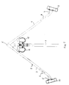
- Figure 1 is a side view of the playing equipment with the device of the invention.
- Figure 2 shows the device of the invention.
- Figure 3 is a top view of the playing equipment.
- Figures 4-6 are different views of an element included in the device of the invention.
- the playing equipment shown in figure 1 comprises a pole 1, the lower end of which is fixedly mounted to the ground or other basis at which the playing equipment is erected. At its top end the pole carries a moveable member 2 which may perform both rocking and rotating movements. In the figure the device is shown at its position of rest, unaffected by outside forces.
- the moveable member 2 has two arms 3, 4 which are joined or mounted together and which extend themselves outwards and downwards from the joint 5 which is the top point of the playing equipment.
- At each of the arms there is a seat 5, 7, a handle 6, 8 and a cushioning device 9, 10 which also forms a low back-rest at the seat.
- the movable part is mounted to the pole by means of a universal joint so that it may sway in all directions. In the rest position an imaginary common plane through the arms is in a vertical position. When the playing equipment is being used the movable member may turn so that the common plane is sloping relative to a vertical plane.
- FIG. 2 is a partial cross-sectional view of the device.
- a universal joint 16 is mounted at the top of the shaft and carries a crossbar 21 which in turn carries the arms 3, 4 of the playing equipment.
- a plate 18 which follows with the rotation of the shaft is fixedly mounted at the shaft below the universal joint.
- the plate has an upper, upwards convex part and a lower part at which a bushing 20 is mounted.
- the bushing which extends itself a distance over the outside of the pole 1, catches the devices if the shaft breaks and it protects the bearings from dust and dirt.
- damping member 17 is mounted at the underside of the plate.
- a bellow 19 extends itself from the plate 18 upwards to the crossbar 21 and the mounting plate 22 of the dampening member and protects the enclosed parts from dust and dirt.
- the dampening element 17 preferably consists of a rubber pad and cooperates with the convex surface of the plate 16 so that the movement of the moving part of the playing equipment is limited.
- the design of a preferred embodiment of the dampening element 17 is shown in the figures 4-6.
- the element is ring-shaped and in a horizontal plane it is in its entirety of oval or elliptic shape and the elastic, dampening member is preferably divided into to equal halves, one of which is shown in figures 4-6.
- the element has a flat side which is turned upwards towards the crossbar at which the element is mounted by means of a mounting plate 22. That side of the element 17 which is facing downwards towards the plate 18 is gently wave-shaped where each of the halves has a top point T which is situated in the cross-section plane of the long axis of the ellipse and two low points situsted at the short axis of the ellipse.
- the dampening element 17 and the corresponding contacting disc or plate 18 are of essentially the same elliptic or oval shape. Thereby that both them in a preferred embodiment of the invention follow along with the rotation of the shaft 15 they are always at the same vertical position relative to one another.
- the plate 18 is fixed relative to the shaft 15 while the upper element 17 is fixed relative to the upper part of the universal joint 16. Designing the dampening element in this way means that independent of the swaying and rotation of the arms 3, 4 they may in all positions get close to but not too close to the pole and so it is also prevented that any of the seats may reach to high up.
- Rubber is preferred as the material of the dampening element, mechanical steel springs and the like have turned out to be less suitable.
- the special elastic and dampening properties of rubber give the the desired limitations of the movements without sharp throws or blows to the movements. Rubber also turns out to have a long life in this application.
- Other rubber-like materials such as thermoplastic polymers may also be used. Further variations or embodiments are possible within the frame of the inventive idea.
Landscapes
- Toys (AREA)
- Vibration Prevention Devices (AREA)
- Pinball Game Machines (AREA)
- Reciprocating, Oscillating Or Vibrating Motors (AREA)
Abstract
Description
- This invention is for a device for swinging and rotating playing equipment.
- Playing equipment of the kind for which the invention applies usually have a centre pole or mast with a rocking member mounted to rotate and swing on the top of the pole. The rocking member may be described as being V-shaped pointing upwards and the suspension means at the top. By suspension in a combination of rotating shaft and universal joint, simultaneous rocking, swaying and rotating movements with great possibilities of variations are made possible. Usually this kind of playing equipment is set up outdoor with a bed of sand, rubber mat or the like.
- For safety reasons the movements must be limited so the person using the playing equipment can not be injured thereby that one of the seats gets to close to the pole or too high up. When the playing equipment is used with a bed of sand then the sand is often displaced from the area where the feet of the players or the outer ends of the moving members get into contact with the bed, the more of the sand that is displaced the closer to the pole may the players get from which follows an increasing risk for injuries. For this reason there are movement limiting means mounted adjacent the universal joint. However, this brings with it sudden changes and blows to the moving member which is experienced as unpleasant and also causes wear and damages to the playing equipment, mainly the universal joint, which brings maintenance costs with it and also may be a safety hazard.
- It is the object of the present invention to provide means to limit the movements of the moveable member without causing unpleasantness for the user or unnecessary wear of the device. The invention has the characteristic features mentioned in
claim 1. Other embodiments of the invention has the characteristics which are disclosed in the other claims. - The objects are achieved with a playing equipment according to the invention for a rocking and rotating playing equipment having two arms which are fixedly connected together to an upwards pointing V-shape and which in a position of rest extend themselves from the connecting point outwards and downwards in a common vertical plane and at the point of connection are mounted on to a mounting means which allows both rotating motion and rocking motion and adjacent the mounting means there are movement limiting means which allow for wider movements at right angle to the common plane than within the plane. The mounting means allowing this kind of free rotating, swinging and swaying motion is a universal joint. In preferred embodiments of the invention the means for limiting of the movements follow along with the rotational movements of the device. The limiting means comprise a dampening element and a contacting element for the dampening element preferably the dampening element consists of rubber or rubber-like material and the contact element is a rigid plate. In another embodiment of the invention only one of the elements follow along with the rotational movements of the device most preferably the dampening element follows along in rocking movements. Also preferred is that the dampening element consists of an oval or elliptic pad of rubber or rubber-like material, a most preferred embodiment of this aspect is that the dampening element consists of several separate pieces of rubber or rubber-like material which are placed in a ring. Further the height of the dampening element is so adapted that its outer surface towards the contacting element is closer thereto in the common plane that in a plane at right angle thereto. The contact element is a plate having a convex surface turned towards the dampening element. The movement limiting elements have an oval or elliptic cross-section in a horizontal plane when in a position of rest.
- The invention will below be described more in detail with reference to the example of embodiment which is shown in the enclosed figures.
- Figure 1 is a side view of the playing equipment with the device of the invention.
- Figure 2 shows the device of the invention.
- Figure 3 is a top view of the playing equipment.
- Figures 4-6 are different views of an element included in the device of the invention.
- The playing equipment shown in figure 1 comprises a
pole 1, the lower end of which is fixedly mounted to the ground or other basis at which the playing equipment is erected. At its top end the pole carries amoveable member 2 which may perform both rocking and rotating movements. In the figure the device is shown at its position of rest, unaffected by outside forces. Themoveable member 2 has twoarms seat handle 6, 8 and acushioning device - The mounting of the movable member to the pole is shown more in detail in figure 2 which is a partial cross-sectional view of the device. At the upper part of the pole there are two
bearings shaft 15. Auniversal joint 16 is mounted at the top of the shaft and carries acrossbar 21 which in turn carries thearms plate 18 which follows with the rotation of the shaft is fixedly mounted at the shaft below the universal joint. The plate has an upper, upwards convex part and a lower part at which abushing 20 is mounted. The bushing, which extends itself a distance over the outside of thepole 1, catches the devices if the shaft breaks and it protects the bearings from dust and dirt. At the underside of the plate there are also fastening means for twosafety chains arms universal joint 16, preferably underneath thecrossbar 21, adamping member 17 is mounted. Abellow 19 extends itself from theplate 18 upwards to thecrossbar 21 and themounting plate 22 of the dampening member and protects the enclosed parts from dust and dirt. Thedampening element 17 preferably consists of a rubber pad and cooperates with the convex surface of theplate 16 so that the movement of the moving part of the playing equipment is limited. - The design of a preferred embodiment of the
dampening element 17 is shown in the figures 4-6. The element is ring-shaped and in a horizontal plane it is in its entirety of oval or elliptic shape and the elastic, dampening member is preferably divided into to equal halves, one of which is shown in figures 4-6. The element has a flat side which is turned upwards towards the crossbar at which the element is mounted by means of amounting plate 22. That side of theelement 17 which is facing downwards towards theplate 18 is gently wave-shaped where each of the halves has a top point T which is situated in the cross-section plane of the long axis of the ellipse and two low points situsted at the short axis of the ellipse. Thedampening element 17 and the corresponding contacting disc orplate 18 are of essentially the same elliptic or oval shape. Thereby that both them in a preferred embodiment of the invention follow along with the rotation of theshaft 15 they are always at the same vertical position relative to one another. Preferably theplate 18 is fixed relative to theshaft 15 while theupper element 17 is fixed relative to the upper part of theuniversal joint 16. Designing the dampening element in this way means that independent of the swaying and rotation of thearms - Rubber is preferred as the material of the dampening element, mechanical steel springs and the like have turned out to be less suitable. The special elastic and dampening properties of rubber give the the desired limitations of the movements without sharp throws or blows to the movements. Rubber also turns out to have a long life in this application. Other rubber-like materials such as thermoplastic polymers may also be used. Further variations or embodiments are possible within the frame of the inventive idea.
Claims (12)
- Device by swinging and rotating playing equipment having two arms (3, 4) which are fixedly connected together and which in a position of rest extend themselves from the connecting point outwards and downwards in a common vertical plane and at the point of connection are mounted on to a mounting means which allows both rotating motion and rocking motion characterized in that adjacent the mounting means there are movement limiting means (17, 18) which allow for wider movements at right angle to the common plane than within the plane.
- Device according to claim 1 characterized in that the means (17, 18) for limiting of the movements follow along with the rotational movements of the device.
- Device according to claim 1 or 2 characterized in that the means comprise a dampening element (17) and a contacting element (18) for the dampening element.
- Device according to claim 3 characterized in that the the dampening element (17) consists of rubber or rubber-like material.
- Device according to claim 4 characterized in that the contact element (18) is a rigid plate.
- Device according to any of the claims 2-5 characterized in that only one of the elements follow along with the rotational movements of the device.
- Device according to claim 6 characterized in that the dampening element (17) follows along in rocking movements.
- Device according to any of the claims 3-7 characterized in that the dampening element (17) consists of an oval or elliptic pad of rubber or rubber-like material.
- Device according to any of the claims 3-7 characterized in that the dampening element (17) consists of several separate pieces of rubber or rubber-like material which are placed in a ring.
- Device according to any of the claims 3-7 characterized in that the height of the dampening element is so adapted that its outer surface towards the contacting element is closer thereto in the common plane that in a plane at right angle thereto.
- Device according to any of the claims 5-9 characterized in that the contact element is a plate having a convex surface turned towards the dampening element.
- Device according to any of the preceding claims characterized in that the movement limiting elements have an oval or elliptic cross-section in a horisontal plane when in a position of rest.
Applications Claiming Priority (2)
| Application Number | Priority Date | Filing Date | Title |
|---|---|---|---|
| SE9903120A SE517459C2 (en) | 1999-09-03 | 1999-09-03 | Device for swinging and rotating play equipment |
| SE9903120 | 1999-09-03 |
Publications (3)
| Publication Number | Publication Date |
|---|---|
| EP1080759A2 true EP1080759A2 (en) | 2001-03-07 |
| EP1080759A3 EP1080759A3 (en) | 2002-06-05 |
| EP1080759B1 EP1080759B1 (en) | 2004-10-20 |
Family
ID=20416849
Family Applications (1)
| Application Number | Title | Priority Date | Filing Date |
|---|---|---|---|
| EP00850143A Expired - Lifetime EP1080759B1 (en) | 1999-09-03 | 2000-08-28 | Device for swinging and rotating playing equipment |
Country Status (5)
| Country | Link |
|---|---|
| EP (1) | EP1080759B1 (en) |
| AT (1) | ATE279967T1 (en) |
| DE (1) | DE60015039T2 (en) |
| SE (1) | SE517459C2 (en) |
| TW (1) | TW584007U (en) |
Families Citing this family (1)
| Publication number | Priority date | Publication date | Assignee | Title |
|---|---|---|---|---|
| RU2600079C1 (en) * | 2015-04-14 | 2016-10-20 | Александр Геннадьевич Грачев | Swing |
Family Cites Families (3)
| Publication number | Priority date | Publication date | Assignee | Title |
|---|---|---|---|---|
| GB661767A (en) * | 1949-03-15 | 1951-11-28 | Hirst & Sons Ltd B | An improvement in or relating to certain amusement apparatus |
| DE8808682U1 (en) * | 1988-07-06 | 1988-11-17 | Neospiel Gesellschaft für Freizeitgeräte mbH, 3533 Willebadessen | Playground frame |
| DE3915786A1 (en) * | 1989-05-13 | 1990-11-15 | Peter Heinemann | Swing roundabout with ring-shaped tread floor - is suspended by rigid rods from turntable on top of column |
-
1999
- 1999-09-03 SE SE9903120A patent/SE517459C2/en not_active IP Right Cessation
-
2000
- 2000-08-28 DE DE60015039T patent/DE60015039T2/en not_active Expired - Lifetime
- 2000-08-28 EP EP00850143A patent/EP1080759B1/en not_active Expired - Lifetime
- 2000-08-28 AT AT00850143T patent/ATE279967T1/en not_active IP Right Cessation
- 2000-09-07 TW TW091204855U patent/TW584007U/en not_active IP Right Cessation
Non-Patent Citations (1)
| Title |
|---|
| None |
Also Published As
| Publication number | Publication date |
|---|---|
| DE60015039D1 (en) | 2004-11-25 |
| DE60015039T2 (en) | 2006-02-09 |
| EP1080759A3 (en) | 2002-06-05 |
| SE9903120D0 (en) | 1999-09-03 |
| TW584007U (en) | 2004-04-11 |
| EP1080759B1 (en) | 2004-10-20 |
| SE517459C2 (en) | 2002-06-11 |
| ATE279967T1 (en) | 2004-11-15 |
| SE9903120L (en) | 2001-03-04 |
Similar Documents
| Publication | Publication Date | Title |
|---|---|---|
| US6652424B2 (en) | Treadmill with adjustable cushioning members | |
| EP2144538B1 (en) | Swing chair | |
| WO1993011832A1 (en) | Exercise apparatus | |
| GB1570300A (en) | Shock absorber unit | |
| EP1080759B1 (en) | Device for swinging and rotating playing equipment | |
| US2527763A (en) | Rotating seesaw | |
| US20080234058A1 (en) | Rotatable teeter totter | |
| US5709002A (en) | Spherical bearing arrangement for vehicle laundry side brush | |
| US5885189A (en) | Balance beam | |
| US4925197A (en) | Pivotal creeper | |
| US6305674B1 (en) | Spring articulation structure | |
| WO1997041012A9 (en) | Spherical bearing arrangement for vehicle laundry brush | |
| CA1270012A (en) | Rotating playground equipment assembly | |
| CN102083502A (en) | exercise equipment | |
| SE518712C2 (en) | Adjustable bed | |
| CN111570992A (en) | Welding head structure for ultrasonic metal welding machine | |
| CN112459533A (en) | Building construction strutting arrangement with shock-absorbing function | |
| JP6736052B1 (en) | Bicycle training equipment | |
| CN212214576U (en) | Amusement spinner with overload protection | |
| US7377856B2 (en) | Playground apparatus | |
| US20070090672A1 (en) | Motion support apparatus | |
| US4690397A (en) | Mechanical horse for children's play | |
| CN207342189U (en) | Multi-functional seesaw | |
| EP2199119B1 (en) | Bearing element for the articulated connection of at least one control element with a vehicle part | |
| CA2285499C (en) | Suspension system for exercise apparatus |
Legal Events
| Date | Code | Title | Description |
|---|---|---|---|
| PUAI | Public reference made under article 153(3) epc to a published international application that has entered the european phase |
Free format text: ORIGINAL CODE: 0009012 |
|
| AK | Designated contracting states |
Kind code of ref document: A2 Designated state(s): AT BE CH CY DE DK ES FI FR GB GR IE IT LI LU MC NL PT SE |
|
| AX | Request for extension of the european patent |
Free format text: AL;LT;LV;MK;RO;SI |
|
| PUAL | Search report despatched |
Free format text: ORIGINAL CODE: 0009013 |
|
| AK | Designated contracting states |
Kind code of ref document: A3 Designated state(s): AT BE CH CY DE DK ES FI FR GB GR IE IT LI LU MC NL PT SE |
|
| AX | Request for extension of the european patent |
Free format text: AL;LT;LV;MK;RO;SI |
|
| RIC1 | Information provided on ipc code assigned before grant |
Free format text: 7A 63G 1/32 A, 7A 63G 1/28 B |
|
| 17P | Request for examination filed |
Effective date: 20021119 |
|
| AKX | Designation fees paid |
Designated state(s): AT BE CH CY DE DK ES FI FR GB GR IE IT LI LU MC NL PT SE |
|
| 17Q | First examination report despatched |
Effective date: 20031106 |
|
| GRAP | Despatch of communication of intention to grant a patent |
Free format text: ORIGINAL CODE: EPIDOSNIGR1 |
|
| GRAS | Grant fee paid |
Free format text: ORIGINAL CODE: EPIDOSNIGR3 |
|
| GRAA | (expected) grant |
Free format text: ORIGINAL CODE: 0009210 |
|
| RAP1 | Party data changed (applicant data changed or rights of an application transferred) |
Owner name: HAGS ANEBY AB |
|
| AK | Designated contracting states |
Kind code of ref document: B1 Designated state(s): AT BE CH CY DE DK ES FI FR GB GR IE IT LI LU MC NL PT SE |
|
| PG25 | Lapsed in a contracting state [announced via postgrant information from national office to epo] |
Ref country code: IT Free format text: LAPSE BECAUSE OF FAILURE TO SUBMIT A TRANSLATION OF THE DESCRIPTION OR TO PAY THE FEE WITHIN THE PRESCRIBED TIME-LIMIT;WARNING: LAPSES OF ITALIAN PATENTS WITH EFFECTIVE DATE BEFORE 2007 MAY HAVE OCCURRED AT ANY TIME BEFORE 2007. THE CORRECT EFFECTIVE DATE MAY BE DIFFERENT FROM THE ONE RECORDED. Effective date: 20041020 Ref country code: BE Free format text: LAPSE BECAUSE OF FAILURE TO SUBMIT A TRANSLATION OF THE DESCRIPTION OR TO PAY THE FEE WITHIN THE PRESCRIBED TIME-LIMIT Effective date: 20041020 Ref country code: CH Free format text: LAPSE BECAUSE OF FAILURE TO SUBMIT A TRANSLATION OF THE DESCRIPTION OR TO PAY THE FEE WITHIN THE PRESCRIBED TIME-LIMIT Effective date: 20041020 Ref country code: LI Free format text: LAPSE BECAUSE OF FAILURE TO SUBMIT A TRANSLATION OF THE DESCRIPTION OR TO PAY THE FEE WITHIN THE PRESCRIBED TIME-LIMIT Effective date: 20041020 Ref country code: AT Free format text: LAPSE BECAUSE OF FAILURE TO SUBMIT A TRANSLATION OF THE DESCRIPTION OR TO PAY THE FEE WITHIN THE PRESCRIBED TIME-LIMIT Effective date: 20041020 Ref country code: FI Free format text: LAPSE BECAUSE OF FAILURE TO SUBMIT A TRANSLATION OF THE DESCRIPTION OR TO PAY THE FEE WITHIN THE PRESCRIBED TIME-LIMIT Effective date: 20041020 Ref country code: NL Free format text: LAPSE BECAUSE OF FAILURE TO SUBMIT A TRANSLATION OF THE DESCRIPTION OR TO PAY THE FEE WITHIN THE PRESCRIBED TIME-LIMIT Effective date: 20041020 |
|
| REG | Reference to a national code |
Ref country code: GB Ref legal event code: FG4D |
|
| REG | Reference to a national code |
Ref country code: CH Ref legal event code: EP |
|
| REG | Reference to a national code |
Ref country code: IE Ref legal event code: FG4D |
|
| REF | Corresponds to: |
Ref document number: 60015039 Country of ref document: DE Date of ref document: 20041125 Kind code of ref document: P |
|
| PG25 | Lapsed in a contracting state [announced via postgrant information from national office to epo] |
Ref country code: DK Free format text: LAPSE BECAUSE OF FAILURE TO SUBMIT A TRANSLATION OF THE DESCRIPTION OR TO PAY THE FEE WITHIN THE PRESCRIBED TIME-LIMIT Effective date: 20050120 Ref country code: SE Free format text: LAPSE BECAUSE OF FAILURE TO SUBMIT A TRANSLATION OF THE DESCRIPTION OR TO PAY THE FEE WITHIN THE PRESCRIBED TIME-LIMIT Effective date: 20050120 Ref country code: GR Free format text: LAPSE BECAUSE OF FAILURE TO SUBMIT A TRANSLATION OF THE DESCRIPTION OR TO PAY THE FEE WITHIN THE PRESCRIBED TIME-LIMIT Effective date: 20050120 |
|
| PG25 | Lapsed in a contracting state [announced via postgrant information from national office to epo] |
Ref country code: ES Free format text: LAPSE BECAUSE OF FAILURE TO SUBMIT A TRANSLATION OF THE DESCRIPTION OR TO PAY THE FEE WITHIN THE PRESCRIBED TIME-LIMIT Effective date: 20050131 |
|
| REG | Reference to a national code |
Ref country code: CH Ref legal event code: PL |
|
| NLV1 | Nl: lapsed or annulled due to failure to fulfill the requirements of art. 29p and 29m of the patents act | ||
| PLBE | No opposition filed within time limit |
Free format text: ORIGINAL CODE: 0009261 |
|
| STAA | Information on the status of an ep patent application or granted ep patent |
Free format text: STATUS: NO OPPOSITION FILED WITHIN TIME LIMIT |
|
| PG25 | Lapsed in a contracting state [announced via postgrant information from national office to epo] |
Ref country code: CY Free format text: LAPSE BECAUSE OF FAILURE TO SUBMIT A TRANSLATION OF THE DESCRIPTION OR TO PAY THE FEE WITHIN THE PRESCRIBED TIME-LIMIT Effective date: 20050828 |
|
| PG25 | Lapsed in a contracting state [announced via postgrant information from national office to epo] |
Ref country code: IE Free format text: LAPSE BECAUSE OF NON-PAYMENT OF DUE FEES Effective date: 20050829 |
|
| PG25 | Lapsed in a contracting state [announced via postgrant information from national office to epo] |
Ref country code: LU Free format text: LAPSE BECAUSE OF NON-PAYMENT OF DUE FEES Effective date: 20050831 Ref country code: MC Free format text: LAPSE BECAUSE OF NON-PAYMENT OF DUE FEES Effective date: 20050831 |
|
| ET | Fr: translation filed | ||
| 26N | No opposition filed |
Effective date: 20050721 |
|
| REG | Reference to a national code |
Ref country code: IE Ref legal event code: MM4A |
|
| PG25 | Lapsed in a contracting state [announced via postgrant information from national office to epo] |
Ref country code: PT Free format text: LAPSE BECAUSE OF NON-PAYMENT OF DUE FEES Effective date: 20050320 |
|
| PGFP | Annual fee paid to national office [announced via postgrant information from national office to epo] |
Ref country code: FR Payment date: 20140813 Year of fee payment: 15 |
|
| PGFP | Annual fee paid to national office [announced via postgrant information from national office to epo] |
Ref country code: DE Payment date: 20150804 Year of fee payment: 16 |
|
| REG | Reference to a national code |
Ref country code: FR Ref legal event code: ST Effective date: 20160429 |
|
| PG25 | Lapsed in a contracting state [announced via postgrant information from national office to epo] |
Ref country code: FR Free format text: LAPSE BECAUSE OF NON-PAYMENT OF DUE FEES Effective date: 20150831 |
|
| REG | Reference to a national code |
Ref country code: DE Ref legal event code: R119 Ref document number: 60015039 Country of ref document: DE |
|
| PG25 | Lapsed in a contracting state [announced via postgrant information from national office to epo] |
Ref country code: DE Free format text: LAPSE BECAUSE OF NON-PAYMENT OF DUE FEES Effective date: 20170301 |
|
| PGFP | Annual fee paid to national office [announced via postgrant information from national office to epo] |
Ref country code: GB Payment date: 20190722 Year of fee payment: 20 |
|
| REG | Reference to a national code |
Ref country code: GB Ref legal event code: PE20 Expiry date: 20200827 |
|
| PG25 | Lapsed in a contracting state [announced via postgrant information from national office to epo] |
Ref country code: GB Free format text: LAPSE BECAUSE OF EXPIRATION OF PROTECTION Effective date: 20200827 |