EP1080705A2 - Thermal cover member for delivering fluid to a patient - Google Patents
Thermal cover member for delivering fluid to a patient Download PDFInfo
- Publication number
- EP1080705A2 EP1080705A2 EP00650099A EP00650099A EP1080705A2 EP 1080705 A2 EP1080705 A2 EP 1080705A2 EP 00650099 A EP00650099 A EP 00650099A EP 00650099 A EP00650099 A EP 00650099A EP 1080705 A2 EP1080705 A2 EP 1080705A2
- Authority
- EP
- European Patent Office
- Prior art keywords
- fluid
- cover member
- cell
- patient
- canopy
- Prior art date
- Legal status (The legal status is an assumption and is not a legal conclusion. Google has not performed a legal analysis and makes no representation as to the accuracy of the status listed.)
- Granted
Links
Images


Classifications
-
- A—HUMAN NECESSITIES
- A61—MEDICAL OR VETERINARY SCIENCE; HYGIENE
- A61F—FILTERS IMPLANTABLE INTO BLOOD VESSELS; PROSTHESES; DEVICES PROVIDING PATENCY TO, OR PREVENTING COLLAPSING OF, TUBULAR STRUCTURES OF THE BODY, e.g. STENTS; ORTHOPAEDIC, NURSING OR CONTRACEPTIVE DEVICES; FOMENTATION; TREATMENT OR PROTECTION OF EYES OR EARS; BANDAGES, DRESSINGS OR ABSORBENT PADS; FIRST-AID KITS
- A61F7/00—Heating or cooling appliances for medical or therapeutic treatment of the human body
- A61F2007/0059—Heating or cooling appliances for medical or therapeutic treatment of the human body with an open fluid circuit
- A61F2007/006—Heating or cooling appliances for medical or therapeutic treatment of the human body with an open fluid circuit of gas
-
- A—HUMAN NECESSITIES
- A61—MEDICAL OR VETERINARY SCIENCE; HYGIENE
- A61F—FILTERS IMPLANTABLE INTO BLOOD VESSELS; PROSTHESES; DEVICES PROVIDING PATENCY TO, OR PREVENTING COLLAPSING OF, TUBULAR STRUCTURES OF THE BODY, e.g. STENTS; ORTHOPAEDIC, NURSING OR CONTRACEPTIVE DEVICES; FOMENTATION; TREATMENT OR PROTECTION OF EYES OR EARS; BANDAGES, DRESSINGS OR ABSORBENT PADS; FIRST-AID KITS
- A61F7/00—Heating or cooling appliances for medical or therapeutic treatment of the human body
- A61F7/0097—Blankets with active heating or cooling sources
Definitions
- the present invention is directed to a thermal cover member for delivering a fluid such as air to a patient's body and more particularly for providing a plurality of cells that form fluidic spaces across the patient's body while optionally providing the ability to visually monitor the temperature and the patient skin response under the fluidic spaces.
- U.S. Patent No. 3,757,366 teaches providing heated air through a cushion device that can be positioned beneath the body of the user.
- U.S. Patent No. 3,778,851 is an example of a mattress that could be used for treating a patient who has undergone surgery, or is recovering from severe burns.
- a series of welded seams can divide the mattress into rib conduits that communicate with a peripheral manifold. Apertures in the ribs permit the egress of air, while supplemental resilient foam plastic material can be positioned within the ribs and a manifold.
- U.S. Patent No. 3,881,477 discloses a rectangular hollow tubular structure that is positioned above a patient to deliver a stream or curtain of air in upper and downward directions to create a super-atmospheric pressure zone about the patient's body for a surgical field so that it is isolated from outside air and airborne foreign particles.
- U.S. Patent No. 3,908,655 discloses a post-operative cooling device that can encompass the head and neck of a patient.
- the medical profession has been well aware of post-operative hypothermia that can be experienced by a significant number of patients that have undergone surgery.
- the art is still seeking to optimize a relatively inexpensive and disposable device to address these issues, plus providing an option of easily monitoring the temperature of fluid applied to the patent.
- the present invention provides a thermal cover member for delivering a fluid, such as heated or cooled air, to a patient's body.
- the cover member includes a hollow housing member having an inlet port for connection with a source of pressurized fluid, such as an air heater.
- the hollow housing member can include a first flexible member and a second flexible member connected together to provide a manifold conduit with a plurality of cells positioned about the housing member to create fluidic spaces or zones.
- the manifold conduit is expandable when pressurized by the fluid.
- Each cell includes a non-inflatable canopy that has a continuous perimeter sealingly connected to the housing member or manifold conduit.
- the housing member can have a plurality of exit ports communicating with each cell to provide an egress of fluid to create a fluidic space in each cell beneath each canopy to bathe a portion of the patient's body with fluid for temperature control purposes.
- the cells can be dimensioned to accommodate anatomical characteristics of a particular patient by size and sex.
- the exit ports on the perimeter side walls of the cell, that are part of the manifold conduit, can direct egressing fluid into the interior of the fluidic spaces to provide a controlled temperature zone to the body of the patient.
- the first flexible member and the second flexible member preferably includes plastic and can be heat-welded together to form continuous, seam-sealed connections about each canopy.
- the canopy can also support a thermo-chromatic indicator to visually indicate the temperature of the fluidic space in each cell and/or can include a transparent window to enable a visual monitoring of the patient's skin.
- a cover member for delivering fluid to the patient is a disposable flexible body member that can expand to provide a manifold conduit for delivery of fluid to the patient.
- a thermo-chromatic detector can be operatively connected to this cover member for providing a visible indicator of the temperature of the fluid.
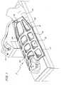
- a thermal cover member 2 of the present invention is disclosed in a post-operative situation covering a patient's body.
- the cover member 2 is disclosed in an inflated condition of being pressurized by a fluid, such as heated air from a hot air heater 4 that is connected to the cover member 2 by a flexible conduit 6.
- a hot air heater such as disclosed in U.S. Patent No. 5,785,723 and incorporated herein by reference can be used. While a hot air heater 4 is disclosed, it is also possible to use an air cooler, alternative sources of fluid, such as an oxygen-rich gas for burn victims, and/or an air sterilizer for specific treatment to the patient with the same cover member of the present invention. Additional medicinal vapors can be optionally added to the fluid.
- a hot air flow usually within a temperature range of 36° to 42° C is provided to the cover member 2.
- the cover member 2 is inflated as a result of the pressurized air providing a pressure of 1.5 centimeters of water with a delivery rate of 60 cubic feet of air per minute.
- An inlet port 12 can be detachably connected to a nozzle of the flexible conduit 6 in a conventional manner to supply the pressurized air.
- the thermal cover member 2 includes a hollow housing member, or manifold conduit 8.
- a portion of the manifold conduit 8 surrounds or encircles a periphery of the hollow housing member as a peripheral manifold conduit 10.
- Intermediate manifold conduits can extend longitudinally and traversely between the peripheral manifold conduit 10 to help define temperature zones above the patient's body.
- a cover flap 14 extends from the lower end of the thermal cover member 2 to cover the patient's feet.
- the cover flap 14 can be a non-inflatable extension of the thermal cover member 2.
- the end of the thermal cover member 2, proximal the head of the patient, has an appropriate indent to accommodate the patient's neck and head.
- a matrix of cells 16 of different sizes are positioned across and about the housing member.
- Each cell 16 includes a non-inflatable canopy 18 with a continuous seam perimeter sealingly connected to the housing member or manifold conduit 8.
- the particular configuration and size of the canopy and the corresponding cells can be subjectively arranged to accommodate the anatomical features of the human body. For example, a female patient with breasts could have an appropriate cell arranged to deliver heated air in a fluidic space beneath the canopy of that cell to her chest.
- the periphery of each cell is further formed by the interior walls of the manifold conduit 8 and is fluid permeable to permit an egress of fluid into each fluidic space beneath a canopy.
- a series of perforations or holes 20 can surround a continuous seam-sealed perimeter 22.
- the holes are positioned on the sides and not the bottom of the interior walls and direct the fluid in streams that are approximately parallel to the canopy for mixing in the cell. By providing the holes on the sides instead of the bottom, those holes will not be blocked by contacting the patient's body. Thus, a more controlled back pressure will be experienced with an even distribution of fluid.
- the cover member has a flexible body member that can be formed from a first flexible member 24 and a second flexible member 26.
- the flexible body member when not subject to fluid pressure, resembles a flat, two-ply sheet configuration.
- the first flexible member 24 and the second flexible member 26 can be formed from a spun-bound polypropylene sheet coated with a 0.5 mil of a low density polyethylene.
- the sheets are liquid-proof and have a weight of approximately one ounce per square yard.
- the polyethylene coated sides of the respective first flexible member 24 and second flexible member 26 are positioned to overlay each other and during manufacturing an application of heat by a platen (not shown) can define an outer continuous sealed-seam perimeter of the hollow housing member, and also interior, continuous sealed-seam perimeter of the individual sizes of the plurality of cells positioned about the housing member.
- Each cell 16 can have a continuous scaled perimeter seam that is heat-sealed together.
- Perforations in the lower or second flexible member 26 adjacent the continuous sealed seam perimeter 22, shown in Figure 3 provide egress for pressurized fluid to flow into the cells. By varying the size of the perforations 20, for example if the perforations are circular than by varying the diameter of the hole, the amount of fluid flow into a cell can be controlled.
- Alternative forms of other material, such as paper and plastic can be used. In one embodiment of the present invention shown in Figure 6, transparent sheets of plastic can be used to permit an observation of the patient's skin.
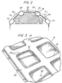
- FIG. 2 a cross sectional view of the thermal cover member 2 is shown in an inflated state.
- Respective first flexible member 24 and second flexible member 26 are expanded by the pressurized fluid so that the peripheral manifold conduit 10 and intermediate longitudinal conduits 28 and 30 are expanded.
- the canopies 18 that form the top of each cell 16 do not expand since the continuous sealed perimeter 22 around each cell 16 isolates the canopies 18 and leaves them in a flat relatively planar configuration in an intermediate position between the conduits. If these canopies 18 are transparent, it is easy to maintain a visual monitoring of the patient's body.
- manufacturing is facilitated, however the canopy can be raised or lowered, depending on the desired volume of the fluidic space.
- the individual cells 16 define fluidic spaces in the cavity beneath each cell and they are bounded by the sealed continuous seam perimeter 22, the canopy 18, and depending upon the position of a 16 cell within the matrix of the hollow housing member, the fluidic space is bounded by either a peripheral conduit 10 and a longitudinal conduit or a pair of longitudinal conduits while the other two sides of the cell are formed by traverse conduits such as conduits 34.
- the longitudinal conduits, traverse conduits and peripheral conduits collectively can provide a manifold conduit for providing fluid to the respective perforations 20 defined about the perimeter of each cell 16.
- the perforations 20 in a preferred embodiment are positioned in the respective conduits and adjacent the sealed continuous seam perimeter of a cell so that a fluid, such as air is directed inward and approximately parallel to the undersurface of the canopy 18.
- perforations can extend about all four sides of the conduit walls forming a portion of the fluidic space. As can be appreciated, it is possible to provide perforations on less than all four sides, as long as an adequate flow of fluid is being provided to the cavity space. As can be seen in Figure 2, partial sections of three separate cavity spaces are positioned across a patient's body and as can be readily appreciated the body is only contacted by the lower surface of the manifold conduit 8.
- the total surface area of the manifold conduit including the canopies can, for example, be 2,265 square inches, while the canopy surface area will constitute 872 square inches. These area dimensions do not include the non-inflated flat cover section 14, thus the canopy area which defines the area of the fluidic space represents greater than 30% and at least 38 % of the surface area supporting and providing fluid to the patient's body.
- the twelve fluidic spaces defined by the canopies shown in the embodiment of Figure 1 have approximate surface areas varying from 50 square inches to 144 square inches.
- thermal cover members of various sizes can be designed for adults, children and pediatric use.
- an alternative embodiment could first cover the upper body and arms of a patient.
- adhesive tape can be used for securement to a patient.
- a hole 32 can be provided either during the manufacturing of the thermal cover member or can be subsequently cut into a canopy 18 to assist in increasing the flow of fluid into a specific cell so that the fluidic space can increase the fluid flow and accordingly the delivery of heat to a selected portion of the patient's body.
- a back pressure of resistance is incurred and by providing an orifice or hole 22 in the canopy, the fluid such as air will be released from the fluidic space thereby lowering the back pressure and increasing the air flow into a particular cell.
- thermal cover member 2 of Figure 1 a bottom plan view is disclosed for the thermal cover member 2 of Figure 1.
- This thermal cover member 2 is a full body blanket adult cover and extends approximately 80 inches in length and 40 inches in width. These dimensions include the approximately 15 inches in length of the flap cover 14.
- the peripheral conduit 10 is somewhat larger in size or diameter than the respective longitudinal conduits and traverse conduits that collectively form the manifold conduit 8.
- a heat sealed continuous perimeter seam 36 defines the outer perimeter of the manifold conduit 8.
- the matrix of cells 16 each have internal continuous perimeter seams 22 that define the outer perimeter of each of the non-inflatable canopies 18.
- FIG. 5 Another embodiment of a thermal cover member of the present invention is shown in a bottom plane view of Figure 5.
- This embodiment is an upper adult body cover member 38 with eight cells that are designed to extend over the outstretched arms and chest of the patient.
- This upper body thermal cover 38 has an outer perimeter continuous seal 40 and a series of aligned cells 42, each with a continuous internal heat-welded seal 44.
- Appropriate perforations 46 are provided about the perimeter of each cell adjacent the respective canopies 48 and below the continuous seam.
- the longitudinal conduits that extend between respective cells can be configured to further conform to the anatomical configuration of the arms.
- the continuous heated welded seam 44 can have concave portions 50, 52 on adjacent continuous heat welded seams to provide an elevated position of the manifold and to thereby permit an easier compliance with the appendage.
- the configuration of the cells can be further modified, depending upon the particular application of the thermal cover and the portion of the body for the patient that is to be supplied with a fluid.
- thermo-chromatic indicators 56 can be attached, for example, to a canopy and can include a temperature responsive member, such as a liquid crystal diode material that has the capacity to change color to measure a particular temperature within our operative temperature range.
- thermo-chromatic material that is used to form the indicators can also be chosen from various polymer compositions in the form of printing ink, thermo-chromatic paints, thermo-chromatic sheets and encapsulated thermo-chromatic materials.
- thermo-chromatic material of this type reference can be made to U.S. Patent No. 4,028,118, which is incorporated herein.
- the thermo-chromatic material should be non-toxic and exhibit a sharp, reversible metachromatism at selected temperatures that are within the operative temperature range of our thermal cover. It is also possible to provide a scale or indicator adjacent the temperature sensitive thermo-chromatic material so that a particular temperature can be identified or matched with the scale.
- a scale or reference strip 58 can be appropriate color-coded with even temperature indicia printed on the canopy adjacent a thermo-chromatic indicator 60.
- the observer can correlate that color change with the scale 58.
- thermo-chromatic indicators on each of the canopies forming the respective cells, the monitoring medical personnel can visually identify the heat flow to particular locations of the patient's body since the fluid flow to a fluidic space formed within a cell will affect the temperature of the canopy and accordingly, the temperature of the thermo-chromatic indicator 56. Additionally, by providing an opening in a canopy, for example the medical personnel can cut a port 32 into a canopy, heat flow can be increased to a particular cell, as shown in Figure 6 and monitored by the indicator 60.
- the canopies above each cell can be transparent to permit visual observation of the body.
- the transparent canopies can be formed by having a transparent upper flexible member and cutting the lower flexible member before heat sealing. Alternately, the upper and lower flexible members can be cut and a transparent plastic canopy can be sealed over each cell.
Landscapes
- Health & Medical Sciences (AREA)
- Engineering & Computer Science (AREA)
- Biomedical Technology (AREA)
- Heart & Thoracic Surgery (AREA)
- Vascular Medicine (AREA)
- Life Sciences & Earth Sciences (AREA)
- Animal Behavior & Ethology (AREA)
- General Health & Medical Sciences (AREA)
- Public Health (AREA)
- Veterinary Medicine (AREA)
- Thermotherapy And Cooling Therapy Devices (AREA)
- Infusion, Injection, And Reservoir Apparatuses (AREA)
- External Artificial Organs (AREA)
Abstract
Description
Claims (34)
- A thermal cover member for delivering a fluid to a patient's body comprising:a hollow housing member having an inlet port for receiving a pressurized fluid; anda plurality of cells positioned about the housing member, each cell has a non-inflatable canopy that has a continuous perimeter sealingly connected to the housing member, the housing member has a plurality of exit ports communicating with each cell to provide an egress of fluid to create a fluidic space in each cell beneath each canopy.
- The thermal cover member of Claim 1 wherein a fluidic space in a cell is dimensioned to accommodate anatomical configurations of the patent's body.
- The thermal cover member of Claim 1 wherein a thermo-chromatic indicator is provided on the cover member to indicate a temperature.
- The thermal cover member of Claim 3 wherein the thermo-chromatic indicator includes a portion of a canopy covered with a thermo-chromatic material.
- The thermal cover member of Claim 1 wherein a plurality of thermo-chromatic indicators are positioned on a plurality of canopies to indicate temperatures associated with corresponding fluidic spaces.
- The thermal cover member of Claim 3 wherein the thermo-chromatic material is configured to provide indicia indicative of a desired temperature level when the fluidic space reaches a pre-determined temperature.
- The thermal cover member of Claim 1 wherein the total surface area of the cell canopies is greater than 30 percent of the total area of the hollow housing member and the cell canopies.
- The thermal cover member of Claim 3 wherein the thermo-chromatic indicator includes a portion of a canopy supporting a liquid-crystal material that changes color corresponding to a temperature.
- The thermal cover member of Claim 1 wherein the hollow housing member is approximately flat and upon receiving a pressurized fluid is inflated to provide a fluidic manifold to supply fluid to each cell.
- The thermal cover member of Claim 9 wherein the hollow housing member has a periphery fluid channel that is larger in cross section than internal fluid channels between the cells.
- The thermal cover member of Claim 9 wherein at least ten cells are positioned about the housing member.
- The thermal cover member of Claim 11 wherein an area of a canopy of each cell is at least forty square inches.
- The thermal cover member of Claim 1 wherein a plurality of cells are aligned to enable an alignment of a portion of the cover member across an appendage of a patient and intermediate portions of the hollow housing member between the aligned cells are reduced in size and configured to accommodate the appendage and minimize relative movement.
- The thermal cover member of Claim 1 wherein the encircling hollow housing member that encircles about the periphery of a canopy is fluid permeable and directs the fluid in a direction approximately parallel to a plane containing the canopy.
- The thermal cover member of Claim 1 wherein the hollow housing member comprises a first flexible member and a second flexible member, connected to the first flexible member, to provide a manifold conduit wherein the first flexible member and second flexible member are expandable to be spaced from each other at positions offset from a peripheral connection and a continuous seam connection about each canopy.
- The thermal cover member of Claim 15 wherein the canopy is formed of the first flexible member overlapping the second flexible member.
- The thermal cover member of Claim 16 wherein hollow housing member that encircles about the periphery of a canopy has a plurality of perforations.
- The thermal cover member of Claim 17 wherein the plurality of perforations about the periphery of one canopy have larger openings than the size of the plurality of perforations about the periphery of another canopy.
- The thermal cover member of Claim 1 wherein at least one canopy has an opening to permit the egress of fluid from it's cell fluidic space to increase fluid flow into the cell.
- The thermal cover member of Claim 15 wherein the first flexible member and the second flexible member are at least a two-ply composition of a plastic sheet and a plastic coating, the flexible members are heat-welded together to form continuous seam connection about each canopy.
- The thermal cover member of Claim 1 wherein at least one canopy is transparent to permit viewing the patient's body beneath the canopy.
- A cover member for delivering a fluid to a body of a patient, comprising:
a flexible body member including a conduit for the fluid and a plurality of cells communicating with the conduit to provide an egress of fluid from the conduit to create a fluidic space in each cell above the body of the patient. - The cover member of Claim 22 wherein the conduit encircles at least more than one cell and is fluid permeable about a periphery of the cell.
- The cover member of Claim 23 wherein a cell is formed of a sheet member extending between a perimeter bounded by the conduit.
- The cover member of Claim 24 wherein the conduit is inflatable by the fluid when delivered under pressure to suspend the sheet member above the body of the patient and to create a fluidic space beneath the sheet member.
- The cover member of Claim 25 wherein the sheet member is substantially planar.
- The cover member of Claim 22 wherein the cell is transparent to permit viewing of the patient's body.
- The cover member for delivering fluid to a patient comprising:a flexible body member including a first flexible member and a second flexible member, connected to the first flexible member to provide a conduit for delivering of fluid; anda plurality of cells formed in the flexible body member, each cell provides a fluidic space above the patient when the conduit contacts the patient, the conduit further permits an egress of fluid into each fluidic space.
- A cover member for delivering fluid to a body of a patient comprising:a flexible body member including a manifold conduit for the fluid and a plurality of cells communicating with the manifold conduit to provide an egress of fluid from the conduit to create a fluidic space in each cell above the body of the patient, anda thermo-chromatic material, providing a visible and reversible metachromatism at an operative temperature range for delivered fluid, on the flexible body member whereby the temperature of the fluidic space can be monitored.
- The cover member of Claim 29 wherein the conduit encircles at least more than one cell and is fluid permeable about a periphery of each cell.
- The cover member of Claim 30 wherein a cell includes a canopy sheet member extending between a perimeter bounded by the conduit.
- The cover member of Claim 31 wherein thermo-chromic material is positioned on two or more cell sheet members for respectively monitoring the temperature of corresponding fluid space.
- The cover member of Claim 32 wherein the conduit is inflatable by the fluid when delivered under pressure to suspend the canopy sheet member above the body of the patient and to create a fluidic space beneath the canopy sheet member.
- A cover member for delivering fluid to a patient comprising:a flexible body member including a first flexible member and a second flexible member, connected to the first flexible member to provide a conduit for delivery of fluid, a portion of one of the flexible members is porous to permit an egress of fluid to the patient; anda thermo-chromic detector operatively connected to the cover member for providing a visible indicator of the temperature of the fluid.
Applications Claiming Priority (2)
| Application Number | Priority Date | Filing Date | Title |
|---|---|---|---|
| US09/385,827 US6245096B1 (en) | 1999-08-30 | 1999-08-30 | Thermal cover member for delivering fluid to a patient |
| US385827 | 1999-08-30 |
Publications (3)
| Publication Number | Publication Date |
|---|---|
| EP1080705A2 true EP1080705A2 (en) | 2001-03-07 |
| EP1080705A3 EP1080705A3 (en) | 2001-06-27 |
| EP1080705B1 EP1080705B1 (en) | 2006-01-04 |
Family
ID=23523027
Family Applications (1)
| Application Number | Title | Priority Date | Filing Date |
|---|---|---|---|
| EP00650099A Expired - Lifetime EP1080705B1 (en) | 1999-08-30 | 2000-08-10 | Thermal cover member for delivering fluid to a patient |
Country Status (8)
| Country | Link |
|---|---|
| US (1) | US6245096B1 (en) |
| EP (1) | EP1080705B1 (en) |
| JP (1) | JP4173274B2 (en) |
| AT (1) | ATE314830T1 (en) |
| AU (1) | AU766189B2 (en) |
| CA (1) | CA2316000C (en) |
| DE (1) | DE60025323T2 (en) |
| IL (1) | IL137676A (en) |
Families Citing this family (28)
| Publication number | Priority date | Publication date | Assignee | Title |
|---|---|---|---|---|
| US7555792B2 (en) * | 1998-11-06 | 2009-07-07 | Kci Licensing, Inc. | Patient cooling enclosure |
| US7226471B2 (en) * | 2002-11-08 | 2007-06-05 | Kci Licensing, Inc. | Patient cooling system |
| US6786897B2 (en) * | 2001-08-16 | 2004-09-07 | Linvatec Corporation | Temperature indicator and insulator for powered surgical instruments |
| US6596019B2 (en) * | 2001-08-30 | 2003-07-22 | Nike International Ltd. | Apparel ventilation system |
| JP4722345B2 (en) * | 2001-09-26 | 2011-07-13 | 松宝産業株式会社 | Body cooling and heating device |
| US7008445B2 (en) | 2002-04-29 | 2006-03-07 | Medcool, Inc. | Method and device for rapidly inducing hypothermia |
| US7052509B2 (en) * | 2002-04-29 | 2006-05-30 | Medcool, Inc. | Method and device for rapidly inducing and then maintaining hypothermia |
| JP4658612B2 (en) * | 2002-12-12 | 2011-03-23 | メドクール・インコーポレイテッド | Method and apparatus for rapidly inducing and maintaining hypothermia |
| US6962600B2 (en) * | 2003-08-04 | 2005-11-08 | Medcool, Inc. | Method and apparatus for reducing body temperature of a subject |
| EP1527760A1 (en) * | 2003-10-29 | 2005-05-04 | Normand, Jacques | Thermal pad and its use |
| US8465351B2 (en) * | 2004-07-01 | 2013-06-18 | Nike, Inc. | Pneumatic cooling apparel system |
| US8602855B2 (en) * | 2004-07-01 | 2013-12-10 | Nike, Inc. | Air delivery apparatus and method |
| US7497870B2 (en) * | 2005-02-18 | 2009-03-03 | Smiths Medical Asd, Inc. | System for providing optimal inflation to multiple temperature regulated blankets and method therefor |
| US7517360B2 (en) * | 2005-03-16 | 2009-04-14 | Smiths Medical Asd, Inc. | System for automatically inflating temperature regulated blankets and a blanket for coupling to the system |
| CA2603967C (en) * | 2005-04-07 | 2014-09-16 | Medcool, Inc. | Methods and apparatus for thermal regulation of a body |
| US7914566B2 (en) * | 2005-10-20 | 2011-03-29 | Arizant Healthcare Inc. | Multifunction warming device with provision for warming hands |
| US7666214B2 (en) * | 2006-04-12 | 2010-02-23 | Smiths Medical Asd, Inc. | Underbody thermal blanket |
| US7658756B2 (en) * | 2006-04-12 | 2010-02-09 | Smiths Medical Asd, Inc. | Hose retainer for thermal blanket |
| US20080097561A1 (en) * | 2006-10-18 | 2008-04-24 | Medcool, Inc. | Dual cycle thermal system and method of use |
| US8529613B2 (en) | 2006-10-18 | 2013-09-10 | Medcool, Inc. | Adjustable thermal cap |
| US20090228082A1 (en) * | 2008-03-07 | 2009-09-10 | Smiths Medical Asd, Inc. | Patient heat transfer device |
| US20100057170A1 (en) * | 2008-09-04 | 2010-03-04 | Smiths Medical Asd, Inc. | Full view access upper underbody blanket |
| US20130238042A1 (en) | 2012-03-12 | 2013-09-12 | Richard Gildersleeve | Systems and methods for providing temperature-controlled therapy |
| JP2014207965A (en) * | 2013-03-26 | 2014-11-06 | 日本光電工業株式会社 | Body temperature adjusting tool, body temperature adjusting system, and packaging body |
| CN105810795A (en) * | 2016-04-14 | 2016-07-27 | 宏齐光电子(深圳)有限公司 | Packaging structure for chip-scale packaged LED |
| US11246746B2 (en) | 2017-12-21 | 2022-02-15 | Stryker Corporation | Thermal transfer device for providing thermal treatment to a patient |
| WO2020261212A1 (en) * | 2019-06-26 | 2020-12-30 | 3M Innovative Properties Company | Convective warming device |
| CN217885182U (en) * | 2019-06-26 | 2022-11-25 | 3M创新有限公司 | Heating device and heating system |
Citations (13)
| Publication number | Priority date | Publication date | Assignee | Title |
|---|---|---|---|---|
| US2093834A (en) | 1934-04-30 | 1937-09-21 | Gen Motors Corp | Refrigerating apparatus |
| US2601189A (en) | 1949-08-22 | 1952-06-17 | Theodore Backer | Air comforter bed covering |
| US3757366A (en) | 1971-08-18 | 1973-09-11 | W Sacher | Cushion for preventing and alleviating bedsores |
| US3778851A (en) | 1971-03-02 | 1973-12-18 | Haworth Air Conditioning Ltd | Mattress |
| US3881477A (en) | 1973-08-07 | 1975-05-06 | Nichols Henry E | Fluid discharge appliance for maintaining a sterile enclosure |
| US3908655A (en) | 1973-09-07 | 1975-09-30 | Helen B Lund | Post-operative cooling device |
| US4572188A (en) | 1984-03-05 | 1986-02-25 | Augustine Scott D | Airflow cover for controlling body temperature |
| US4777802A (en) | 1987-04-23 | 1988-10-18 | Steve Feher | Blanket assembly and selectively adjustable apparatus for providing heated or cooled air thereto |
| US5125238A (en) | 1991-04-29 | 1992-06-30 | Progressive Dynamics, Inc. | Patient warming or cooling blanket |
| US5300102A (en) | 1987-10-05 | 1994-04-05 | Augustine Medical, Inc. | Thermal blanket |
| US5324320A (en) | 1987-10-05 | 1994-06-28 | Augustine Medical, Inc. | Thermal blanket |
| US5350417A (en) | 1993-05-18 | 1994-09-27 | Augustine Medical, Inc. | Convective thermal blanket |
| US5405271A (en) | 1991-04-04 | 1995-04-11 | Magnetek Inc. | Apparatus and method for improving assembly of leadless ballasts into fluorescent luminaires |
Family Cites Families (11)
| Publication number | Priority date | Publication date | Assignee | Title |
|---|---|---|---|---|
| US4325254A (en) * | 1980-01-29 | 1982-04-20 | Staodynamics, Inc. | Temperature indicative hotpack |
| US4660388A (en) * | 1984-05-24 | 1987-04-28 | Greene Jr George J | Cooling cover |
| US4846176A (en) * | 1987-02-24 | 1989-07-11 | Golden Theodore A | Thermal bandage |
| US5405371A (en) * | 1987-10-05 | 1995-04-11 | Augustine Medical, Inc. | Thermal blanket |
| US5165400A (en) * | 1991-03-04 | 1992-11-24 | Cincinnati Sub-Zero Products, Inc. | Convective hyperthermia article |
| US5954680A (en) * | 1992-06-19 | 1999-09-21 | Augustine Medical, Inc. | Near hyperthermic heater wound covering |
| US5366491A (en) * | 1993-06-10 | 1994-11-22 | Bruder Healthcare Company | Moist heat apparatus |
| DE69412787T2 (en) * | 1993-09-30 | 1999-02-18 | Robert H. Belleville Ill. Graebe | VENTILATED ACCESS INTERFACE AND SUPPORT SYSTEM WITH PILLOW |
| US5817146A (en) * | 1995-11-09 | 1998-10-06 | Augustine Medical, Inc. | Patient warming system with IV fluid warmer |
| US5989285A (en) * | 1996-08-15 | 1999-11-23 | Thermotek, Inc. | Temperature controlled blankets and bedding assemblies |
| EP1006965A4 (en) * | 1996-11-25 | 2001-01-31 | Kinetic Concepts Inc | Temperature control for use with patient supports |
-
1999
- 1999-08-30 US US09/385,827 patent/US6245096B1/en not_active Expired - Lifetime
-
2000
- 2000-08-03 IL IL13767600A patent/IL137676A/en not_active IP Right Cessation
- 2000-08-07 AU AU51849/00A patent/AU766189B2/en not_active Ceased
- 2000-08-10 EP EP00650099A patent/EP1080705B1/en not_active Expired - Lifetime
- 2000-08-10 DE DE60025323T patent/DE60025323T2/en not_active Expired - Lifetime
- 2000-08-10 AT AT00650099T patent/ATE314830T1/en not_active IP Right Cessation
- 2000-08-15 CA CA002316000A patent/CA2316000C/en not_active Expired - Fee Related
- 2000-08-28 JP JP2000257781A patent/JP4173274B2/en not_active Expired - Fee Related
Patent Citations (13)
| Publication number | Priority date | Publication date | Assignee | Title |
|---|---|---|---|---|
| US2093834A (en) | 1934-04-30 | 1937-09-21 | Gen Motors Corp | Refrigerating apparatus |
| US2601189A (en) | 1949-08-22 | 1952-06-17 | Theodore Backer | Air comforter bed covering |
| US3778851A (en) | 1971-03-02 | 1973-12-18 | Haworth Air Conditioning Ltd | Mattress |
| US3757366A (en) | 1971-08-18 | 1973-09-11 | W Sacher | Cushion for preventing and alleviating bedsores |
| US3881477A (en) | 1973-08-07 | 1975-05-06 | Nichols Henry E | Fluid discharge appliance for maintaining a sterile enclosure |
| US3908655A (en) | 1973-09-07 | 1975-09-30 | Helen B Lund | Post-operative cooling device |
| US4572188A (en) | 1984-03-05 | 1986-02-25 | Augustine Scott D | Airflow cover for controlling body temperature |
| US4777802A (en) | 1987-04-23 | 1988-10-18 | Steve Feher | Blanket assembly and selectively adjustable apparatus for providing heated or cooled air thereto |
| US5300102A (en) | 1987-10-05 | 1994-04-05 | Augustine Medical, Inc. | Thermal blanket |
| US5324320A (en) | 1987-10-05 | 1994-06-28 | Augustine Medical, Inc. | Thermal blanket |
| US5405271A (en) | 1991-04-04 | 1995-04-11 | Magnetek Inc. | Apparatus and method for improving assembly of leadless ballasts into fluorescent luminaires |
| US5125238A (en) | 1991-04-29 | 1992-06-30 | Progressive Dynamics, Inc. | Patient warming or cooling blanket |
| US5350417A (en) | 1993-05-18 | 1994-09-27 | Augustine Medical, Inc. | Convective thermal blanket |
Also Published As
| Publication number | Publication date |
|---|---|
| AU5184900A (en) | 2001-03-08 |
| IL137676A (en) | 2005-07-25 |
| CA2316000A1 (en) | 2001-02-28 |
| EP1080705A3 (en) | 2001-06-27 |
| US6245096B1 (en) | 2001-06-12 |
| EP1080705B1 (en) | 2006-01-04 |
| AU766189B2 (en) | 2003-10-09 |
| DE60025323T2 (en) | 2006-07-06 |
| CA2316000C (en) | 2008-07-29 |
| IL137676A0 (en) | 2001-10-31 |
| JP4173274B2 (en) | 2008-10-29 |
| ATE314830T1 (en) | 2006-02-15 |
| DE60025323D1 (en) | 2006-03-30 |
| JP2001087300A (en) | 2001-04-03 |
Similar Documents
| Publication | Publication Date | Title |
|---|---|---|
| US6245096B1 (en) | Thermal cover member for delivering fluid to a patient | |
| US5405371A (en) | Thermal blanket | |
| US5300102A (en) | Thermal blanket | |
| US8105370B2 (en) | Surgical barrier device incorporating an inflatable thermal blanket with an attached surgical drape | |
| CA1325484C (en) | Thermal blanket | |
| US6156058A (en) | Warming blanket for pediatric use | |
| US5300100A (en) | Body warmer | |
| US5735890A (en) | Inflatable blanket having access slits | |
| US6176870B1 (en) | Inflatable thermal blanket with surgical access for use with patients in the lithotomy position | |
| US6709447B1 (en) | Inflatable thermal blanket | |
| EP0857045B1 (en) | Contoured inflatable blanket |
Legal Events
| Date | Code | Title | Description |
|---|---|---|---|
| PUAI | Public reference made under article 153(3) epc to a published international application that has entered the european phase |
Free format text: ORIGINAL CODE: 0009012 |
|
| AK | Designated contracting states |
Kind code of ref document: A2 Designated state(s): AT BE CH CY DE DK ES FI FR GB GR IE IT LI LU MC NL PT SE |
|
| AX | Request for extension of the european patent |
Free format text: AL;LT;LV;MK;RO;SI |
|
| PUAL | Search report despatched |
Free format text: ORIGINAL CODE: 0009013 |
|
| AK | Designated contracting states |
Kind code of ref document: A3 Designated state(s): AT BE CH CY DE DK ES FI FR GB GR IE IT LI LU MC NL PT SE |
|
| AX | Request for extension of the european patent |
Free format text: AL;LT;LV;MK;RO;SI |
|
| 17P | Request for examination filed |
Effective date: 20011001 |
|
| AKX | Designation fees paid |
Free format text: AT BE CH CY DE DK ES FI FR GB GR IE IT LI LU MC NL PT SE |
|
| 17Q | First examination report despatched |
Effective date: 20040212 |
|
| GRAP | Despatch of communication of intention to grant a patent |
Free format text: ORIGINAL CODE: EPIDOSNIGR1 |
|
| GRAS | Grant fee paid |
Free format text: ORIGINAL CODE: EPIDOSNIGR3 |
|
| GRAA | (expected) grant |
Free format text: ORIGINAL CODE: 0009210 |
|
| RAP1 | Party data changed (applicant data changed or rights of an application transferred) |
Owner name: SMITHS MEDICAL ASD, INC. |
|
| AK | Designated contracting states |
Kind code of ref document: B1 Designated state(s): AT BE CH CY DE DK ES FI FR GB GR IE IT LI LU MC NL PT SE |
|
| PG25 | Lapsed in a contracting state [announced via postgrant information from national office to epo] |
Ref country code: AT Free format text: LAPSE BECAUSE OF FAILURE TO SUBMIT A TRANSLATION OF THE DESCRIPTION OR TO PAY THE FEE WITHIN THE PRESCRIBED TIME-LIMIT Effective date: 20060104 Ref country code: FI Free format text: LAPSE BECAUSE OF FAILURE TO SUBMIT A TRANSLATION OF THE DESCRIPTION OR TO PAY THE FEE WITHIN THE PRESCRIBED TIME-LIMIT Effective date: 20060104 Ref country code: LI Free format text: LAPSE BECAUSE OF FAILURE TO SUBMIT A TRANSLATION OF THE DESCRIPTION OR TO PAY THE FEE WITHIN THE PRESCRIBED TIME-LIMIT Effective date: 20060104 Ref country code: NL Free format text: LAPSE BECAUSE OF FAILURE TO SUBMIT A TRANSLATION OF THE DESCRIPTION OR TO PAY THE FEE WITHIN THE PRESCRIBED TIME-LIMIT Effective date: 20060104 Ref country code: CH Free format text: LAPSE BECAUSE OF FAILURE TO SUBMIT A TRANSLATION OF THE DESCRIPTION OR TO PAY THE FEE WITHIN THE PRESCRIBED TIME-LIMIT Effective date: 20060104 Ref country code: BE Free format text: LAPSE BECAUSE OF FAILURE TO SUBMIT A TRANSLATION OF THE DESCRIPTION OR TO PAY THE FEE WITHIN THE PRESCRIBED TIME-LIMIT Effective date: 20060104 Ref country code: IT Free format text: LAPSE BECAUSE OF FAILURE TO SUBMIT A TRANSLATION OF THE DESCRIPTION OR TO PAY THE FEE WITHIN THE PRESCRIBED TIME-LIMIT;WARNING: LAPSES OF ITALIAN PATENTS WITH EFFECTIVE DATE BEFORE 2007 MAY HAVE OCCURRED AT ANY TIME BEFORE 2007. THE CORRECT EFFECTIVE DATE MAY BE DIFFERENT FROM THE ONE RECORDED. Effective date: 20060104 |
|
| REG | Reference to a national code |
Ref country code: GB Ref legal event code: FG4D |
|
| REG | Reference to a national code |
Ref country code: CH Ref legal event code: EP |
|
| REG | Reference to a national code |
Ref country code: IE Ref legal event code: FG4D |
|
| REF | Corresponds to: |
Ref document number: 60025323 Country of ref document: DE Date of ref document: 20060330 Kind code of ref document: P |
|
| PG25 | Lapsed in a contracting state [announced via postgrant information from national office to epo] |
Ref country code: SE Free format text: LAPSE BECAUSE OF FAILURE TO SUBMIT A TRANSLATION OF THE DESCRIPTION OR TO PAY THE FEE WITHIN THE PRESCRIBED TIME-LIMIT Effective date: 20060404 Ref country code: DK Free format text: LAPSE BECAUSE OF FAILURE TO SUBMIT A TRANSLATION OF THE DESCRIPTION OR TO PAY THE FEE WITHIN THE PRESCRIBED TIME-LIMIT Effective date: 20060404 |
|
| PG25 | Lapsed in a contracting state [announced via postgrant information from national office to epo] |
Ref country code: ES Free format text: LAPSE BECAUSE OF FAILURE TO SUBMIT A TRANSLATION OF THE DESCRIPTION OR TO PAY THE FEE WITHIN THE PRESCRIBED TIME-LIMIT Effective date: 20060415 |
|
| PG25 | Lapsed in a contracting state [announced via postgrant information from national office to epo] |
Ref country code: PT Free format text: LAPSE BECAUSE OF FAILURE TO SUBMIT A TRANSLATION OF THE DESCRIPTION OR TO PAY THE FEE WITHIN THE PRESCRIBED TIME-LIMIT Effective date: 20060605 |
|
| NLV1 | Nl: lapsed or annulled due to failure to fulfill the requirements of art. 29p and 29m of the patents act | ||
| REG | Reference to a national code |
Ref country code: CH Ref legal event code: PL |
|
| PG25 | Lapsed in a contracting state [announced via postgrant information from national office to epo] |
Ref country code: IE Free format text: LAPSE BECAUSE OF NON-PAYMENT OF DUE FEES Effective date: 20060810 |
|
| ET | Fr: translation filed | ||
| PG25 | Lapsed in a contracting state [announced via postgrant information from national office to epo] |
Ref country code: MC Free format text: LAPSE BECAUSE OF NON-PAYMENT OF DUE FEES Effective date: 20060831 |
|
| PLBE | No opposition filed within time limit |
Free format text: ORIGINAL CODE: 0009261 |
|
| STAA | Information on the status of an ep patent application or granted ep patent |
Free format text: STATUS: NO OPPOSITION FILED WITHIN TIME LIMIT |
|
| 26N | No opposition filed |
Effective date: 20061005 |
|
| PG25 | Lapsed in a contracting state [announced via postgrant information from national office to epo] |
Ref country code: GR Free format text: LAPSE BECAUSE OF FAILURE TO SUBMIT A TRANSLATION OF THE DESCRIPTION OR TO PAY THE FEE WITHIN THE PRESCRIBED TIME-LIMIT Effective date: 20060405 |
|
| PG25 | Lapsed in a contracting state [announced via postgrant information from national office to epo] |
Ref country code: LU Free format text: LAPSE BECAUSE OF NON-PAYMENT OF DUE FEES Effective date: 20060810 |
|
| PG25 | Lapsed in a contracting state [announced via postgrant information from national office to epo] |
Ref country code: CY Free format text: LAPSE BECAUSE OF FAILURE TO SUBMIT A TRANSLATION OF THE DESCRIPTION OR TO PAY THE FEE WITHIN THE PRESCRIBED TIME-LIMIT Effective date: 20060104 |
|
| PGFP | Annual fee paid to national office [announced via postgrant information from national office to epo] |
Ref country code: DE Payment date: 20130807 Year of fee payment: 14 |
|
| PGFP | Annual fee paid to national office [announced via postgrant information from national office to epo] |
Ref country code: GB Payment date: 20130807 Year of fee payment: 14 Ref country code: FR Payment date: 20130808 Year of fee payment: 14 |
|
| REG | Reference to a national code |
Ref country code: DE Ref legal event code: R119 Ref document number: 60025323 Country of ref document: DE |
|
| GBPC | Gb: european patent ceased through non-payment of renewal fee |
Effective date: 20140810 |
|
| REG | Reference to a national code |
Ref country code: DE Ref legal event code: R119 Ref document number: 60025323 Country of ref document: DE Effective date: 20150303 |
|
| REG | Reference to a national code |
Ref country code: FR Ref legal event code: ST Effective date: 20150430 |
|
| PG25 | Lapsed in a contracting state [announced via postgrant information from national office to epo] |
Ref country code: GB Free format text: LAPSE BECAUSE OF NON-PAYMENT OF DUE FEES Effective date: 20140810 Ref country code: DE Free format text: LAPSE BECAUSE OF NON-PAYMENT OF DUE FEES Effective date: 20150303 |
|
| PG25 | Lapsed in a contracting state [announced via postgrant information from national office to epo] |
Ref country code: FR Free format text: LAPSE BECAUSE OF NON-PAYMENT OF DUE FEES Effective date: 20140901 |