EP1080306B1 - Hydraulically-actuated fuel injector with rate shaping spool control valve - Google Patents
Hydraulically-actuated fuel injector with rate shaping spool control valve Download PDFInfo
- Publication number
- EP1080306B1 EP1080306B1 EP99921548A EP99921548A EP1080306B1 EP 1080306 B1 EP1080306 B1 EP 1080306B1 EP 99921548 A EP99921548 A EP 99921548A EP 99921548 A EP99921548 A EP 99921548A EP 1080306 B1 EP1080306 B1 EP 1080306B1
- Authority
- EP
- European Patent Office
- Prior art keywords
- actuation fluid
- valve member
- spool valve
- fluid cavity
- actuation
- Prior art date
- Legal status (The legal status is an assumption and is not a legal conclusion. Google has not performed a legal analysis and makes no representation as to the accuracy of the status listed.)
- Expired - Lifetime
Links
- 239000000446 fuel Substances 0.000 title claims description 60
- 238000007493 shaping process Methods 0.000 title description 2
- 239000012530 fluid Substances 0.000 claims description 92
- 238000000034 method Methods 0.000 claims description 8
- 238000002347 injection Methods 0.000 description 25
- 239000007924 injection Substances 0.000 description 25
- 238000002485 combustion reaction Methods 0.000 description 3
- 239000010687 lubricating oil Substances 0.000 description 3
- 230000003247 decreasing effect Effects 0.000 description 2
- 241000364057 Peoria Species 0.000 description 1
- 230000006835 compression Effects 0.000 description 1
- 238000007906 compression Methods 0.000 description 1
- 230000001419 dependent effect Effects 0.000 description 1
- 239000002283 diesel fuel Substances 0.000 description 1
- 238000012986 modification Methods 0.000 description 1
- 230000004048 modification Effects 0.000 description 1
- 239000010705 motor oil Substances 0.000 description 1
- 238000005086 pumping Methods 0.000 description 1
- 238000004513 sizing Methods 0.000 description 1
- 239000007921 spray Substances 0.000 description 1
- 238000005507 spraying Methods 0.000 description 1
Images


Classifications
-
- F—MECHANICAL ENGINEERING; LIGHTING; HEATING; WEAPONS; BLASTING
- F02—COMBUSTION ENGINES; HOT-GAS OR COMBUSTION-PRODUCT ENGINE PLANTS
- F02M—SUPPLYING COMBUSTION ENGINES IN GENERAL WITH COMBUSTIBLE MIXTURES OR CONSTITUENTS THEREOF
- F02M57/00—Fuel-injectors combined or associated with other devices
- F02M57/02—Injectors structurally combined with fuel-injection pumps
- F02M57/022—Injectors structurally combined with fuel-injection pumps characterised by the pump drive
- F02M57/025—Injectors structurally combined with fuel-injection pumps characterised by the pump drive hydraulic, e.g. with pressure amplification
-
- F—MECHANICAL ENGINEERING; LIGHTING; HEATING; WEAPONS; BLASTING
- F02—COMBUSTION ENGINES; HOT-GAS OR COMBUSTION-PRODUCT ENGINE PLANTS
- F02M—SUPPLYING COMBUSTION ENGINES IN GENERAL WITH COMBUSTIBLE MIXTURES OR CONSTITUENTS THEREOF
- F02M45/00—Fuel-injection apparatus characterised by having a cyclic delivery of specific time/pressure or time/quantity relationship
-
- F—MECHANICAL ENGINEERING; LIGHTING; HEATING; WEAPONS; BLASTING
- F02—COMBUSTION ENGINES; HOT-GAS OR COMBUSTION-PRODUCT ENGINE PLANTS
- F02M—SUPPLYING COMBUSTION ENGINES IN GENERAL WITH COMBUSTIBLE MIXTURES OR CONSTITUENTS THEREOF
- F02M59/00—Pumps specially adapted for fuel-injection and not provided for in groups F02M39/00 -F02M57/00, e.g. rotary cylinder-block type of pumps
- F02M59/02—Pumps specially adapted for fuel-injection and not provided for in groups F02M39/00 -F02M57/00, e.g. rotary cylinder-block type of pumps of reciprocating-piston or reciprocating-cylinder type
- F02M59/10—Pumps specially adapted for fuel-injection and not provided for in groups F02M39/00 -F02M57/00, e.g. rotary cylinder-block type of pumps of reciprocating-piston or reciprocating-cylinder type characterised by the piston-drive
- F02M59/105—Pumps specially adapted for fuel-injection and not provided for in groups F02M39/00 -F02M57/00, e.g. rotary cylinder-block type of pumps of reciprocating-piston or reciprocating-cylinder type characterised by the piston-drive hydraulic drive
Definitions
- the present invention relates generally to hydraulically-actuated fuel injectors, and more particularly to a rate shaping spool control valve for a hydraulically-actuated fuel injector.
- Hydraulically-actuated fuel injectors typically use a high pressure fluid acting on a relatively large area intensifier piston to compress fuel under a smaller area plunger. When fuel pressure is raised above a valve opening pressure, a needle check valve lifts to open the nozzle outlet, and fuel commences to spray into the combustion space within an engine.
- fuel could be used as both the hydraulic medium and injection medium, Caterpillar Inc. of Peoria, Illinois, U.S.A. has encountered considerable success by using high pressure engine lubricating oil as the hydraulic medium in its hydraulically-actuated fuel injection systems.
- these fuel injectors typically include a solenoid actuated control valve that opens and closes the fuel injector to a source of high pressure actuation fluid, such as a common rail containing pressurized lubricating oil.
- a solenoid actuated control valve that opens and closes the fuel injector to a source of high pressure actuation fluid, such as a common rail containing pressurized lubricating oil.
- US-A-5 460 329 discloses an injector with an intensifier piston connected to two opposed hydraulic surfaces, connected via separate channels to a four-way spool valve and a fluid inlet.
- the spool valve has four positions, two end positions and two intermediate positions, in which the connections between the inlet and the outlets is alternatively opened or closed, the prior art does not indicate the necessity of having an intermediate position in which the connection between the inlet and both outlets is open for producing a particular shape of the injection.
- the present invention is directed to these and other problems associated with producing a particular rate shape trace in a hydraulically-actuated fuel injector.
- a hydraulically actuated fuel injector as set forth in claim 1 and a method for injecting fuel as set forth in claim 9 are provided.
- Preferred embodiments of the invention are claimed in the dependent claims.
- a hydraulically-actuated fuel injector includes an injector body that defines an actuation fluid inlet, a first actuation fluid cavity, a second actuation fluid cavity and a nozzle outlet.
- a piston is positioned in the injector body and moveable between a retracted position and an advanced position.
- the piston has a primary hydraulic surface exposed to fluid in the first actuation fluid cavity, and has an opposing hydraulic surface exposed to fluid in the second actuation fluid cavity.
- a control valve includes a spool valve member moveable a distance between a first position and a second position. The first actuation fluid cavity is closed to the actuation fluid inlet when the spool valve member is in its first position.
- the first actuation fluid cavity is open, but the second actuation fluid cavity is closed, to the actuation fluid inlet when the spool valve member is moving through a first portion of the distance between its first and second positions.
- the first actuation fluid cavity and the second actuation fluid cavity are open to the actuation fluid inlet when the spool valve member is moving through a second portion of the distance.
- the first actuation fluid cavity is open to the actuation fluid inlet when the spool valve member is in its second position.
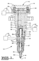
- a hydraulically-actuated fuel injector 10 includes an injector body 11 with a solenoid actuated control valve 12 attached thereto.
- the injector body 11 defines an actuation fluid inlet 13 connected to a source of high pressure actuation fluid 22 via an actuation fluid supply passage 23, and an actuation fluid drain 14 connected to a low pressure return reservoir 20 via a drain passage 21.
- Reservoir 20 is preferably an engine oil sump at atmospheric pressure, and all drains of the injector could be open under the valve cover.
- Injector body 11 also defines a fuel inlet 15 connected to a source of fuel fluid 24 via a fuel supply passage 25.
- injector body 11 includes a nozzle outlet 16 that is preferably appropriately positioned within the combustion space of an internal combustion engine.
- pressurized lubricating oil is used as the hydraulic medium
- distillate diesel fuel is used as the injection medium.
- a hydraulic means to pressurize fuel within fuel injector 10 includes an intensifier piston 35 that reciprocates in a piston bore 36 between a retracted position, as shown, and a downward advanced position.
- Intensifier piston 35 includes an upper or primary hydraulic surface 37 exposed to fluid pressure in a first actuation fluid cavity 34 defined by work passage 31 and a portion of piston bore 36.
- Intensifier piston 35 also includes an opposing hydraulic surface 39 exposed to fluid pressure in a second actuation fluid cavity 38, which is connected to a control passage 32.
- Piston 35 is normally biased toward its retracted position, as shown, by a return spring 40.
- Piston 35 is preferably cylindrically shaped such that hydraulic surfaces 37 and 39 are about equal in area.
- the means for pressurizing fuel also includes a plunger 41 that is positioned in a plunger bore 42.
- Plunger 41 moves with intensifier piston 35 between a retracted position, as shown, and a downward advanced position.
- a portion of plunger bore 42 and plunger 41 define a fuel pressurization chamber 43 that is fluidly connected to nozzle outlet 16 via a nozzle supply passage 45 and a nozzle chamber 46.
- solenoid actuated control valve 12 includes first and second opposing solenoids 18 and 19, respectively.
- Solenoids 18 and 19 are operably coupled to a spool valve member 60, which is capable of moving between a first stop 70 (Fig. 2) and a second stop 71 (Fig. 5).
- the ends of spool valve member 60 are vented to low pressure drain 14 via end drain passages 26 and 27.
- spool valve member 60 preferably defines an internal drain passage 67 that is separate and isolated from an internal high pressure passage 68.
- Spool valve member 60 is preferably hydraulically balanced so that it will stay in one position when neither solenoid 18 nor 19 is energized. Preferably, only one solenoid is energized at any one time.
- spool valve member 60 is positioned in stationary contact with first stop 70 as shown in Fig. 2.
- work passage 31 is connected to actuation fluid drain 14 via drain connection annulus 62, internal drain passage 67 and drain annulus 66.
- control passage 32 is connected to work passage 31 and actuation fluid drain 14 via drain control connection annulus 64 and internal drain passage 67.
- return spring 40 can push intensifier piston 35 upward to displace fluid from work passage 31 into control passage 32 and actuation fluid drain 14. It is also important to note that when spool valve member 60 is in its first position as shown in Fig. 2, high pressure inlet passage 30, which is connected to actuation fluid inlet 13, is blocked.
- solenoid 19 When it is time to initiate an injection event, solenoid 19 is energized, and spool valve member 60 begins moving toward the right in the direction of second stop 71. Over a portion of the distance between stop 70 and 71, spool valve member 60 moves through a first intermediate position (Fig. 3) in which high pressure inlet 30 opens to work passage 31 via inlet annulus 61, internal passage 68 and high pressure connection annulus 63. At the same time, drain annulus 69 opens to control passage 32 so that piston 35 can move downward.
- high pressure inlet 30 When high pressure inlet 30 is connected to work passage 31, high pressure actuation fluid acts on primary hydraulic surface 37 of piston 35, and begins moving it and plunger 41 downward to pressurize fuel in fuel pressurization chamber 43. Fuel pressure quickly rises to a level to open needle valve member 50 and commence the spraying of fuel out of nozzle outlet 16.
- the present invention can be tuned to produce a variety of desirable fuel injection rate traces.
- an engineer has a variety of techniques available with which to control the respective durations of the pilot injection event and the time between the pilot and main injection events.
- the movement rate of spool valve member 60 can be adjusted by an appropriate sizing of solenoid 19.
- the widths and positioning of the various annuluses machined on the outer surface of spool valve member 60 can be adjusted to produce a desired rate shape outcome.
- different injection rate traces can be created by changing the rate at which spool valve member 60 moves between its stops at different engine operating conditions. For instance, a high current in solenoid 19 could cause spool valve member 60 to move rapidly and create one type of injection rate trace, such as a boot shape. And a lower current to solenoid 19 could cause fuel injector 10 to produce a split injection event.
Landscapes
- Engineering & Computer Science (AREA)
- Chemical & Material Sciences (AREA)
- Combustion & Propulsion (AREA)
- Mechanical Engineering (AREA)
- General Engineering & Computer Science (AREA)
- Fuel-Injection Apparatus (AREA)
Description
Claims (14)
- A hydraulically actuated fuel injector (10) comprising:an injector body (11) defining an actuation fluid inlet (13), a first actuation fluid cavity (34), a second actuation fluid cavity (38) and a nozzle outlet (16);a piston (35) positioned in said injector body (11) and being moveable between a retracted position and an advanced position for pressurizing fuel within said fuel injector (10), and said piston (35) having a primary hydraulic surface (37) exposed to fluid in said first actuation fluid cavity (34), and further having an opposing hydraulic surface (39) exposed fluid in said second actuation fluid cavity (38);a control valve (12) that includes a spool valve member (60) moveable a distance between a first position and a second position;said first actuation fluid cavity (34) being closed to said actuation fluid inlet (13) when said spool valve member (60) is in said first position;said first actuation fluid cavity (34) being open, but said second actuation fluid cavity (38) being closed, to said actuation fluid inlet (13) when said spool valve member (60) is moving through a first portion of said distance and applying an actuating fluid force to said primary hydraulic surface to pressurize fuel at said nozzle outlet (16);said first actuation fluid cavity (34) and said second actuation fluid cavity (38) being open to said actuation fluid inlet (13) when said spool valve member (60) is moving through a second portion of said distance and applying a fluid force to the opposing hydraulic surface (39) and changing the fuel pressure at said nozzle outlet (16); andsaid first actuation fluid cavity (34) being open to said actuation fluid inlet (13) when said spool valve member (60) is in said second position.
- The hydraulically actuated fuel injector (10) of claim 1 wherein said control valve (12) includes a pair of opposing solenoids (18,19) operably coupled to said spool valve member (60).
- The hydraulically actuated fuel injector (10) of claim 1 wherein said spool valve member (60) is hydraulically balanced.
- The hydraulically actuated fuel injector (10) of claim 1 wherein said injector body (11) also defines an actuation fluid drain (14);
said first actuation fluid cavity (34) being open to said actuation fluid drain (14) when said spool valve member (60) is in said first position; and
said second actuation fluid cavity (38) being open to said actuation fluid drain (14) when said spool valve member (60) is in said second position. - The hydraulically actuated fuel injector (10) of claim 4 wherein said first actuation fluid cavity (34) and said second actuation fluid cavity (38) are closed to said actuation fluid drain (14) when said spool valve member (60) is moving through said second portion of said distance.
- The hydraulically actuated fuel injector (10) of claim 5 wherein said second actuation fluid cavity (38) is open to said actuation fluid drain (14) when said spool valve member (60) is moving through said first portion of said distance.
- The hydraulically actuated fuel injector (10) of claim 1 wherein said spool valve member (60) defines at least two separate internal passages (67,68).
- The hydraulically actuated fuel injector (10) of claim 7 wherein said spool valve member (60) has an outer surface defining a plurality of annuluses (61-66,69); and
different ones of said plurality of annuluses (61-66,69) are fluidly connected by said separate internal passages (67,68). - A method of injecting fuel comprising the steps of:providing a hydraulically actuated fuel injector (10) with an actuation fluid inlet (13), a spool valve member (60), and a piston (35) being moveable between a retracted position and an advanced position for pressurizing fuel within said fuel injector (10) and having a primary hydraulic surface (37) exposed to fluid in a first actuation fluid cavity (34) and an opposing hydraulic surface (39) exposed fluid in a second actuation fluid cavity (38);moving said spool valve member (60) to a first position in which said first actuation fluid cavity (34) is closed to said actuation fluid inlet (13) ;moving said spool valve member (60) to a second position in which said first actuation fluid cavity (34) is open to said actuation fluid inlet (13) and applying an actuating fluid force to said primary hydraulic surface to pressurize fuel at said nozzle outlet (16) ;moving said spool valve member (60) to a third position in which said first actuation fluid cavity (34) and said second actuation fluid cavity (38) are open to said actuation fluid inlet (13) and applying a fluid force to the opposing hydraulic surface (39) and changing the fuel pressure at said nozzle outlet (16);moving said spool valve member (60) to a fourth position in which said first actuation fluid cavity (34) is open to said actuation fluid inlet (13); andmoving said spool valve member (60) back to said first position.
- The method of claim 9 wherein said fuel injector (10) includes at least one solenoid (18,19) operably coupled to said spool valve member (60); and
said moving steps are accomplished by selectively energizing said at least one solenoid (18,19). - The method of claim 9 wherein said spool valve member (60) moves in a single direction when moving sequentially from said first position to said second position, and then to said third position and then to said fourth position.
- The method of claim 9 wherein said second position and said third position are different portions of a movement distance separating said first position and said fourth position.
- The method of claim 9 wherein said fuel injector (10) includes an actuation fluid drain (14);
said first actuation fluid cavity (34) being open to said actuation fluid drain (14) when said spool valve member (60) is in said first position; and
said second actuation fluid cavity (38) being open to said actuation fluid drain (14) when said spool valve member (60) is in said second position. - The method of claim 13 wherein said first actuation fluid cavity (34) and said second actuation fluid cavity (38) are closed to said actuation fluid drain (14) when said spool valve member (60) is in said third position.
Applications Claiming Priority (3)
| Application Number | Priority Date | Filing Date | Title |
|---|---|---|---|
| US81253 | 1998-05-19 | ||
| US09/081,253 US6053421A (en) | 1998-05-19 | 1998-05-19 | Hydraulically-actuated fuel injector with rate shaping spool control valve |
| PCT/US1999/009385 WO1999060265A1 (en) | 1998-05-19 | 1999-04-30 | Hydraulically-actuated fuel injector with rate shaping spool control valve |
Publications (2)
| Publication Number | Publication Date |
|---|---|
| EP1080306A1 EP1080306A1 (en) | 2001-03-07 |
| EP1080306B1 true EP1080306B1 (en) | 2003-06-25 |
Family
ID=22163036
Family Applications (1)
| Application Number | Title | Priority Date | Filing Date |
|---|---|---|---|
| EP99921548A Expired - Lifetime EP1080306B1 (en) | 1998-05-19 | 1999-04-30 | Hydraulically-actuated fuel injector with rate shaping spool control valve |
Country Status (4)
| Country | Link |
|---|---|
| US (1) | US6053421A (en) |
| EP (1) | EP1080306B1 (en) |
| DE (1) | DE69909082T2 (en) |
| WO (1) | WO1999060265A1 (en) |
Families Citing this family (21)
| Publication number | Priority date | Publication date | Assignee | Title |
|---|---|---|---|---|
| US5970956A (en) * | 1997-02-13 | 1999-10-26 | Sturman; Oded E. | Control module for controlling hydraulically actuated intake/exhaust valves and a fuel injector |
| US6283716B1 (en) * | 1997-10-28 | 2001-09-04 | Coltec Industries Inc. | Multistage blowdown valve for a compressor system |
| US6276610B1 (en) | 1998-12-11 | 2001-08-21 | Diesel Technology Company | Control valve |
| IT1319987B1 (en) * | 2000-03-21 | 2003-11-12 | Fiat Ricerche | COMBUSTION INJECTOR HAVING A CONTROL AREA CONTROLLED BY THE PRESSURE OF THE FUEL IN A CONTROL CHAMBER. |
| US6412473B1 (en) * | 2000-06-29 | 2002-07-02 | Caterpillar Inc. | Rate shaped fluid driven piston assembly and fuel injector using same |
| DE10040526A1 (en) * | 2000-08-18 | 2002-03-14 | Bosch Gmbh Robert | Fuel injection system |
| US6550453B1 (en) | 2000-09-21 | 2003-04-22 | Caterpillar Inc | Hydraulically biased pumping element assembly and fuel injector using same |
| US6568369B1 (en) * | 2000-12-05 | 2003-05-27 | Caterpillar Inc | Common rail injector with separately controlled pilot and main injection |
| US6450778B1 (en) | 2000-12-07 | 2002-09-17 | Diesel Technology Company | Pump system with high pressure restriction |
| US6394070B1 (en) * | 2000-12-19 | 2002-05-28 | Caterpillar Inc. | Dual valve member and fuel injector using same |
| US6848626B2 (en) * | 2001-03-15 | 2005-02-01 | Siemens Vdo Automotive Corporation | End of valve motion detection for a spool control valve |
| US6631853B2 (en) | 2001-04-09 | 2003-10-14 | Siemens Diesel Systems Technologies, Llc | Oil activated fuel injector control valve |
| US6866204B2 (en) * | 2001-04-10 | 2005-03-15 | Siemens Vdo Automotive Corporation | End of valve motion detection for a spool control valve |
| US6830202B2 (en) * | 2002-03-22 | 2004-12-14 | Caterpillar Inc | Two stage intensifier |
| US6830201B2 (en) * | 2002-12-26 | 2004-12-14 | Robert Bosch Gmbh | High pressure control valve for a fuel injector |
| US6982619B2 (en) * | 2003-02-07 | 2006-01-03 | Robert Bosch Gmbh | Solenoid stator assembly having a reinforcement structure |
| JP4075894B2 (en) * | 2004-09-24 | 2008-04-16 | トヨタ自動車株式会社 | Fuel injection device |
| US20060202053A1 (en) * | 2005-03-09 | 2006-09-14 | Gibson Dennis H | Control valve assembly and fuel injector using same |
| KR101063688B1 (en) * | 2008-12-03 | 2011-09-07 | 현대자동차주식회사 | Engine fuel supply and injector therefor |
| US10519916B1 (en) | 2018-06-13 | 2019-12-31 | Caterpillar Inc. | Flexible rate shape common rail fuel system and fuel injector for same |
| US11293392B2 (en) | 2019-02-20 | 2022-04-05 | Ford Global Technologies, Llc | Methods and systems for a fuel injector |
Family Cites Families (17)
| Publication number | Priority date | Publication date | Assignee | Title |
|---|---|---|---|---|
| DE2126736A1 (en) * | 1971-05-28 | 1972-12-07 | Bosch Gmbh Robert | Fuel injection system for internal combustion engines |
| JPS49108427A (en) * | 1973-02-19 | 1974-10-15 | ||
| US3961612A (en) * | 1974-08-22 | 1976-06-08 | Diesel Kiki Kabushiki Kaisha | Fuel injection device for diesel engines |
| JPS51101628A (en) * | 1975-01-24 | 1976-09-08 | Diesel Kiki Co | |
| US4182492A (en) * | 1978-01-16 | 1980-01-08 | Combustion Research & Technology, Inc. | Hydraulically operated pressure amplification system for fuel injectors |
| DE3001166A1 (en) * | 1980-01-15 | 1981-07-23 | Robert Bosch Gmbh, 7000 Stuttgart | FUEL INJECTION SYSTEM |
| JPS57124073A (en) * | 1981-01-24 | 1982-08-02 | Diesel Kiki Co Ltd | Fuel injection device |
| US4640252A (en) * | 1984-01-28 | 1987-02-03 | Mazda Motor Corporation | Fuel injection system for diesel engine |
| JPS61118553A (en) * | 1984-11-14 | 1986-06-05 | Diesel Kiki Co Ltd | Fuel injection valve |
| US4811715A (en) * | 1987-11-02 | 1989-03-14 | Stanadyne, Inc. | Electronic unit injector |
| US5271366A (en) * | 1990-02-07 | 1993-12-21 | Mitsubishi Jidosha K.K. | Fuel injection system |
| US5460329A (en) * | 1994-06-06 | 1995-10-24 | Sturman; Oded E. | High speed fuel injector |
| JP2885076B2 (en) * | 1994-07-08 | 1999-04-19 | 三菱自動車工業株式会社 | Accumulator type fuel injection device |
| US5669355A (en) * | 1994-07-29 | 1997-09-23 | Caterpillar Inc. | Hydraulically-actuated fuel injector with direct control needle valve |
| US5687693A (en) * | 1994-07-29 | 1997-11-18 | Caterpillar Inc. | Hydraulically-actuated fuel injector with direct control needle valve |
| US5697342A (en) * | 1994-07-29 | 1997-12-16 | Caterpillar Inc. | Hydraulically-actuated fuel injector with direct control needle valve |
| US5709341A (en) * | 1996-05-03 | 1998-01-20 | Caterpillar Inc. | Two-stage plunger for rate shaping in a fuel injector |
-
1998
- 1998-05-19 US US09/081,253 patent/US6053421A/en not_active Expired - Fee Related
-
1999
- 1999-04-30 EP EP99921548A patent/EP1080306B1/en not_active Expired - Lifetime
- 1999-04-30 DE DE69909082T patent/DE69909082T2/en not_active Expired - Fee Related
- 1999-04-30 WO PCT/US1999/009385 patent/WO1999060265A1/en not_active Ceased
Also Published As
| Publication number | Publication date |
|---|---|
| DE69909082T2 (en) | 2004-05-06 |
| EP1080306A1 (en) | 2001-03-07 |
| DE69909082D1 (en) | 2003-07-31 |
| US6053421A (en) | 2000-04-25 |
| WO1999060265A1 (en) | 1999-11-25 |
Similar Documents
| Publication | Publication Date | Title |
|---|---|---|
| US6053421A (en) | Hydraulically-actuated fuel injector with rate shaping spool control valve | |
| US5878720A (en) | Hydraulically actuated fuel injector with proportional control | |
| US6119960A (en) | Solenoid actuated valve and fuel injector using same | |
| EP1117927B1 (en) | Hydraulically-actuated fuel injector with intensifier piston always exposed to high pressure actuation fluid inlet | |
| DE69613192T2 (en) | ELECTROMAGNETICALLY ACTUATED MINI AMPLIFIER SHIFT VALVE | |
| US5709341A (en) | Two-stage plunger for rate shaping in a fuel injector | |
| US6283441B1 (en) | Pilot actuator and spool valve assembly | |
| JPH10103185A (en) | Hydraulic operation type fuel injector provided with direct control type needle valve | |
| US6227166B1 (en) | Mechanically-enabled hydraulically-actuated electronically-controlled fuel injection system | |
| US6026785A (en) | Hydraulically-actuated fuel injector with hydraulically assisted closure of needle valve | |
| DE19603435A1 (en) | Nozzle and tip assembly for fuel injector | |
| US6830202B2 (en) | Two stage intensifier | |
| US5713520A (en) | Fast spill device for abruptly ending injection in a hydraulically actuated fuel injector | |
| EP1105640B1 (en) | Valve area scheduling in a double acting piston for a hydraulically-actuated fuel injector | |
| US6161773A (en) | Fuel injector nozzle with guide to check clearance passage providing injection rate shaping | |
| US6655602B2 (en) | Fuel injector having a hydraulically actuated control valve and hydraulic system using same | |
| US6047899A (en) | Hydraulically-actuated fuel injector with abrupt end to injection features | |
| US6378497B1 (en) | Actuation fluid adapter for hydraulically-actuated electronically-controlled fuel injector and engine using same | |
| US6173699B1 (en) | Hydraulically-actuated fuel injector with electronically actuated spill valve | |
| US6935580B2 (en) | Valve assembly having multiple rate shaping capabilities and fuel injector using same | |
| US6454189B1 (en) | Reverse acting nozzle valve and fuel injector using same | |
| US6354270B1 (en) | Hydraulically actuated fuel injector including a pilot operated spool valve assembly and hydraulic system using same | |
| US6595188B2 (en) | Compact valve assembly and fuel injector using same | |
| US6550453B1 (en) | Hydraulically biased pumping element assembly and fuel injector using same | |
| US6425375B1 (en) | Piston and barrel assembly with stepped top and hydraulically-actuated fuel injector utilizing same |
Legal Events
| Date | Code | Title | Description |
|---|---|---|---|
| PUAI | Public reference made under article 153(3) epc to a published international application that has entered the european phase |
Free format text: ORIGINAL CODE: 0009012 |
|
| 17P | Request for examination filed |
Effective date: 20001205 |
|
| AK | Designated contracting states |
Kind code of ref document: A1 Designated state(s): DE FR GB |
|
| 17Q | First examination report despatched |
Effective date: 20010709 |
|
| GRAH | Despatch of communication of intention to grant a patent |
Free format text: ORIGINAL CODE: EPIDOS IGRA |
|
| GRAH | Despatch of communication of intention to grant a patent |
Free format text: ORIGINAL CODE: EPIDOS IGRA |
|
| GRAA | (expected) grant |
Free format text: ORIGINAL CODE: 0009210 |
|
| AK | Designated contracting states |
Designated state(s): DE FR GB |
|
| PG25 | Lapsed in a contracting state [announced via postgrant information from national office to epo] |
Ref country code: FR Free format text: LAPSE BECAUSE OF FAILURE TO SUBMIT A TRANSLATION OF THE DESCRIPTION OR TO PAY THE FEE WITHIN THE PRESCRIBED TIME-LIMIT Effective date: 20030625 |
|
| REG | Reference to a national code |
Ref country code: GB Ref legal event code: FG4D |
|
| REF | Corresponds to: |
Ref document number: 69909082 Country of ref document: DE Date of ref document: 20030731 Kind code of ref document: P |
|
| PG25 | Lapsed in a contracting state [announced via postgrant information from national office to epo] |
Ref country code: GB Free format text: LAPSE BECAUSE OF NON-PAYMENT OF DUE FEES Effective date: 20040430 |
|
| PLBE | No opposition filed within time limit |
Free format text: ORIGINAL CODE: 0009261 |
|
| STAA | Information on the status of an ep patent application or granted ep patent |
Free format text: STATUS: NO OPPOSITION FILED WITHIN TIME LIMIT |
|
| 26N | No opposition filed |
Effective date: 20040326 |
|
| EN | Fr: translation not filed | ||
| GBPC | Gb: european patent ceased through non-payment of renewal fee |
Effective date: 20040430 |
|
| PGFP | Annual fee paid to national office [announced via postgrant information from national office to epo] |
Ref country code: DE Payment date: 20070430 Year of fee payment: 9 |
|
| PG25 | Lapsed in a contracting state [announced via postgrant information from national office to epo] |
Ref country code: DE Free format text: LAPSE BECAUSE OF NON-PAYMENT OF DUE FEES Effective date: 20081101 |