EP1079985B1 - Method and device for cruise control - Google Patents
Method and device for cruise control Download PDFInfo
- Publication number
- EP1079985B1 EP1079985B1 EP99929986A EP99929986A EP1079985B1 EP 1079985 B1 EP1079985 B1 EP 1079985B1 EP 99929986 A EP99929986 A EP 99929986A EP 99929986 A EP99929986 A EP 99929986A EP 1079985 B1 EP1079985 B1 EP 1079985B1
- Authority
- EP
- European Patent Office
- Prior art keywords
- vehicle
- engine
- value
- control unit
- speed
- Prior art date
- Legal status (The legal status is an assumption and is not a legal conclusion. Google has not performed a legal analysis and makes no representation as to the accuracy of the status listed.)
- Expired - Lifetime
Links
Images

Classifications
-
- B—PERFORMING OPERATIONS; TRANSPORTING
- B60—VEHICLES IN GENERAL
- B60K—ARRANGEMENT OR MOUNTING OF PROPULSION UNITS OR OF TRANSMISSIONS IN VEHICLES; ARRANGEMENT OR MOUNTING OF PLURAL DIVERSE PRIME-MOVERS IN VEHICLES; AUXILIARY DRIVES FOR VEHICLES; INSTRUMENTATION OR DASHBOARDS FOR VEHICLES; ARRANGEMENTS IN CONNECTION WITH COOLING, AIR INTAKE, GAS EXHAUST OR FUEL SUPPLY OF PROPULSION UNITS IN VEHICLES
- B60K31/00—Vehicle fittings, acting on a single sub-unit only, for automatically controlling vehicle speed, i.e. preventing speed from exceeding an arbitrarily established velocity or maintaining speed at a particular velocity, as selected by the vehicle operator
- B60K31/02—Vehicle fittings, acting on a single sub-unit only, for automatically controlling vehicle speed, i.e. preventing speed from exceeding an arbitrarily established velocity or maintaining speed at a particular velocity, as selected by the vehicle operator including electrically actuated servomechanism
- B60K31/04—Vehicle fittings, acting on a single sub-unit only, for automatically controlling vehicle speed, i.e. preventing speed from exceeding an arbitrarily established velocity or maintaining speed at a particular velocity, as selected by the vehicle operator including electrically actuated servomechanism and means for comparing one electrical quantity, e.g. voltage, pulse, waveform, flux, or the like, with another quantity of a like kind, which comparison means is involved in the development of an electrical signal which is fed into the controlling means
- B60K31/042—Vehicle fittings, acting on a single sub-unit only, for automatically controlling vehicle speed, i.e. preventing speed from exceeding an arbitrarily established velocity or maintaining speed at a particular velocity, as selected by the vehicle operator including electrically actuated servomechanism and means for comparing one electrical quantity, e.g. voltage, pulse, waveform, flux, or the like, with another quantity of a like kind, which comparison means is involved in the development of an electrical signal which is fed into the controlling means where at least one electrical quantity is set by the vehicle operator
- B60K31/045—Vehicle fittings, acting on a single sub-unit only, for automatically controlling vehicle speed, i.e. preventing speed from exceeding an arbitrarily established velocity or maintaining speed at a particular velocity, as selected by the vehicle operator including electrically actuated servomechanism and means for comparing one electrical quantity, e.g. voltage, pulse, waveform, flux, or the like, with another quantity of a like kind, which comparison means is involved in the development of an electrical signal which is fed into the controlling means where at least one electrical quantity is set by the vehicle operator in a memory, e.g. a capacitor
- B60K31/047—Vehicle fittings, acting on a single sub-unit only, for automatically controlling vehicle speed, i.e. preventing speed from exceeding an arbitrarily established velocity or maintaining speed at a particular velocity, as selected by the vehicle operator including electrically actuated servomechanism and means for comparing one electrical quantity, e.g. voltage, pulse, waveform, flux, or the like, with another quantity of a like kind, which comparison means is involved in the development of an electrical signal which is fed into the controlling means where at least one electrical quantity is set by the vehicle operator in a memory, e.g. a capacitor the memory being digital
-
- F—MECHANICAL ENGINEERING; LIGHTING; HEATING; WEAPONS; BLASTING
- F02—COMBUSTION ENGINES; HOT-GAS OR COMBUSTION-PRODUCT ENGINE PLANTS
- F02D—CONTROLLING COMBUSTION ENGINES
- F02D31/00—Use of speed-sensing governors to control combustion engines, not otherwise provided for
- F02D31/001—Electric control of rotation speed
- F02D31/002—Electric control of rotation speed controlling air supply
-
- F—MECHANICAL ENGINEERING; LIGHTING; HEATING; WEAPONS; BLASTING
- F02—COMBUSTION ENGINES; HOT-GAS OR COMBUSTION-PRODUCT ENGINE PLANTS
- F02D—CONTROLLING COMBUSTION ENGINES
- F02D31/00—Use of speed-sensing governors to control combustion engines, not otherwise provided for
- F02D31/001—Electric control of rotation speed
- F02D31/007—Electric control of rotation speed controlling fuel supply
-
- B—PERFORMING OPERATIONS; TRANSPORTING
- B60—VEHICLES IN GENERAL
- B60W—CONJOINT CONTROL OF VEHICLE SUB-UNITS OF DIFFERENT TYPE OR DIFFERENT FUNCTION; CONTROL SYSTEMS SPECIALLY ADAPTED FOR HYBRID VEHICLES; ROAD VEHICLE DRIVE CONTROL SYSTEMS FOR PURPOSES NOT RELATED TO THE CONTROL OF A PARTICULAR SUB-UNIT
- B60W50/00—Details of control systems for road vehicle drive control not related to the control of a particular sub-unit, e.g. process diagnostic or vehicle driver interfaces
- B60W2050/0001—Details of the control system
- B60W2050/0002—Automatic control, details of type of controller or control system architecture
- B60W2050/0008—Feedback, closed loop systems or details of feedback error signal
- B60W2050/001—Proportional integral [PI] controller
-
- B—PERFORMING OPERATIONS; TRANSPORTING
- B60—VEHICLES IN GENERAL
- B60W—CONJOINT CONTROL OF VEHICLE SUB-UNITS OF DIFFERENT TYPE OR DIFFERENT FUNCTION; CONTROL SYSTEMS SPECIALLY ADAPTED FOR HYBRID VEHICLES; ROAD VEHICLE DRIVE CONTROL SYSTEMS FOR PURPOSES NOT RELATED TO THE CONTROL OF A PARTICULAR SUB-UNIT
- B60W2510/00—Input parameters relating to a particular sub-units
- B60W2510/06—Combustion engines, Gas turbines
- B60W2510/0638—Engine speed
-
- B—PERFORMING OPERATIONS; TRANSPORTING
- B60—VEHICLES IN GENERAL
- B60W—CONJOINT CONTROL OF VEHICLE SUB-UNITS OF DIFFERENT TYPE OR DIFFERENT FUNCTION; CONTROL SYSTEMS SPECIALLY ADAPTED FOR HYBRID VEHICLES; ROAD VEHICLE DRIVE CONTROL SYSTEMS FOR PURPOSES NOT RELATED TO THE CONTROL OF A PARTICULAR SUB-UNIT
- B60W2710/00—Output or target parameters relating to a particular sub-units
- B60W2710/06—Combustion engines, Gas turbines
- B60W2710/0605—Throttle position
Definitions
- the present invention relates to a method for cruise control according to the preamble of the appended claim 1.
- the invention is especially intended for use with passenger cars of the kind equipped with cruise control.
- the invention also relates to a device for cruise control according to the preamble of the appended claim 5.
- constant speed control devices for automatic control of the vehicle speed in relation to a pre-set target value.
- a cruise control would normally be included as a function of a computerised control unit in the vehicle in question.
- a setting device by which the driver can set a target value corresponding to the desired vehicle speed, would be connected to the control unit.
- the control unit is adapted to control the operation of the vehicle engine, in dependence of the currently set target value, in such a manner that the vehicle will reach the speed corresponding to the target value. This control is performed in dependence of various operating parameters of the vehicle, such as, for example, the current engine load.
- the control towards the set target value is normally performed by comparison of a signal corresponding to the target value with an actual value, i.e. a current value of vehicle speed, whereby the latter value can be determined by an existing speedometer in the vehicle.
- the vehicle fuelling throttle can be set to a certain angular position. This angular position in turn corresponds to a certain amount of air supplied to, and thus to a certain output torque from, the engine. In this manner, the desired target value regarding vehicle speed can be reached.
- the throttle can be controlled mechanically, or may alternatively consist of an electrically controlled throttle (also called an "E throttle"). In the latter case, the throttle angle is adjusted by means of a servomotor connected to the control unit and coupled to the throttle.
- the cruise control may be performed by means of a control method utilising a so-called P controller, i. e. based on proportional control.
- P controller i. e. based on proportional control.
- This type of control multiplies, in the control unit, the difference between the present actual value and the target value by a predetermined gain factor. This provides an output value that is subsequently used by the control unit for adjusting the throttle.
- the P control method discussed above may advantageously be complemented by an integrating factor, i.e. so as to obtain a PI controller.
- an output value is calculated, in the control unit, which consists of the sum of a proportional portion (a "P portion") and an integrated portion (an "I portion”), where the latter portion is based on an integration of the difference between the vehicle velocity and the target value, over time. This total output value is then utilised for adjusting the throttle angle to a desired value.
- a driving situation may sometimes occur demanding a torque increase from the engine, which in turn corresponds to a demand for an increased airflow to the engine.
- a situation might for example occur if the vehicle, after being driven on level ground with a moderate load and at constant speed, reaches a steep uphill slope.
- the proportional portion as well as the integrated portion will increase successively at this stage, as the current actual value will fall below the target value when the vehicle reaches such an uphill slope.
- An increase of the proportional and the integrated portions will of course also lead to an increase of the sum of these two control factors.
- an increase of this sum corresponds to an increase of the throttle angle.
- This entails a successive opening of the throttle until the vehicle speed reaches the set target value again.
- the set throttle angle and the amount of air supplied, which entails that after having increased the throttle angle up to a certain value (for example in connection with the situation described above), any further increase of this angle will not provide any further substantial increase in the amount of air fed into the engine.
- a certain value for example in connection with the situation described above
- an increased angle will not provide any substantial increase of the engine torque.
- the above relationship entails, that when the integrated portion (and consequently also the throttle angle) decreases from a state of very large throttle angle, initially there will not be any substantial decrease in the amount of air and thus neither any substantial decrease of the engine torque.
- the above situation may then lead to the following problem: If the vehicle, after being driven at a high torque, reaches a condition requiring a relatively low torque, which could be said to correspond to the vehicle, after being driven uphill, reaching the crest of the hill, then the throttle angle would be relatively large. At this stage, there would also be a high output torque from the engine, causing the vehicle to accelerate. This is registered by the control unit, as the actual value then exceeds the target value, and will in turn lead to a decrease of the integrated portion as well as the proportional portion of the value calculated by the PI controller. This will also cause the throttle angle to decrease.
- this decrease will, however, entail only a very slow decrease of the supplied amount of air (and thus torque), as the integrated portion was previously allowed to rise to a very high value.
- the engine output torque will thus be generally constant for a relatively long period of time, while the integrated portion decreases. This entails that the vehicle will accelerate after having reached the crest of the hill, which is of course a disadvantage.
- the above problem can be solved in part by arranging the control unit so as to limit the integrated portion to a maximum allowed value.
- a method according to the preamble of independent claim 1 and a device according to the preamble of independent claim 5 is known from US-A-5 479 349.
- the object of the present invention is to provide an improved method for cruise control, by which the problem described above regarding unwanted acceleration, is solved.
- This object is achieved by a method, the characteristics of which are disclosed in the appended claim 1.
- the object is also achieved by means of a device, the characteristics of which are disclosed in the appended claim 5.
- the method according to the invention is intended for cruise control of an automotive vehicle and includes determination of a target value stating a desired speed of the vehicle, determination of an actual value stating the current speed of the vehicle, repeated calculation of an integrated control factor in dependence of the current difference between said actual value and said target value, and generation of an output signal from a control unit in dependence of the size of said control factor, said output signal being utilised for controlling the vehicle engine to a corresponding output torque.
- the invention is characterised by including a limitation of said integrated factor to a maximum value, preselected in dependence of the current rotational speed of said engine.
- the invention is utilised in such a way that said output signal is utilised for adjusting a corresponding angle of an engine fuelling throttle.
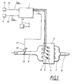
- Fig. 1 schematically illustrates an arrangement in which the present invention can be utilised.
- the arrangement is intended for an automotive vehicle, e.g. a passenger car, and comprises a central control unit 1, which is preferably computer based and consists of an existing computer unit in the vehicle for controlling various vehicle functions, e.g. for controlling the fuel supply to a combustion engine 2.
- the engine 2 is a conventional petrol engine.
- the engine 2 shown in a simplified form in Fig. 1, is in the known manner supplied with inflowing air via an air inlet 3.
- the engine 2 is further equipped with a number of cylinders 4 and a corresponding number of injection devices 5 for supplying fuel.
- Each fuel injection device 5 is connected to the control unit 1 by means of an electrical connection 6.
- the control unit 1 is functioning in a known manner to control the fuel supply to each injection device 5 with fuel from a (not shown) fuel tank, such that in each instant a suitable air/fuel mixture will be supplied to the engine 2 and consumed therein.
- the control of the engine 2 is performed in dependence of various parameters indicating the operating conditions of the engine 2 and of the vehicle in question.
- the engine control may be performed in dependence of current throttle actuation, engine speed, the amount of air injected into the engine, and the oxygen concentration of the exhaust gases. This type of engine control is as such known and will not be described in detail here.
- the exhaust gases from the engine 2 are lead from each cylinder 4 by means of a manifold 7 and on to an exhaust pipe 8 connected to the manifold 7. Further downstream along the exhaust pipe 8 there may also be other (not shown) components provided, for example an exhaust gas catalytic converter, a lambda sonde and a silencer.
- the control unit 1 is functioning to provide cruise control for the vehicle in question.
- This cruise control is a function as such previously known and, according to the embodiment, it is based on that the vehicle driver, with the aid of an operating device 9, is allowed to enter a value corresponding to a speed v tar with which the vehicle should be driven.
- This operating device 9 consists of a control switch, preferably located close to the vehicle steering wheel or dashboard (not shown) and connected to the control unit 1 via an electrical connection 10.
- a speedometer 11 is further connected to the control unit 1 via another connection 12, providing the control unit 1 with a signal indicating the actual speed v act of the vehicle. Besides this, there is a speed sensor 13 connected to the control unit 1 via a further connection 14, providing the control unit 1 with a signal indicating the current rotational speed n of the engine 2.
- the control unit 1 is arranged for cruise control by means of so-called PI control, which as such is a known control method by which an output value S is calculated at regular intervals.
- This value S is calculated as the sum of a proportional portion P p and an integrated portion I p .
- this total value S creates an output signal from the control unit 1 that is used for adjustment of a fuelling throttle 15 provided at the air inlet 3 of the engine 2.
- the throttle 15 is preferably operated electrically and is to this end provided with a controllable servomotor 16, with the aid of which the throttle 15 may be set to a certain, desired angular position ⁇ , for feeding a suitable amount of air to the engine 2 in dependence of the current operating conditions.
- the servomotor 16 is thus connected to the control unit 1 via another connection 17.
- the system also comprises a position sensor (not shown) for sensing the position of the vehicle throttle pedal.
- the control unit 1 is functioning, at periodically reoccurring occasions, to calculate the proportional portion P p as well as the integrated portion I p .
- a current value of the integrated portion l p (n) is calculated through a repeated calculation based on a previous value of the integrated portion l p (n-1) , to which is added an increment proportional to the difference between the current actual value v act and the set target value v tar , i.e.
- I p (n) I p (n-1) + I gain (v tar - v act ) where I gain is a predetermined gain factor.
- the current value of the integrated portion I p (n) is calculated at predetermined, periodical intervals, preferably being of the order of one or two milliseconds.
- FIG. 2 shows a diagram illustrating the relationship between the set throttle angle ⁇ and the amount of air Q fed to the engine 2.
- a certain amount of air in turn corresponds to a certain output torque from the engine.
- the diagram shows three different curves, corresponding to three different speeds, n 1 , n 2 and n 3 , respectively, of the engine 2, whereby n 2 > n 1 , n 3 > n 1 and n 3 > n 2 .
- the integrated portion I p (n) is limited to a speed-dependent maximum value, i. e. a maximum value being predetermined for each engine speed (alternatively speed range). In the discussed example this corresponds to the integrated portion I p (n) not being allowed, during the control sequence, to rise higher than a maximum value, corresponding to the throttle angle being so large that any further increase thereof would not provide any further substantial increase of the air amount Q.
- This maximum value may be said to correspond to point C in Fig. 2.
- the integrated portion would have continued to increase to a very high value during the above-described phase when the vehicle is striving to achieve the target value v tar . This would lead to the problem described by way of introduction, where the integrated portion would then reach a value corresponding to a large throttle angle (i.e. a point on the far right of each curve according to Fig. 2).
- a limit is determined for the value that the integrated portion is allowed to reach during operation at a certain rotational speed.
- the control unit 1 is, in advance, provided with stored information that, for a number of different speeds or speed ranges, states a corresponding number of maximum values for the integrated portion. In this way, a certain maximum value is connected to a certain corresponding rotational speed or speed range.
- the maximum values allowed for the integrated portion are selected for each speed n 1 , n 2 , n 3 , so as to correspond to certain throttle angles. Furthermore, these maximum values are selected so as not to be located in areas where any further increase of the throttle angle would not yield any substantial further increase of the air amount to the engine. Besides the above-mentioned point C, corresponding to a first speed n 1 , these maximum values correspond on the one hand to the point C', valid for a second speed n 2 , and on the other to the point C", valid for a third speed n 3 . As the integrated portion is not allowed to rise above what corresponds to these points C, C', C", a decrease of the throttle angle ⁇ is achieved when the integrated portion is reduced, and a substantial corresponding decrease in the air amount Q is achieved when this is necessary.
- the above driving situation with an increased torque will entail that the integrated portion is not allowed to rise above its maximum, speed-dependent value.
- a lower torque which e.g. corresponds to the vehicle reaching the crest of an uphill slope, a certain throttle angle and a corresponding air amount will be present.
- a high output torque from the engine will then prevail, causing the vehicle to start accelerating.
- This speed increase is sensed by the control unit and will cause a decrease of the integrated portion.
- a decrease of the throttle angle will be achieved very rapidly, so that a rapid decrease of the air amount (and thereby the engine torque) is also achieved.
- the speed n 1 this can be described as going from point C to point B. In this way, the problem occurring with the known art, signifying the creation of a long acceleration after reaching the crest of the uphill slope, is eliminated.
- the values corresponding to the maximum values for the integrated portion are preferably stored as a table in a memory in the control unit 1. Depending on the currently prevailing rotational speed, the control unit 1 can use a relevant maximum value for the integrated portion.
- the invention is not limited to the embodiment described above, but may be varied within the scope of the appended patent claims.
- the number of cylinders, the type of fuel injection etc. of the engine may vary.
- the fuelling throttle may be controlled electrically as well as mechanically.
- this value can be determined indirectly, based upon a measurement of the speed n in combination with a signal indicating the presently used gear ratio.
- One alternative method for indirectly providing a representation of the vehicle speed is to use, if available, a signal from an ABS type brake system, which would then be available via an electrical connection. Also a representation of the engine speed can be determined indirectly, without using a speed sensor.
- the invention can also be used in those cases where the control unit is provided with information about a maximum allowed vehicle velocity.
- the gain factors P gain and I gain may be constant or may alternatively be variable and be determined depending on e.g. vehicle speed.
Landscapes
- Engineering & Computer Science (AREA)
- Chemical & Material Sciences (AREA)
- Combustion & Propulsion (AREA)
- Mechanical Engineering (AREA)
- General Engineering & Computer Science (AREA)
- Transportation (AREA)
- Controls For Constant Speed Travelling (AREA)
- Control Of Vehicle Engines Or Engines For Specific Uses (AREA)
- Electrical Control Of Air Or Fuel Supplied To Internal-Combustion Engine (AREA)
Description
- The present invention relates to a method for cruise control according to the preamble of the appended claim 1. The invention is especially intended for use with passenger cars of the kind equipped with cruise control. The invention also relates to a device for cruise control according to the preamble of the appended
claim 5. - In connection with automotive vehicles, especially passenger cars, constant speed control devices (also called cruise control devices) for automatic control of the vehicle speed in relation to a pre-set target value. According to the known art, such a cruise control would normally be included as a function of a computerised control unit in the vehicle in question. A setting device, by which the driver can set a target value corresponding to the desired vehicle speed, would be connected to the control unit. The control unit is adapted to control the operation of the vehicle engine, in dependence of the currently set target value, in such a manner that the vehicle will reach the speed corresponding to the target value. This control is performed in dependence of various operating parameters of the vehicle, such as, for example, the current engine load.
- The control towards the set target value is normally performed by comparison of a signal corresponding to the target value with an actual value, i.e. a current value of vehicle speed, whereby the latter value can be determined by an existing speedometer in the vehicle. Depending on the difference existing between the actual value and the target value at the time of measurement, the vehicle fuelling throttle can be set to a certain angular position. This angular position in turn corresponds to a certain amount of air supplied to, and thus to a certain output torque from, the engine. In this manner, the desired target value regarding vehicle speed can be reached. In a manner as such previously known, the throttle can be controlled mechanically, or may alternatively consist of an electrically controlled throttle (also called an "E throttle"). In the latter case, the throttle angle is adjusted by means of a servomotor connected to the control unit and coupled to the throttle.
- According to the known art, the cruise control may be performed by means of a control method utilising a so-called P controller, i. e. based on proportional control. This type of control multiplies, in the control unit, the difference between the present actual value and the target value by a predetermined gain factor. This provides an output value that is subsequently used by the control unit for adjusting the throttle.
- The P control method discussed above may advantageously be complemented by an integrating factor, i.e. so as to obtain a PI controller. Hereby, an output value is calculated, in the control unit, which consists of the sum of a proportional portion (a "P portion") and an integrated portion (an "I portion"), where the latter portion is based on an integration of the difference between the vehicle velocity and the target value, over time. This total output value is then utilised for adjusting the throttle angle to a desired value.
- When a cruise control is used in a vehicle, a driving situation may sometimes occur demanding a torque increase from the engine, which in turn corresponds to a demand for an increased airflow to the engine. Such a situation might for example occur if the vehicle, after being driven on level ground with a moderate load and at constant speed, reaches a steep uphill slope. With a cruise control based on previously known PI regulators, in such a situation, the proportional portion as well as the integrated portion will increase successively at this stage, as the current actual value will fall below the target value when the vehicle reaches such an uphill slope. An increase of the proportional and the integrated portions will of course also lead to an increase of the sum of these two control factors. According to the known technique, an increase of this sum corresponds to an increase of the throttle angle. This entails a successive opening of the throttle until the vehicle speed reaches the set target value again. In this context, however, it should be noted that in today's vehicles there is normally a relationship between the set throttle angle and the amount of air supplied, which entails that after having increased the throttle angle up to a certain value (for example in connection with the situation described above), any further increase of this angle will not provide any further substantial increase in the amount of air fed into the engine. This also means that an increased angle will not provide any substantial increase of the engine torque. Vice versa, the above relationship entails, that when the integrated portion (and consequently also the throttle angle) decreases from a state of very large throttle angle, initially there will not be any substantial decrease in the amount of air and thus neither any substantial decrease of the engine torque.
- The above situation may then lead to the following problem: If the vehicle, after being driven at a high torque, reaches a condition requiring a relatively low torque, which could be said to correspond to the vehicle, after being driven uphill, reaching the crest of the hill, then the throttle angle would be relatively large. At this stage, there would also be a high output torque from the engine, causing the vehicle to accelerate. This is registered by the control unit, as the actual value then exceeds the target value, and will in turn lead to a decrease of the integrated portion as well as the proportional portion of the value calculated by the PI controller. This will also cause the throttle angle to decrease. According to what was explained above, this decrease will, however, entail only a very slow decrease of the supplied amount of air (and thus torque), as the integrated portion was previously allowed to rise to a very high value. As a consequence of the relationship existing between the set throttle angle and the amount of air fed to the engine, the engine output torque will thus be generally constant for a relatively long period of time, while the integrated portion decreases. This entails that the vehicle will accelerate after having reached the crest of the hill, which is of course a disadvantage.
- According to the known technique, the above problem can be solved in part by arranging the control unit so as to limit the integrated portion to a maximum allowed value.
- A method according to the preamble of independent claim 1 and a device according to the preamble of
independent claim 5 is known from US-A-5 479 349. - The object of the present invention is to provide an improved method for cruise control, by which the problem described above regarding unwanted acceleration, is solved. This object is achieved by a method, the characteristics of which are disclosed in the appended claim 1. The object is also achieved by means of a device, the characteristics of which are disclosed in the appended
claim 5. - The method according to the invention is intended for cruise control of an automotive vehicle and includes determination of a target value stating a desired speed of the vehicle, determination of an actual value stating the current speed of the vehicle, repeated calculation of an integrated control factor in dependence of the current difference between said actual value and said target value, and generation of an output signal from a control unit in dependence of the size of said control factor, said output signal being utilised for controlling the vehicle engine to a corresponding output torque. The invention is characterised by including a limitation of said integrated factor to a maximum value, preselected in dependence of the current rotational speed of said engine.
- Preferably, the invention is utilised in such a way that said output signal is utilised for adjusting a corresponding angle of an engine fuelling throttle. By making the maximum value of the integrated factor speed dependent, a substantial advantage is achieved by always obtaining a quick and efficient engine torque decrease during any decrease in the throttle angle.
- Advantageous embodiments of the invention are disclosed in the subsequent, dependent claims.
- The present invention will be explained further below, with reference to a preferred embodiment and to the enclosed drawings, in which:
- Fig. 1
- schematically illustrates an arrangement in which the present invention can be utilised, and
- Fig. 2
- is a diagram including a multitude of curves defining the relationship between the amount of air supplied and the throttle angle setting, for a combustion engine utilising the invention.
- Fig. 1 schematically illustrates an arrangement in which the present invention can be utilised. According to a preferred embodiment, the arrangement is intended for an automotive vehicle, e.g. a passenger car, and comprises a central control unit 1, which is preferably computer based and consists of an existing computer unit in the vehicle for controlling various vehicle functions, e.g. for controlling the fuel supply to a
combustion engine 2. According to the embodiment, theengine 2 is a conventional petrol engine. - The
engine 2, shown in a simplified form in Fig. 1, is in the known manner supplied with inflowing air via anair inlet 3. Theengine 2 is further equipped with a number ofcylinders 4 and a corresponding number ofinjection devices 5 for supplying fuel. Eachfuel injection device 5 is connected to the control unit 1 by means of anelectrical connection 6. - The control unit 1 is functioning in a known manner to control the fuel supply to each
injection device 5 with fuel from a (not shown) fuel tank, such that in each instant a suitable air/fuel mixture will be supplied to theengine 2 and consumed therein. The control of theengine 2 is performed in dependence of various parameters indicating the operating conditions of theengine 2 and of the vehicle in question. For example, the engine control may be performed in dependence of current throttle actuation, engine speed, the amount of air injected into the engine, and the oxygen concentration of the exhaust gases. This type of engine control is as such known and will not be described in detail here. - The exhaust gases from the
engine 2 are lead from eachcylinder 4 by means of amanifold 7 and on to anexhaust pipe 8 connected to themanifold 7. Further downstream along theexhaust pipe 8 there may also be other (not shown) components provided, for example an exhaust gas catalytic converter, a lambda sonde and a silencer. - The control unit 1 is functioning to provide cruise control for the vehicle in question. This cruise control is a function as such previously known and, according to the embodiment, it is based on that the vehicle driver, with the aid of an
operating device 9, is allowed to enter a value corresponding to a speed vtar with which the vehicle should be driven. Thisoperating device 9 consists of a control switch, preferably located close to the vehicle steering wheel or dashboard (not shown) and connected to the control unit 1 via anelectrical connection 10. - A speedometer 11 is further connected to the control unit 1 via another
connection 12, providing the control unit 1 with a signal indicating the actual speed vact of the vehicle. Besides this, there is aspeed sensor 13 connected to the control unit 1 via afurther connection 14, providing the control unit 1 with a signal indicating the current rotational speed n of theengine 2. - According to the embodiment, the control unit 1 is arranged for cruise control by means of so-called PI control, which as such is a known control method by which an output value S is calculated at regular intervals. This value S is calculated as the sum of a proportional portion Pp and an integrated portion Ip. In accordance with what will be described more closely below, this total value S creates an output signal from the control unit 1 that is used for adjustment of a fuelling
throttle 15 provided at theair inlet 3 of theengine 2. Thethrottle 15 is preferably operated electrically and is to this end provided with acontrollable servomotor 16, with the aid of which thethrottle 15 may be set to a certain, desired angular position α, for feeding a suitable amount of air to theengine 2 in dependence of the current operating conditions. Theservomotor 16 is thus connected to the control unit 1 via anotherconnection 17. For controlling thethrottle 15, the system also comprises a position sensor (not shown) for sensing the position of the vehicle throttle pedal. - The control unit 1 is functioning, at periodically reoccurring occasions, to calculate the proportional portion Pp as well as the integrated portion Ip. The proportional portion Pp is, on every calculation occasion, proportional to the difference between the current actual value vact and the set target value vtar, i.e.
throttle 15 to a corresponding angle α. This signal is output from the control unit 1 to theservomotor 16 of the throttle 15 (see Fig. 1). - The function of the invention will now be described more closely, with reference to Fig. 2. This figure shows a diagram illustrating the relationship between the set throttle angle α and the amount of air Q fed to the
engine 2. A certain amount of air in turn corresponds to a certain output torque from the engine. The diagram shows three different curves, corresponding to three different speeds, n1, n2 and n3, respectively, of theengine 2, whereby n2 > n1, n3 > n1 and n3 > n2. - From the diagram can be gathered that, for a given engine speed n there is a predefined relationship between the throttle angle α and the amount of air Q. From the diagram it can further bee seen that the higher the engine speed n, the larger the difference in air amount Q between an operating condition with relatively small throttle angle α, and an operating condition with relatively large throttle angle α. The latter operating condition is then characterised in that a further increase of the throttle angle α will not provide any substantial further addition of air amount Q.
- When the vehicle in question is in a condition where cruise control has been initiated, the control unit 1 will thus, in periodically recurrent steps (n, n+1, n+2, ...) calculate the output value S according to what has been described above. During continuous driving of the vehicle at a certain rotational speed n1 and a set desired speed vtar, the control unit 1 will adjust the throttle angle α to such a value that this desired speed vtar is achieved. This condition corresponds to what is designated as point A in Fig. 2. Thus, the actual speed of the vehicle in this condition is equal to the set target value, i.e. vact = vtar.
- When the vehicle arrives into a driving situation requiring a higher torque from the engine, for example when the vehicle reaches a steep uphill slope with a maintained set target value vtar, the vehicle speed will initially be somewhat reduced. This entails that the proportional portion Pp as well as the integrated portion Ip starts to increase, thereby contributing to an increased total S. This leads to an increased throttle angle α, corresponding to an increased amount of air Q being fed to the engine. In this way a necessary torque increase is provided, allowing the set target value vtar to be reached again. This condition corresponds to what is designated as point B in Fig. 2.
- The longer time it takes for the vehicle to reach the target value vtar, the further up the curve for the current rotational speed n1 the point B will be located. For this reason, and against the background of the relationship between the throttle angle α and the air amount Q, it is a basic principle behind the present invention, that the integrated portion Ip (n) is limited to a speed-dependent maximum value, i. e. a maximum value being predetermined for each engine speed (alternatively speed range). In the discussed example this corresponds to the integrated portion Ip (n) not being allowed, during the control sequence, to rise higher than a maximum value, corresponding to the throttle angle being so large that any further increase thereof would not provide any further substantial increase of the air amount Q. This maximum value may be said to correspond to point C in Fig. 2.
- As the proportional portion Pp does not increase to more than a value corresponding to the difference between the set target value vtar and the current actual speed vact, (compare above), this portion will be negligible in case the integrated portion Ip has increased to a very high value. According to the invention, there is thus, in principle, no need for limitation of the proportional portion Pp.
- If this maximum value had not been chosen and used according to the invention (i.e. if the cruise control had been controlled according to the previously known art) the integrated portion would have continued to increase to a very high value during the above-described phase when the vehicle is striving to achieve the target value vtar. This would lead to the problem described by way of introduction, where the integrated portion would then reach a value corresponding to a large throttle angle (i.e. a point on the far right of each curve according to Fig. 2). When the vehicle subsequently reaches a condition requiring only a low torque, an acceleration would occur, as the integrated portion would then have to drop during a relatively long period of time (corresponding to a decrease of throttle angle during a long period of time) before any substantial decrease of the air amount, and consequently of the torque, would be obtained.
- According to the present invention, a limit is determined for the value that the integrated portion is allowed to reach during operation at a certain rotational speed. To this end, the control unit 1 is, in advance, provided with stored information that, for a number of different speeds or speed ranges, states a corresponding number of maximum values for the integrated portion. In this way, a certain maximum value is connected to a certain corresponding rotational speed or speed range.
- With reference to Fig. 2, it can be gathered that the maximum values allowed for the integrated portion are selected for each speed n1, n2, n3, so as to correspond to certain throttle angles. Furthermore, these maximum values are selected so as not to be located in areas where any further increase of the throttle angle would not yield any substantial further increase of the air amount to the engine. Besides the above-mentioned point C, corresponding to a first speed n1, these maximum values correspond on the one hand to the point C', valid for a second speed n2, and on the other to the point C", valid for a third speed n3. As the integrated portion is not allowed to rise above what corresponds to these points C, C', C", a decrease of the throttle angle α is achieved when the integrated portion is reduced, and a substantial corresponding decrease in the air amount Q is achieved when this is necessary.
- With the method according to the invention, the above driving situation with an increased torque will entail that the integrated portion is not allowed to rise above its maximum, speed-dependent value. When a lower torque is subsequently required, which e.g. corresponds to the vehicle reaching the crest of an uphill slope, a certain throttle angle and a corresponding air amount will be present. A high output torque from the engine will then prevail, causing the vehicle to start accelerating. This speed increase is sensed by the control unit and will cause a decrease of the integrated portion. As the integrated portion during the previous procedure was limited to its maximum value, a decrease of the throttle angle will be achieved very rapidly, so that a rapid decrease of the air amount (and thereby the engine torque) is also achieved. For the speed n1, this can be described as going from point C to point B. In this way, the problem occurring with the known art, signifying the creation of a long acceleration after reaching the crest of the uphill slope, is eliminated.
- The values corresponding to the maximum values for the integrated portion are preferably stored as a table in a memory in the control unit 1. Depending on the currently prevailing rotational speed, the control unit 1 can use a relevant maximum value for the integrated portion.
- The invention is not limited to the embodiment described above, but may be varied within the scope of the appended patent claims. For example, the number of cylinders, the type of fuel injection etc. of the engine may vary. Furthermore, the fuelling throttle may be controlled electrically as well as mechanically.
- As an alternative to using a speedometer for producing an indication of the current vehicle speed vact, this value can be determined indirectly, based upon a measurement of the speed n in combination with a signal indicating the presently used gear ratio. One alternative method for indirectly providing a representation of the vehicle speed is to use, if available, a signal from an ABS type brake system, which would then be available via an electrical connection. Also a representation of the engine speed can be determined indirectly, without using a speed sensor.
- Besides those applications where a driver sets a desired target value himself, the invention can also be used in those cases where the control unit is provided with information about a maximum allowed vehicle velocity.
- The gain factors Pgain and Igain, respectively, mentioned above may be constant or may alternatively be variable and be determined depending on e.g. vehicle speed.
- Finally applies that the invention can be utilised also for other types of regulator, for example a PID regulator.
Claims (6)
- A method for cruise control of an automotive vehicle, including:determination of a target value (vtar) stating a desired velocity of the vehicle,determination of an actual value (vact) stating the current speed of the vehicle,repeated calculation of an integrated control factor (lp (n)) in dependence of the current difference between said actual value (vact) and said target value (vtar), andgeneration of an output signal (α) from a control unit (1) in dependence of the size of said control factor (lp (n)), said output signal (α) being utilised for controlling the vehicle engine (2) to a corresponding output torque, characterised by including:a limitation of said integrated factor (lp (n)) to a maximum value, preselected in dependence of the current rotational speed (n) of said engine (2).
- Method according to claim 1, characterised in that said output signal (α) is utilised for adjusting a corresponding angle of a fuelling throttle (15) of the engine (2).
- Method according to claim 2, characterised in that said maximum value is selected, for each speed (n), to such a level that a substantial decrease of the torque of the engine (2) is obtained when decreasing said output signal (α).
- Method according to any one of the preceding claims characterised in that the output signal (α) is determined in dependence of a calculated value (S), consisting of the sum of a proportional control factor (Pp) and said integrated control factor (lp (n)).
- Device for cruise control of an automotive vehicle, including means (9) for determination of a target value (vtar) stating a desired velocity of the vehicle, means (11) for determination of an actual value (vact) stating the current speed of the vehicle, and a control unit (1) arranged for repeated calculation of an integrated control factor (lp (n)) in dependence of the current difference between said actual value (vact) and said target value (vtar), said control unit being arranged for generation of an output signal (α), dependent of the magnitude of said control factor (lp (n)), for controlling the vehicle engine (2) to a corresponding output torque characterised by said control unit (1) including stored information that, in dependence of the current rotational speed (n) of said engine (2), corresponds to a maximum value for limitation of said integrated factor (Ip (n)).
- Device according to claim 5, characterised in that said control unit (1) is connected to, and arranged for adjusting, a fuelling throttle (15) of the engine (2) in dependence of said output signal (α).
Applications Claiming Priority (3)
| Application Number | Priority Date | Filing Date | Title |
|---|---|---|---|
| SE9801894 | 1998-05-28 | ||
| SE9801894A SE512086C2 (en) | 1998-05-28 | 1998-05-28 | Method and apparatus for constant cruise control |
| PCT/SE1999/000842 WO1999064265A1 (en) | 1998-05-28 | 1999-05-18 | Method and device for cruise control |
Publications (2)
| Publication Number | Publication Date |
|---|---|
| EP1079985A1 EP1079985A1 (en) | 2001-03-07 |
| EP1079985B1 true EP1079985B1 (en) | 2003-05-02 |
Family
ID=20411498
Family Applications (1)
| Application Number | Title | Priority Date | Filing Date |
|---|---|---|---|
| EP99929986A Expired - Lifetime EP1079985B1 (en) | 1998-05-28 | 1999-05-18 | Method and device for cruise control |
Country Status (6)
| Country | Link |
|---|---|
| US (1) | US6304810B1 (en) |
| EP (1) | EP1079985B1 (en) |
| AU (1) | AU4661199A (en) |
| DE (1) | DE69907445T2 (en) |
| SE (1) | SE512086C2 (en) |
| WO (1) | WO1999064265A1 (en) |
Families Citing this family (11)
| Publication number | Priority date | Publication date | Assignee | Title |
|---|---|---|---|---|
| US6415764B1 (en) * | 2000-10-11 | 2002-07-09 | Bombardier Motor Corporation Of America | Computerized system and method for controlling engine speed of an internal combustion engine |
| JP2003291687A (en) * | 2002-04-04 | 2003-10-15 | Mitsubishi Fuso Truck & Bus Corp | Vehicle speed control device |
| FR2847639B1 (en) * | 2002-11-21 | 2005-02-04 | Renault Sa | METHOD FOR CONTROLLING AUTOMATIC TRANSMISSION OF A VEHICLE IN A DOWNLOAD SITUATION |
| AU2003902172A0 (en) * | 2003-05-07 | 2003-05-22 | Dawson, Nicole | Accelerator pedal signal controller |
| US7069136B2 (en) * | 2003-09-05 | 2006-06-27 | General Motors Corporation | Acceleration based cruise control system |
| JP4453468B2 (en) * | 2004-07-16 | 2010-04-21 | 日産自動車株式会社 | Preceding vehicle following travel control device |
| DE102004044626B4 (en) * | 2004-09-13 | 2008-11-20 | Leica Microsystems Cms Gmbh | Method for investigating transport processes |
| JP4864749B2 (en) * | 2007-02-01 | 2012-02-01 | トヨタ自動車株式会社 | Vehicle travel control device |
| DE102007011737A1 (en) | 2007-03-10 | 2008-09-11 | Bayerische Motoren Werke Aktiengesellschaft | Device and method for controlling an internal combustion engine of a motor vehicle |
| US8886437B2 (en) | 2011-04-12 | 2014-11-11 | Honda Motor Co., Ltd. | Cruise control method |
| ITTO20120599A1 (en) | 2012-07-06 | 2014-01-07 | Fiat Ricerche | MANAGEMENT OF A SELF-ADMINISTRATOR ACCELERATOR PEDAL AIMED AT THE UPGRADING OF SAFETY OF TRAVEL AND THE REDUCTION OF FUEL CONSUMPTION AND THE ISSUE OF POLLUTANTS IN MOTOR VEHICLES |
Family Cites Families (5)
| Publication number | Priority date | Publication date | Assignee | Title |
|---|---|---|---|---|
| JPH0714706B2 (en) * | 1986-07-17 | 1995-02-22 | トヨタ自動車株式会社 | Deviation control device for control system |
| JPH04176736A (en) * | 1990-11-09 | 1992-06-24 | Mitsubishi Electric Corp | Constant speed traveling control device for vehicle |
| JP2696027B2 (en) * | 1991-12-12 | 1998-01-14 | 三菱電機株式会社 | Constant speed cruise control device for vehicles |
| US6125321A (en) * | 1996-06-07 | 2000-09-26 | Toyota Jidosha Kabushiki Kaisha | Motor vehicle drive system controller and automatic drive controller |
| JPH1148823A (en) * | 1997-08-04 | 1999-02-23 | Mitsubishi Motors Corp | Constant speed traveling equipment for vehicles |
-
1998
- 1998-05-28 SE SE9801894A patent/SE512086C2/en unknown
-
1999
- 1999-05-18 AU AU46611/99A patent/AU4661199A/en not_active Abandoned
- 1999-05-18 EP EP99929986A patent/EP1079985B1/en not_active Expired - Lifetime
- 1999-05-18 DE DE69907445T patent/DE69907445T2/en not_active Expired - Fee Related
- 1999-05-18 WO PCT/SE1999/000842 patent/WO1999064265A1/en not_active Ceased
-
2000
- 2000-11-27 US US09/723,060 patent/US6304810B1/en not_active Expired - Lifetime
Also Published As
| Publication number | Publication date |
|---|---|
| AU4661199A (en) | 1999-12-30 |
| US6304810B1 (en) | 2001-10-16 |
| DE69907445T2 (en) | 2004-03-18 |
| EP1079985A1 (en) | 2001-03-07 |
| SE9801894D0 (en) | 1998-05-28 |
| SE9801894L (en) | 1999-11-29 |
| SE512086C2 (en) | 2000-01-24 |
| WO1999064265A1 (en) | 1999-12-16 |
| DE69907445D1 (en) | 2003-06-05 |
Similar Documents
| Publication | Publication Date | Title |
|---|---|---|
| KR930007607B1 (en) | Engine output controlling method | |
| KR880002075B1 (en) | Electronically controlled fuel injectors for spark-ignition internal combustion engines | |
| US6470256B1 (en) | Fuel economizing cruise control | |
| US5819705A (en) | Process and system for controlling a motor vehicle diesel engine | |
| US4884203A (en) | Method for influencing the driving speed of a motor vehicle and apparatus therefor | |
| US6425370B1 (en) | Diesel engine load governing using engine speed setpoint | |
| JPS6359018B2 (en) | ||
| US6304810B1 (en) | Method and device for cruise control | |
| JP3890847B2 (en) | Automotive control device | |
| US5738070A (en) | Method and apparatus for operation of a speed-governed lean burn engine to improve load response | |
| US6442472B1 (en) | Modification of pedal progression with acceleration feedback using electronic throttle control | |
| KR100353991B1 (en) | Method for controlling diesel engine for vehicles | |
| US4804058A (en) | Arrangement for controlling at least one magnitude influencing the driving torque of an internal combustion engine of a motor vehicle | |
| JPH09189257A (en) | Method and apparatus for mitigating load change reaction in automobile | |
| US6449553B1 (en) | Motor vehicle control device with regulation and/or limitation of driving speed | |
| JPH1016605A (en) | Method and apparatus for controlling the running speed of a vehicle | |
| US6411882B1 (en) | Drive-by-wire vehicle engine output control system | |
| US7377256B2 (en) | Method for operating a drive unit | |
| JPH0326840A (en) | Method and equipment for controlling driving parameter of automoble in dynamic driving condition | |
| JPH0861129A (en) | Method and apparatus for controlling an internal combustion engine | |
| JPS61106934A (en) | Throttle valve control device of engine | |
| JPH0664460A (en) | Constant speed running control device | |
| US6843228B2 (en) | Method and arrangement for controlling an accelerator pedal in an internal combustion engine | |
| CN1890464A (en) | Method and device for operating a drive unit | |
| JPS6321817B2 (en) |
Legal Events
| Date | Code | Title | Description |
|---|---|---|---|
| PUAI | Public reference made under article 153(3) epc to a published international application that has entered the european phase |
Free format text: ORIGINAL CODE: 0009012 |
|
| 17P | Request for examination filed |
Effective date: 20001108 |
|
| AK | Designated contracting states |
Kind code of ref document: A1 Designated state(s): DE FR GB |
|
| GRAH | Despatch of communication of intention to grant a patent |
Free format text: ORIGINAL CODE: EPIDOS IGRA |
|
| GRAH | Despatch of communication of intention to grant a patent |
Free format text: ORIGINAL CODE: EPIDOS IGRA |
|
| GRAA | (expected) grant |
Free format text: ORIGINAL CODE: 0009210 |
|
| AK | Designated contracting states |
Designated state(s): DE FR GB |
|
| PG25 | Lapsed in a contracting state [announced via postgrant information from national office to epo] |
Ref country code: FR Free format text: LAPSE BECAUSE OF NON-PAYMENT OF DUE FEES Effective date: 20030502 |
|
| REG | Reference to a national code |
Ref country code: GB Ref legal event code: FG4D |
|
| REF | Corresponds to: |
Ref document number: 69907445 Country of ref document: DE Date of ref document: 20030605 Kind code of ref document: P |
|
| PLBE | No opposition filed within time limit |
Free format text: ORIGINAL CODE: 0009261 |
|
| STAA | Information on the status of an ep patent application or granted ep patent |
Free format text: STATUS: NO OPPOSITION FILED WITHIN TIME LIMIT |
|
| 26N | No opposition filed |
Effective date: 20040203 |
|
| EN | Fr: translation not filed | ||
| PGFP | Annual fee paid to national office [announced via postgrant information from national office to epo] |
Ref country code: DE Payment date: 20080530 Year of fee payment: 10 |
|
| PGFP | Annual fee paid to national office [announced via postgrant information from national office to epo] |
Ref country code: GB Payment date: 20080407 Year of fee payment: 10 |
|
| GBPC | Gb: european patent ceased through non-payment of renewal fee |
Effective date: 20090518 |
|
| PG25 | Lapsed in a contracting state [announced via postgrant information from national office to epo] |
Ref country code: GB Free format text: LAPSE BECAUSE OF NON-PAYMENT OF DUE FEES Effective date: 20090518 |
|
| PG25 | Lapsed in a contracting state [announced via postgrant information from national office to epo] |
Ref country code: DE Free format text: LAPSE BECAUSE OF NON-PAYMENT OF DUE FEES Effective date: 20091201 |