EP1079906B1 - Amusement ride vehicle - Google Patents
Amusement ride vehicle Download PDFInfo
- Publication number
- EP1079906B1 EP1079906B1 EP99920036A EP99920036A EP1079906B1 EP 1079906 B1 EP1079906 B1 EP 1079906B1 EP 99920036 A EP99920036 A EP 99920036A EP 99920036 A EP99920036 A EP 99920036A EP 1079906 B1 EP1079906 B1 EP 1079906B1
- Authority
- EP
- European Patent Office
- Prior art keywords
- amusement ride
- passenger cabin
- vehicle
- motion base
- yaw
- Prior art date
- Legal status (The legal status is an assumption and is not a legal conclusion. Google has not performed a legal analysis and makes no representation as to the accuracy of the status listed.)
- Expired - Lifetime
Links
- 230000001960 triggered effect Effects 0.000 claims description 2
- 230000005236 sound signal Effects 0.000 abstract 1
- 230000000007 visual effect Effects 0.000 description 8
- 230000000694 effects Effects 0.000 description 4
- 208000012886 Vertigo Diseases 0.000 description 2
- 230000001133 acceleration Effects 0.000 description 2
- 238000012986 modification Methods 0.000 description 2
- 230000004048 modification Effects 0.000 description 2
- 230000001419 dependent effect Effects 0.000 description 1
- 238000010586 diagram Methods 0.000 description 1
- 238000000034 method Methods 0.000 description 1
- 230000001953 sensory effect Effects 0.000 description 1
- 238000009987 spinning Methods 0.000 description 1
Images




Classifications
-
- A—HUMAN NECESSITIES
- A63—SPORTS; GAMES; AMUSEMENTS
- A63G—MERRY-GO-ROUNDS; SWINGS; ROCKING-HORSES; CHUTES; SWITCHBACKS; SIMILAR DEVICES FOR PUBLIC AMUSEMENT
- A63G7/00—Up-and-down hill tracks; Switchbacks
-
- A—HUMAN NECESSITIES
- A63—SPORTS; GAMES; AMUSEMENTS
- A63G—MERRY-GO-ROUNDS; SWINGS; ROCKING-HORSES; CHUTES; SWITCHBACKS; SIMILAR DEVICES FOR PUBLIC AMUSEMENT
- A63G31/00—Amusement arrangements
- A63G31/16—Amusement arrangements creating illusions of travel
Definitions
- the invention relates to an amusement ride vehicle according to the preamble of claim 1.
- this invention is in the field of amusement/theme park attractions. More particularly, the invention relates to an amusement ride vehicle that moves along a track and allows for a passenger cabin to be moved or rotated in any direction to face fixed or projected environments along the track.
- Roller coasters and theme rides typically have the limitation of being a fixed ride experience, with changes to the ride being made only at great expense. As a result, passengers can become familiar with the ride, which limits the excitement of the ride. Additionally, roller coasters and theme rides generally lack the ability to be pointed and rotated in any direction. While simulators can easily create varying scenery and movement with programming changes, as well as moving a passenger in almost any direction, simulators fall short in their ability to create an actual ride experience. The passenger in a simulator does not receive the experience of actually traveling. Rather, the passenger remains fixed and the visual and sensory experience is generally created at a fixed location.
- simulators have been placed on moving vehicles.
- the vehicle typically travels over a set course with the motion base providing e.g., controlled pitch, roll, heave, surge, and slip movement, as well as limited yaw movemeat.
- conventional simulators whether fixed or vehicle mounted, generally have limited yaw control and movement Simulators with a six-axis motion base, for example, can provide for only limited yaw movement. Consequently, these types of rides are often not able to be rotated to face the passengers in any direction, without actually rotating the entire vehicle with respect to its intended path of motion along a track.
- roller coasters and related rides having 360 degree or continuous yaw movement have been proposed.
- these types of rides typically do not allow for pitch, heave, surge, and slip of the passenger compartment.
- these rides cannot orient passengers in a large number of directions.
- US-A-5 473 990 discloses an amusement ride vehicle of the above-mentioned type.
- the present invention provides an amusement ride vehicle that moves along a track and allows for a passenger cabin to be rotated or pointed to any position. This is achieved by an amusement ride vehicle having the features in claim 1. Further preferred embodiments are described in the dependent claims.
- an amusement ride vehicle moves through environments created by fixed and dynamic scenery as well as visual effects on projection screens located throughout the ride.
- the screens can provide the normal 2-D display, but in a preferred embodiment, the projection screens provide for 3-D display.
- the passenger cabin moves in coordination with visual effects provided on the screens, or the fixed and dynamic scenery encountered during the course of the ride. Sound effects and lighting, as well as other special effects, can also be provided to the passenger cabin to further enhance the ride experience.
- the motion base provides, for example, six degrees of freedom using actuators.
- the vehicle chassis preferably is guided by a track and provides forward and reverse motion, as well as accelerating and decelerating the vehicle.
- the track has curvatures that cause the vehicle to move from side to side.
- the yaw drive system on the chassis turns the passenger cabin up to 360 degrees, in clockwise or counter-clockwise (bi-directional) rotation with very fine accuracy.
- the six degrees of freedom provided by the motion base combined with the 360 degree yaw movement allows for placement of sets, screens, special effects, and other features to be placed in almost any location throughout the course of the ride.
- the passenger cabin is rotated or pointed to control the sight lines of the passengers, preventing them from seeing certain areas of the ride or directing their sight to a specific area.
- the invention also permits a spinning sensation to be added to the ride, heightening passenger ride experience.
- an amusement ride vehicle 20 moves along a track 40 during the course of the ride. Passengers enter and exit the amusement ride vehicle 20, as shown in Figure 1, at a loading and unloading area 50.
- the vehicle 20 straddles a raised guide rail 44 located along the entire track 40 of the ride.
- the vehicle follows the guide rail 44 along the track 40.
- Projection screens 46, as well as fixed or dynamic scenery 48, are located throughout the track 40.
- the amusement ride vehicle 20 includes a motion base 22 supported on a chassis 24.
- the motion base 22 can be moved in the pitch, roll, yaw, heave, surge and slip directions.
- six screw type actuators 27 connect the vehicle chassis 24 to the motion base 22, providing the motion base 22 with six degrees of freedom.
- a yaw drive system 28 is attached to the motion base 22.
- a passenger cabin 30 is supported on the yaw drive system 28.
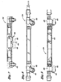
- Figures 3 and 4 show a preferred embodiment of connecting the motion base 22 to the vehicle chassis 24.
- the vehicle chassis 24, shown in Figure 3, provides platforms 43 to which motion base pads 66 are attached. Three motion base pads 66 are attached to three corresponding platforms 43 on the vehicle chassis 24.
- the motion base 22 is connected to the vehicle chassis 24 by six screw type actuators 27. One end of each actuator 27 connects to the motion base 22. The other end of each actuator 27 is connected to base pads 66 which are bolted to the vehicle chassis 24. In this preferred embodiment, three base pads 66 are used with two screw type actuators 27 connected to each base pad 66. Connected to each screw type actuator 27 is an electric motor 26 that powers the screw type actuator 27.
- the passenger cabin 30 is attached to a ring gear 60 of the yaw drive 28 via bolt holes 52.
- the ring gear 60 is turned by a pinion gear 58 driven by an electric motor 56.
- the electric motor 56 drives the passenger cabin 30 via the gears 58 and 60 to rotate around the axis perpendicular to the surface of the motion base 22 (in yaw movement).
- two pinion gears 58 engage the ring gear 60.
- the yaw drive system 28 can provide clockwise or counter-clock wise rotation of the passenger cabin 30.
- the pinion gear 58 and the electric motor 56 are supported on, and corresponding move with, the non-rotating motion base 22.
- the ring gear 60 is fitted into a bearing 62 (i.e. a rolling-element bearing) which connects the yaw drive system 28 and the motion base 22.
- the bearing 62 allows for rotation of the passenger cabin 30 without a corresponding rotation of the motion base 22 or vehicle chassis 24.
- the passenger cabin 30 is provided with six degrees of freedom and bi-directional rotation.
- a slip ring 64 is also provided to transmit audio, video, or other power signals to the passenger cabin 30.
- One end of the slip ring 64 is connected to the non-rotating motion base 22 with the other end connected to the passenger cabin 30.
- the slip ring 64 maintains electrical connections with the passenger cabin 30 regardless of rotation of the passenger cabin.
- circular bus bars or radio communications can be used to transmit audio, video or other signals to the passenger cabin.
- pivot joints 68 are provided to allow angular movement of the screw type actuators 27 relative to the motion base 22 and base pads 66.
- the flexible joints 68 can be any type of joint that allows for angular movement, but, in a preferred embodiment, universal type joints are used.
- the base joints 70 on the base pads 66 and platform joints 72 on the motion base 22 connect to the pivot joints 68.
- the joints 68 in turn are connected to the screw type actuators 27. This allows for angular movement at these connections during engagement of the screw type actuators 27.
- the vehicle chassis 24 is moved along the track 40 on caster wheels 45.
- the wheels 45 have no drive or steering mechanism and the vehicle chassis 24 is pulled along the track 40 by front and rear pairs of opposing pinch wheels 46 pressing against the guide rail 44 and driven by on-board electric motors 49.
- the motors 49 are attached to vehicle chassis 24. Electric power is supplied to the motors 49 via a bus bar or similar design. Any number of vehicles 20 can be attached to the lead vehicle.
- Figure 10 shows the control system 86 for the yaw drive 28, motion base 22, vehicle chassis 24, and power routing (i.e., audio, video, lighting, lap bar mechanism 34, door etc.) to the passenger cabin 30.
- the control system independently regulates the screw type actuators 27, the rotation of the yaw drive system 28 and the vehicle chassis 24 movement, as well as the input to the passenger cabin 30.
- scenery 48 and visual displays on the projection screens 46 along the track 40 are triggered and controlled by a separate control system.
- the control system 86 includes a sub system controller 82, and a cabin PLC system 84.
- the sub system controller 82 controls the actuators, which move the motion base 22, the yaw drive motors 56, and the propulsion motors 49.
- the cabin PLC 84 controls the cabin lighting, audio, lap bar and door actuator systems.
- the passenger cabin 30 has rows of seats 32, with each row holding multiple passengers.
- Laps bars 34 controlled by the cabin PLC system 84, move between open and closed positions.
- the vehicle 20 moves along the track 40 past projection screens 46 that provide different visual effects, for example, motion pictures, that are easily and rapidly changed.
- the passenger cabin 30 is moved in any number of directions and speeds to correspond to the images projected onto the screens 46.
- Scenery 48 e.g. replica's of buildings, vehicles, figures, etc.
- the passenger cabin 30 is moved to interact with the scenery 48.
- the passenger cabin 30 is commanded via the control system to move in the pitch, roll, yaw, heave, surge, and slip directions at variable speeds, accelerations or decelerations.
- the vehicle chassis 24 is also commanded to stop, accelerate or decelerate (forward and backwards).
- the movement of the vehicle chassis 24 is also commanded via the control system to correspond to scenes provided on the projection screens 46 and/or the miscellaneous scenery 48 provided along the track 40.
- the controller commands the passenger cabin 30 to move in almost any direction or rotation and at any velocity, acceleration or deceleration, as well as control the vehicle chassis 24 to stop, accelerate or decelerate (forward and backwards).
- the passenger cabin's 30 movement, as well as the visual and audio effects provided throughout the track 40, are interconnected to give passengers a continuous adventure, with successful completion of the adventure at the end of the ride.
- the vehicle motion base 22, yaw drive system 28 and chassis 24 can be changed to adjust the movement of the passenger cabin 30 to correspond to the new visual effects.
- the yaw drive system can turn the cabin 30 so that the passengers are constantly facing a projecting screen head on, regardless of the movement of the vehicle along the track.
- the cabin 30 can be quickly turned, using the yaw drive system, to have the passengers face another screen.
- the spinning movement provided by the yaw drive system also adds to the thrill of the ride experience.
Landscapes
- Motorcycle And Bicycle Frame (AREA)
- Toys (AREA)
- Addition Polymer Or Copolymer, Post-Treatments, Or Chemical Modifications (AREA)
- Automatic Cycles, And Cycles In General (AREA)
- Passenger Equipment (AREA)
Abstract
Description
Claims (17)
- An amusement ride vehicle (20) including a vehicle chassis (28) and a motion base (22) connected to the vehicle chassis (24), and a yaw drive system, characterized by:the yaw drive system (28), connects the motion base to a passenger cabin (30), with the cabin rotatable 360 degrees relative to the vehicle chassis (24), via the yaw drive system, without movement of the motion base (22);and with the passenger cabin (30) also movable in at least one other degree of freedom via the motion base.
- The amusement ride vehicle of claim 1, further characterized by means for controlling vehicle chassis movement, yaw rotation, motion base movement, and other ride control systems.
- The amusement ride vehicle of claim 1 characterized by six screw type actuators (27) connecting the monon base to the vehicle chassis.
- The amusement ride vehicle of claim 1 characterized by the vehicle chassis is propelled along a predefined track (40).
- The amusement ride vehicle of claim 1 characterized by 2-D and 3-D projections on screens (46) located along the path of the amusement ride vehicle.
- The amusement ride of claim 5 characterized by yaw rotation and motion base movement controlled to correspond with the 2-D and 3-D projections.
- The amusement ride vehicle of claim 1 characterized by fixed or moveable scenery (48) located along the path of the amusement ride vehicle.
- The amusement ride vehicle of claim 1, further characterized by a control system (86), wherein movement of the passenger cabin is triggered by the control system in response to the position of the passenger cabin relative to scenery and projection screens along a path of the amusement ride vehicle.
- The amusement ride vehicle of claim 8 characterized by controlling movement of the passenger cabin by the control system (86) to correlate with fixed and movable scenery located along a path of the vehicle.
- The amusement ride vehicle of claim 1 characterized by the yaw drive system providing the passenger cabin with variable speed clockwise or counter-clockwise rotation.
- The amusement ride vehicle of claims 1 or 10 characterized by the yaw drive system providing the passenger cabin with 360 degrees clockwise or counter-clockwise rotation.
- The amusement ride vehicle of claim 1 characterized by the motion base has multiple degrees of freedom relative to the vehicle chassis.
- The amusement ride vehicle of claim 1 further characterized by:a ring gear rotatably attached to the motion base, with the passenger cabin attached to the ring gear (60); anda pinion gear (58) on a yaw drive motor (56) of the yaw drive system, wherein the pinion gear meshes with the ring gear for turning the passenger cabin relative to the motion base.
- The amusement ride vehicle of claim 13 with the motion base further characterized by actuators (27) for moving the passenger cabin in at least one of pitch, roll, heave; surge, and slip movements.
- The amusement ride attraction of claim 14 further characterized by an electronic control system (86) linked to the actuators and to the yaw drive motor, for controlling and coordinating movement of the passenger cabin.
- The amusement ride vehicle of claim 1 with the yaw drive system (28) characterized by:a yaw ring (60) rotatably attached to the motion base, with the passenger cabin attached to the yaw ring;a slip ring assembly (64) having a first end fixed to the motion base and a second end fixed to the passenger cabin, wherein the first end of the slip ring assembly is rotatably attached to the second end; anda yaw drive motor (56) linked to the yaw ring for turning the passenger cabin on the motion base.
- The amusement ride vehicle of claim 16 with the yaw ring characterized by a ring gear (60).
Applications Claiming Priority (3)
| Application Number | Priority Date | Filing Date | Title |
|---|---|---|---|
| US09/070,950 US6095926A (en) | 1998-05-01 | 1998-05-01 | Amusement ride vehicle |
| US70950 | 1998-05-01 | ||
| PCT/US1999/009026 WO1999056846A1 (en) | 1998-05-01 | 1999-04-26 | Amusement ride vehicle |
Publications (3)
| Publication Number | Publication Date |
|---|---|
| EP1079906A1 EP1079906A1 (en) | 2001-03-07 |
| EP1079906A4 EP1079906A4 (en) | 2004-05-12 |
| EP1079906B1 true EP1079906B1 (en) | 2005-12-28 |
Family
ID=22098346
Family Applications (1)
| Application Number | Title | Priority Date | Filing Date |
|---|---|---|---|
| EP99920036A Expired - Lifetime EP1079906B1 (en) | 1998-05-01 | 1999-04-26 | Amusement ride vehicle |
Country Status (8)
| Country | Link |
|---|---|
| US (1) | US6095926A (en) |
| EP (1) | EP1079906B1 (en) |
| JP (1) | JP4356052B2 (en) |
| AT (1) | ATE314126T1 (en) |
| AU (1) | AU3762299A (en) |
| DE (1) | DE69929187T2 (en) |
| ES (1) | ES2257046T3 (en) |
| WO (1) | WO1999056846A1 (en) |
Cited By (2)
| Publication number | Priority date | Publication date | Assignee | Title |
|---|---|---|---|---|
| CN105659306A (en) * | 2013-06-13 | 2016-06-08 | 阿姆斯特-系统科技有限责任公司 | Self-propelled, highly dynamic driving simulator |
| US9757658B1 (en) | 2016-04-19 | 2017-09-12 | Simtech Systems Gmbh | Fairground ride |
Families Citing this family (82)
| Publication number | Priority date | Publication date | Assignee | Title |
|---|---|---|---|---|
| US6445960B1 (en) * | 1998-05-29 | 2002-09-03 | Ronbotics Corporation | Electric motion platform and a control system for controlling the same |
| US7749089B1 (en) | 1999-02-26 | 2010-07-06 | Creative Kingdoms, Llc | Multi-media interactive play system |
| US6761637B2 (en) | 2000-02-22 | 2004-07-13 | Creative Kingdoms, Llc | Method of game play using RFID tracking device |
| US7878905B2 (en) | 2000-02-22 | 2011-02-01 | Creative Kingdoms, Llc | Multi-layered interactive play experience |
| US7445550B2 (en) | 2000-02-22 | 2008-11-04 | Creative Kingdoms, Llc | Magical wand and interactive play experience |
| JP2004503308A (en) * | 2000-06-16 | 2004-02-05 | ロボコースター・リミテッド | Vehicle equipment |
| US6487975B1 (en) * | 2000-08-21 | 2002-12-03 | Jonathan I. Gordon | Roller coaster car having a force-isolated passenger compartment |
| US6371853B1 (en) | 2000-08-25 | 2002-04-16 | Ronbotics Corporation | Motion pinball game |
| US7066781B2 (en) | 2000-10-20 | 2006-06-27 | Denise Chapman Weston | Children's toy with wireless tag/transponder |
| JP2002253868A (en) * | 2001-02-28 | 2002-09-10 | Hitachi Ltd | Content distribution system for simulation ride system, distribution device for ride content management center, simulation ride control device, and computer software |
| US6796908B2 (en) | 2001-06-14 | 2004-09-28 | Creative Kingdoms, Llc | Interactive dark ride |
| US6632092B2 (en) | 2001-06-22 | 2003-10-14 | Gregory Kristen Moran | Propelled-pivoting motion base with rotating disc and method |
| KR100366179B1 (en) * | 2001-08-29 | 2003-01-06 | (주)데코스인터렉티브 | Motion simulation pad |
| US20070066396A1 (en) | 2002-04-05 | 2007-03-22 | Denise Chapman Weston | Retail methods for providing an interactive product to a consumer |
| US6967566B2 (en) | 2002-04-05 | 2005-11-22 | Creative Kingdoms, Llc | Live-action interactive adventure game |
| US9446319B2 (en) | 2003-03-25 | 2016-09-20 | Mq Gaming, Llc | Interactive gaming toy |
| US7094157B2 (en) * | 2003-07-22 | 2006-08-22 | Oceaneering International, Inc. | Amusement ride vehicle with pneumatically actuated cabin and motion base |
| DE10350059B4 (en) * | 2003-10-27 | 2011-02-10 | Stefan Hinzmann | event arrangement |
| US6964614B1 (en) * | 2004-10-26 | 2005-11-15 | Tonic Fitness Technology, Inc. | Riding device |
| US20060121420A1 (en) * | 2004-11-18 | 2006-06-08 | Michael Athanas | Pilot seat positioning device |
| US20060135271A1 (en) * | 2004-12-17 | 2006-06-22 | Casey Joseph F | Amusement ride vehicle with sensory stimulation effects |
| DE102004062315A1 (en) * | 2004-12-20 | 2006-06-29 | Mack Ride Gmbh & Co Kg | Water ride |
| TW200718457A (en) * | 2005-08-18 | 2007-05-16 | Aruze Corp | Gaming machine and terminal device included in gaming machine |
| US7484460B2 (en) * | 2005-09-30 | 2009-02-03 | Universal City Studios Lllp | Amusement ride track with motion base |
| CA2648224A1 (en) * | 2006-04-14 | 2007-10-25 | Creative Kingdoms, Llc | Interactive waterplay apparatus and methods |
| US8141452B2 (en) * | 2006-10-26 | 2012-03-27 | Barry Lynn Wood | Rotational motion-positioning apparatus |
| US7694640B2 (en) * | 2006-12-21 | 2010-04-13 | Universal City Studios Lllp | Guest positioning assembly |
| US20080150345A1 (en) * | 2006-12-21 | 2008-06-26 | Blum Steven C | Guest Positioning Assembly |
| US7506602B2 (en) * | 2006-12-21 | 2009-03-24 | Universal City Studios Lllp | Guest positioning assembly |
| DE102007001881A1 (en) * | 2007-01-12 | 2008-07-17 | Franz Xaver Heinrich | Ride, especially roller coaster |
| US8151660B2 (en) | 2007-02-23 | 2012-04-10 | RPY Motion, Inc. | Three axes rotational motion-positioning apparatus |
| US7610859B1 (en) | 2007-06-30 | 2009-11-03 | Jordan Reder Dietrich | Carriage rotatable roller coaster tracks and vehicles |
| US7967688B2 (en) * | 2009-01-16 | 2011-06-28 | Brogent Technologies, Inc. | Motion simulator |
| EP2210652A1 (en) * | 2009-01-21 | 2010-07-28 | Brogent Technologies, inc. | Motion simulator |
| CN101766910B (en) * | 2010-01-05 | 2011-11-30 | 中山市红阳娱乐设备有限公司 | Pneumatic power wobbler |
| US20110276156A1 (en) * | 2010-05-10 | 2011-11-10 | Continental Automotive Systems, Inc. | 4D Vehicle Entertainment System |
| US8636600B2 (en) * | 2010-06-24 | 2014-01-28 | Disney Enterprises, Inc. | Roller coaster vehicle |
| EP2510989B1 (en) * | 2011-04-13 | 2013-04-10 | Brogent Technologies, inc. | Lateral dynamic simulation device |
| EP2707863B1 (en) * | 2011-05-11 | 2018-08-01 | Oceaneering International, Inc. | Trackless dark ride vehicle, system, and method |
| US8689698B2 (en) * | 2011-06-08 | 2014-04-08 | Dennis Shasha | Methods and systems for multi-dimensional motion |
| US8641540B2 (en) | 2011-07-13 | 2014-02-04 | Roland Feuer | Inverted simulation attraction |
| US8578857B2 (en) | 2011-12-08 | 2013-11-12 | Disney Enterprises, Inc. | Amusement park ride with passenger loading separated from vehicle insertion into simulators |
| CN103816663A (en) * | 2011-12-31 | 2014-05-28 | 浙江省东阳市东亚工具有限公司 | Climbing fun device |
| TWM442183U (en) * | 2012-05-07 | 2012-12-01 | Injoy Motion Corp | Decoupling two-axis motion platform |
| US9616349B2 (en) * | 2012-11-07 | 2017-04-11 | Oceaneering International, Inc. | Method of managing loading, unloading, and routing of trackless vehicles and system using the same |
| DK3539629T3 (en) * | 2013-03-15 | 2021-01-25 | Oceaneering Int Inc | RAIL-FREE VEHICLE AND SYSTEM FOR SYNCHRONIC CONTROL OF RAIL-FREE VEHICLE |
| US9916717B2 (en) | 2013-06-12 | 2018-03-13 | Joze Pececnik | Holographic amusement/wagering system with vehicular user transport |
| CN103691134B (en) * | 2013-12-30 | 2015-09-09 | 深圳华侨城文化旅游科技股份有限公司 | A kind of Platform-type kinetic car |
| CN103736285B (en) * | 2013-12-30 | 2015-09-09 | 深圳华侨城文化旅游科技股份有限公司 | A kind of viewing system based on double-deck video display railcar |
| CN104027980B (en) * | 2014-05-19 | 2016-04-06 | 温州南方游乐设备工程有限公司 | A kind of chassis of riding dynamic car |
| US9526997B2 (en) | 2014-07-22 | 2016-12-27 | Universal City Studios Llc | Vehicle transportation room system and method |
| US9084941B1 (en) | 2014-09-22 | 2015-07-21 | Eric Fram | Combination ride for amusement park |
| US10758831B2 (en) | 2014-11-17 | 2020-09-01 | Whitewater West Industries Ltd. | Interactive play center with interactive elements and consequence elements |
| CN104401247A (en) * | 2014-11-28 | 2015-03-11 | 重庆欧派信息科技有限责任公司 | Movable 4D popular science propaganda vehicle |
| WO2017021340A1 (en) * | 2015-07-31 | 2017-02-09 | Antonio Zamperla S.P.A. | Amusement ride vehicle having a rotatable passenger support frame |
| US10099149B2 (en) | 2015-10-02 | 2018-10-16 | Universal City Studios Llc | Amusement park ride tunnel |
| US9610511B1 (en) * | 2015-12-16 | 2017-04-04 | Disney Enterprises, Inc. | Amusement park ride vehicle including a chassis driven to have heave and sway motions |
| WO2017141170A1 (en) * | 2016-02-17 | 2017-08-24 | Kyneprox S.R.L. | Inertial platform |
| US10144616B2 (en) * | 2016-06-10 | 2018-12-04 | Otis Elevator Company | Cab for vertical travel with controllable orientation for non-vertical travel |
| WO2018071728A1 (en) | 2016-10-13 | 2018-04-19 | Positron, Llc | Controlled dynamic multi-axis virtual reality system |
| CA3299594A1 (en) | 2016-11-14 | 2026-03-02 | Whitewater West Industries Ltd. | Play Center Using Structural Monoliths For Water Delivery Capabilities |
| JP6178952B1 (en) * | 2017-01-31 | 2017-08-09 | 泉陽興業株式会社 | Oscillating device and amusement facility equipped with the same |
| KR102144243B1 (en) * | 2017-02-08 | 2020-08-12 | 유니버셜 시티 스튜디오스 엘엘씨 | Movement generating platform assembly |
| NL2018935B1 (en) * | 2017-05-17 | 2018-11-28 | Vekoma Rides Eng B V | Suspended rollercoaster vehicle with rotational lockage |
| US9981194B1 (en) * | 2017-06-30 | 2018-05-29 | Falcon's Treehouse Llc | Motion base for ride attraction or theater |
| US10350503B2 (en) * | 2017-09-25 | 2019-07-16 | Universal City Studios Llc | Amusement park capsule ride |
| US10525364B2 (en) * | 2017-11-07 | 2020-01-07 | Universal City Studios Llc | Speed simulation effect |
| US10293265B1 (en) * | 2017-11-07 | 2019-05-21 | Universal City Studios Llc | Systems and methods for a sphere ride |
| US11439921B2 (en) * | 2018-06-25 | 2022-09-13 | Universal City Studios Llc | Multi-dimensional bogie and track system |
| USD898151S1 (en) * | 2018-12-26 | 2020-10-06 | Niraj Ashok Rawal | Flight simulator |
| US10463981B1 (en) * | 2018-12-27 | 2019-11-05 | Universal City Studios Llc | Ride vehicle elevator and motion actuation |
| EP3715224B1 (en) * | 2019-03-29 | 2022-10-05 | Ningbo Geely Automobile Research & Development Co. Ltd. | A vehicle and a method of simulating a drifting/skidding movement of a vehicle |
| CN110465077A (en) * | 2019-06-11 | 2019-11-19 | 江苏博人文化科技有限公司 | Virtual reality multiple degrees of freedom amusement experience system |
| JP7297151B2 (en) * | 2020-07-03 | 2023-06-23 | 深▲せん▼怡豊自動化科技有限公司 | AGV recreational transport tool and connection assembly |
| CN111846019B (en) * | 2020-07-03 | 2024-08-30 | 深圳怡丰自动化科技有限公司 | AGV amusement transport means and coupling assembling |
| USD974514S1 (en) * | 2021-05-17 | 2023-01-03 | Niraj Ashok Rawal | Flight simulator |
| TWI782596B (en) * | 2021-06-26 | 2022-11-01 | 智崴資訊科技股份有限公司 | Motion simulating apparatus |
| US12337249B2 (en) * | 2021-07-06 | 2025-06-24 | Universal City Studios Llc | Systems and methods for a multi-degree of freedom ride vehicle |
| WO2023283041A1 (en) * | 2021-07-06 | 2023-01-12 | Universal City Studios Llc | Systems and methods for a multi-degree of freedom ride vehicle |
| DE202021103837U1 (en) | 2021-07-19 | 2022-10-25 | Raw Tex International Establishment | wobble arrangement |
| WO2023091757A1 (en) * | 2021-11-22 | 2023-05-25 | Universal City Studios Llc | Conveyor systems with animated elements |
| US20240269573A1 (en) * | 2023-02-10 | 2024-08-15 | Universal City Studios Llc | Path transfer attraction system for amusement park |
Family Cites Families (20)
| Publication number | Priority date | Publication date | Assignee | Title |
|---|---|---|---|---|
| US717457A (en) * | 1902-11-14 | 1902-12-30 | George W Schofield | Amusement apparatus. |
| US771322A (en) * | 1903-12-05 | 1904-10-04 | Planets Company | Ball-coaster. |
| US815211A (en) * | 1905-05-25 | 1906-03-13 | Herbert H Pattee | Amusement-vehicle. |
| US814939A (en) * | 1905-10-06 | 1906-03-13 | Frank A Cerruti | Amusement-railway. |
| US858624A (en) * | 1906-11-01 | 1907-07-02 | John C Reckweg | Pleasure-railway. |
| US852184A (en) * | 1906-12-15 | 1907-04-30 | Roland Hunt | Pleasure-railway. |
| US921416A (en) * | 1909-01-20 | 1909-05-11 | August P Lauster | Amusement device. |
| US1397009A (en) * | 1920-12-07 | 1921-11-15 | Emma C Maynes | Amusement apparatus |
| US2535862A (en) * | 1947-06-12 | 1950-12-26 | Bernard B Pewitt | Vertical and horizontal axes roundabout |
| US3669026A (en) * | 1970-05-18 | 1972-06-13 | Geoscience Ltd | Transportation system |
| US4170943A (en) * | 1977-08-01 | 1979-10-16 | Achrekar Prakash M | Roller coaster assembly |
| US4303236A (en) * | 1980-07-28 | 1981-12-01 | Kinop International, Inc. | Trip motion simulator |
| DE3523635A1 (en) * | 1984-07-03 | 1986-02-27 | Concorde St. George Productions Pty. Ltd., South Melbourne, Victoria | PLEASURE DEVICE |
| US4856771A (en) * | 1987-10-22 | 1989-08-15 | Nelson, Berg Enterprises | Video simulation apparatus |
| US5060932A (en) * | 1989-05-25 | 1991-10-29 | Nisshinbo Techno Vehicle Inc. | Amusement apparatus having rotary capsule |
| US5453053A (en) * | 1993-07-15 | 1995-09-26 | The Walt Disney Company | Amusement ride having spinning passenger cars |
| US5473990A (en) * | 1993-08-19 | 1995-12-12 | The Walt Disney Company | Ride vehicle control system |
| US5669821A (en) * | 1994-04-12 | 1997-09-23 | Prather; James G. | Video augmented amusement rides |
| US5558582A (en) * | 1994-10-14 | 1996-09-24 | Enhanced Simulation, Inc. | Rotating motion simulator |
| US5556340A (en) * | 1995-08-25 | 1996-09-17 | The Walt Disney Company | Amusement ride assembly with rotating tube synchronized with an image |
-
1998
- 1998-05-01 US US09/070,950 patent/US6095926A/en not_active Expired - Lifetime
-
1999
- 1999-04-26 AU AU37622/99A patent/AU3762299A/en not_active Abandoned
- 1999-04-26 AT AT99920036T patent/ATE314126T1/en not_active IP Right Cessation
- 1999-04-26 ES ES99920036T patent/ES2257046T3/en not_active Expired - Lifetime
- 1999-04-26 DE DE69929187T patent/DE69929187T2/en not_active Expired - Lifetime
- 1999-04-26 JP JP2000546860A patent/JP4356052B2/en not_active Expired - Lifetime
- 1999-04-26 WO PCT/US1999/009026 patent/WO1999056846A1/en not_active Ceased
- 1999-04-26 EP EP99920036A patent/EP1079906B1/en not_active Expired - Lifetime
Cited By (2)
| Publication number | Priority date | Publication date | Assignee | Title |
|---|---|---|---|---|
| CN105659306A (en) * | 2013-06-13 | 2016-06-08 | 阿姆斯特-系统科技有限责任公司 | Self-propelled, highly dynamic driving simulator |
| US9757658B1 (en) | 2016-04-19 | 2017-09-12 | Simtech Systems Gmbh | Fairground ride |
Also Published As
| Publication number | Publication date |
|---|---|
| DE69929187D1 (en) | 2006-02-02 |
| JP4356052B2 (en) | 2009-11-04 |
| US6095926A (en) | 2000-08-01 |
| ATE314126T1 (en) | 2006-01-15 |
| JP2002513663A (en) | 2002-05-14 |
| WO1999056846A1 (en) | 1999-11-11 |
| EP1079906A4 (en) | 2004-05-12 |
| DE69929187T2 (en) | 2006-08-24 |
| AU3762299A (en) | 1999-11-23 |
| EP1079906A1 (en) | 2001-03-07 |
| ES2257046T3 (en) | 2006-07-16 |
Similar Documents
| Publication | Publication Date | Title |
|---|---|---|
| US6095926A (en) | Amusement ride vehicle | |
| JP5457432B2 (en) | Amusement park vehicles with vehicles that turn around a common chassis to provide racing and other effects | |
| US5623878A (en) | Dynamic ride vehicle | |
| EP0667798B1 (en) | Amusement park attraction | |
| EP1311330B1 (en) | Amusement ride with pivotable motion base | |
| EP1652163B1 (en) | Amusement ride vehicle with pneumatically actuated cabin and motion base | |
| CN107303434B (en) | Amusement park riding device | |
| JP7579814B2 (en) | Motion System | |
| JP2002513663A5 (en) | ||
| JP2731129B2 (en) | Suspended mobile unit | |
| JP4202487B2 (en) | Shooting game equipment | |
| JPH0683095U (en) | Entertainment vehicle | |
| HK1105543B (en) | Amusement ride vehicle with pneumatically actuated cabin and motion base |
Legal Events
| Date | Code | Title | Description |
|---|---|---|---|
| PUAI | Public reference made under article 153(3) epc to a published international application that has entered the european phase |
Free format text: ORIGINAL CODE: 0009012 |
|
| 17P | Request for examination filed |
Effective date: 20001130 |
|
| AK | Designated contracting states |
Kind code of ref document: A1 Designated state(s): AT BE CH CY DE DK ES FI FR GB GR IE IT LI LU MC NL PT SE |
|
| RIC1 | Information provided on ipc code assigned before grant |
Ipc: 7A 63G 31/00 B Ipc: 7A 63G 31/04 A |
|
| A4 | Supplementary search report drawn up and despatched |
Effective date: 20040324 |
|
| 17Q | First examination report despatched |
Effective date: 20040723 |
|
| GRAP | Despatch of communication of intention to grant a patent |
Free format text: ORIGINAL CODE: EPIDOSNIGR1 |
|
| GRAS | Grant fee paid |
Free format text: ORIGINAL CODE: EPIDOSNIGR3 |
|
| GRAA | (expected) grant |
Free format text: ORIGINAL CODE: 0009210 |
|
| AK | Designated contracting states |
Kind code of ref document: B1 Designated state(s): AT BE CH CY DE DK ES FI FR GB GR IE IT LI LU MC NL PT SE |
|
| PG25 | Lapsed in a contracting state [announced via postgrant information from national office to epo] |
Ref country code: NL Free format text: LAPSE BECAUSE OF FAILURE TO SUBMIT A TRANSLATION OF THE DESCRIPTION OR TO PAY THE FEE WITHIN THE PRESCRIBED TIME-LIMIT Effective date: 20051228 Ref country code: FI Free format text: LAPSE BECAUSE OF FAILURE TO SUBMIT A TRANSLATION OF THE DESCRIPTION OR TO PAY THE FEE WITHIN THE PRESCRIBED TIME-LIMIT Effective date: 20051228 Ref country code: BE Free format text: LAPSE BECAUSE OF FAILURE TO SUBMIT A TRANSLATION OF THE DESCRIPTION OR TO PAY THE FEE WITHIN THE PRESCRIBED TIME-LIMIT Effective date: 20051228 Ref country code: AT Free format text: LAPSE BECAUSE OF FAILURE TO SUBMIT A TRANSLATION OF THE DESCRIPTION OR TO PAY THE FEE WITHIN THE PRESCRIBED TIME-LIMIT Effective date: 20051228 |
|
| REG | Reference to a national code |
Ref country code: GB Ref legal event code: FG4D |
|
| REG | Reference to a national code |
Ref country code: CH Ref legal event code: EP |
|
| REG | Reference to a national code |
Ref country code: IE Ref legal event code: FG4D |
|
| REF | Corresponds to: |
Ref document number: 69929187 Country of ref document: DE Date of ref document: 20060202 Kind code of ref document: P |
|
| REG | Reference to a national code |
Ref country code: CH Ref legal event code: NV Representative=s name: SERVOPATENT GMBH |
|
| PG25 | Lapsed in a contracting state [announced via postgrant information from national office to epo] |
Ref country code: SE Free format text: LAPSE BECAUSE OF FAILURE TO SUBMIT A TRANSLATION OF THE DESCRIPTION OR TO PAY THE FEE WITHIN THE PRESCRIBED TIME-LIMIT Effective date: 20060328 Ref country code: GR Free format text: LAPSE BECAUSE OF FAILURE TO SUBMIT A TRANSLATION OF THE DESCRIPTION OR TO PAY THE FEE WITHIN THE PRESCRIBED TIME-LIMIT Effective date: 20060328 Ref country code: DK Free format text: LAPSE BECAUSE OF FAILURE TO SUBMIT A TRANSLATION OF THE DESCRIPTION OR TO PAY THE FEE WITHIN THE PRESCRIBED TIME-LIMIT Effective date: 20060328 |
|
| PG25 | Lapsed in a contracting state [announced via postgrant information from national office to epo] |
Ref country code: IE Free format text: LAPSE BECAUSE OF NON-PAYMENT OF DUE FEES Effective date: 20060426 |
|
| PG25 | Lapsed in a contracting state [announced via postgrant information from national office to epo] |
Ref country code: MC Free format text: LAPSE BECAUSE OF NON-PAYMENT OF DUE FEES Effective date: 20060430 |
|
| PG25 | Lapsed in a contracting state [announced via postgrant information from national office to epo] |
Ref country code: PT Free format text: LAPSE BECAUSE OF FAILURE TO SUBMIT A TRANSLATION OF THE DESCRIPTION OR TO PAY THE FEE WITHIN THE PRESCRIBED TIME-LIMIT Effective date: 20060529 |
|
| NLV1 | Nl: lapsed or annulled due to failure to fulfill the requirements of art. 29p and 29m of the patents act | ||
| REG | Reference to a national code |
Ref country code: ES Ref legal event code: FG2A Ref document number: 2257046 Country of ref document: ES Kind code of ref document: T3 |
|
| ET | Fr: translation filed | ||
| PLBE | No opposition filed within time limit |
Free format text: ORIGINAL CODE: 0009261 |
|
| STAA | Information on the status of an ep patent application or granted ep patent |
Free format text: STATUS: NO OPPOSITION FILED WITHIN TIME LIMIT |
|
| 26N | No opposition filed |
Effective date: 20060929 |
|
| REG | Reference to a national code |
Ref country code: IE Ref legal event code: MM4A |
|
| REG | Reference to a national code |
Ref country code: CH Ref legal event code: PFA Owner name: UNIVERSAL STUDIOS, INC. Free format text: UNIVERSAL STUDIOS, INC.#BUILDING 488, 7TH FLOOR, 100 UNIVERSAL CITY PLAZA#UNIVERSAL CITY, CA 91608 (US) -TRANSFER TO- UNIVERSAL STUDIOS, INC.#BUILDING 488, 7TH FLOOR, 100 UNIVERSAL CITY PLAZA#UNIVERSAL CITY, CA 91608 (US) |
|
| PG25 | Lapsed in a contracting state [announced via postgrant information from national office to epo] |
Ref country code: LU Free format text: LAPSE BECAUSE OF NON-PAYMENT OF DUE FEES Effective date: 20060426 |
|
| PG25 | Lapsed in a contracting state [announced via postgrant information from national office to epo] |
Ref country code: CY Free format text: LAPSE BECAUSE OF FAILURE TO SUBMIT A TRANSLATION OF THE DESCRIPTION OR TO PAY THE FEE WITHIN THE PRESCRIBED TIME-LIMIT Effective date: 20051228 |
|
| REG | Reference to a national code |
Ref country code: FR Ref legal event code: PLFP Year of fee payment: 18 |
|
| REG | Reference to a national code |
Ref country code: FR Ref legal event code: PLFP Year of fee payment: 19 |
|
| REG | Reference to a national code |
Ref country code: FR Ref legal event code: PLFP Year of fee payment: 20 |
|
| PGFP | Annual fee paid to national office [announced via postgrant information from national office to epo] |
Ref country code: CH Payment date: 20180502 Year of fee payment: 20 Ref country code: DE Payment date: 20180427 Year of fee payment: 20 Ref country code: ES Payment date: 20180503 Year of fee payment: 20 |
|
| PGFP | Annual fee paid to national office [announced via postgrant information from national office to epo] |
Ref country code: IT Payment date: 20180423 Year of fee payment: 20 Ref country code: FR Payment date: 20180425 Year of fee payment: 20 |
|
| PGFP | Annual fee paid to national office [announced via postgrant information from national office to epo] |
Ref country code: GB Payment date: 20180427 Year of fee payment: 20 |
|
| REG | Reference to a national code |
Ref country code: DE Ref legal event code: R071 Ref document number: 69929187 Country of ref document: DE |
|
| REG | Reference to a national code |
Ref country code: CH Ref legal event code: PL |
|
| REG | Reference to a national code |
Ref country code: GB Ref legal event code: PE20 Expiry date: 20190425 |
|
| PG25 | Lapsed in a contracting state [announced via postgrant information from national office to epo] |
Ref country code: GB Free format text: LAPSE BECAUSE OF EXPIRATION OF PROTECTION Effective date: 20190425 |
|
| REG | Reference to a national code |
Ref country code: ES Ref legal event code: FD2A Effective date: 20220103 |
|
| PG25 | Lapsed in a contracting state [announced via postgrant information from national office to epo] |
Ref country code: ES Free format text: LAPSE BECAUSE OF EXPIRATION OF PROTECTION Effective date: 20190427 |