EP1079608A2 - Imaging apparatus with noise reduction function - Google Patents
Imaging apparatus with noise reduction function Download PDFInfo
- Publication number
- EP1079608A2 EP1079608A2 EP00307333A EP00307333A EP1079608A2 EP 1079608 A2 EP1079608 A2 EP 1079608A2 EP 00307333 A EP00307333 A EP 00307333A EP 00307333 A EP00307333 A EP 00307333A EP 1079608 A2 EP1079608 A2 EP 1079608A2
- Authority
- EP
- European Patent Office
- Prior art keywords
- image signal
- noise reduction
- memory
- imaging
- vertical scanning
- Prior art date
- Legal status (The legal status is an assumption and is not a legal conclusion. Google has not performed a legal analysis and makes no representation as to the accuracy of the status listed.)
- Granted
Links
Images
















Classifications
-
- H—ELECTRICITY
- H04—ELECTRIC COMMUNICATION TECHNIQUE
- H04N—PICTORIAL COMMUNICATION, e.g. TELEVISION
- H04N23/00—Cameras or camera modules comprising electronic image sensors; Control thereof
- H04N23/80—Camera processing pipelines; Components thereof
- H04N23/81—Camera processing pipelines; Components thereof for suppressing or minimising disturbance in the image signal generation
Definitions
- the present invention generally relates to an imaging apparatus, and particularly to an imaging apparatus having a picture memory function to simultaneously achieve a recursive noise reduction circuit (hereinafter, referred to simply as "recursive NR circuit"), and long time accumulation (accumulation sensitivity increase) of CCD.
- recursive NR circuit recursive noise reduction circuit
- long time accumulation accumulation sensitivity increase
- JP-A-5-236312 describes various functions using a recursive NR circuit and a memory system. Particularly, in the second noise reduction mode, the noise reduction effect is achieved by the recursive NR circuit and the accumulation sensitivity increase over 2-field periods.
- Fig. 38 is a schematic block diagram of a conventional imaging apparatus.
- the imaging apparatus shown in Fig. 38 includes: a CCD 101 for converting a light image into an electrical image signal; a CDS 102 for sampling the electrical image signal; an A/D circuit 103 for converting the sampled image signal into a digital signal; a recursive NR circuit 104 that performs the recursive filtering process to the digital image signal in the time-axis direction to reduce the noise component of the image signal; a digital process circuit 105 that performs the necessary signal process to the recursive-filtered image signal; a D/A circuit 106 that converts the processed image signal into an analog signal to be output; a field memory 107 for storing an output signal of the recursive NR circuit 104; a field memory control circuit 108 for controlling the field memory 107; and a microcomputer 109 for controlling the whole imaging apparatus.
- the field memory control circuit 108 delays the output signal of the recursive NR circuit 104 by one vertical scanning period, and outputs this delayed signal to the recursive NR circuit 104 as a cyclic signal.
- the microcomputer 109 controls the cyclic coefficient of the recursive NR circuit 104, and controls the field memory control circuit 108 to write to and read from the field memory 107.
- the CCD 101 is controlled by a charge reading pulse from a timing control circuit 110.
- the accumulation sensitivity increase is achieved when the microcomputer 109 controls the accumulation time that is input to the timing control circuit 110.
- Fig. 39 is a timing chart showing the operation timing of this imaging apparatus in the normal operation.
- the timing control circuit 110 outputs the charge reading pulse to the CCD 101 every vertical scanning period, so that the image signal is output from the CCD 101.
- the cyclic coefficient K which is input from the microcomputer 109 to the recursive NR circuit 104 is set to be k.
- the recursive NR circuit 104 performs the arithmetic operation using the image signal x and an output signal X-2 of the field memory 107 to output the result as an output signal X.
- the output signal X is written to the field memory 107.
- the cyclic coefficient K which is input from the microcomputer 109 to the recursive NR circuit 104 is set to be "0". Consequently, the output signal X of the field memory 107 is output from the recursive NR circuit 104 as the output signal X as it is. At this time, the output signal X of the recursive NR circuit 104 is not written to the field memory 107.
- Fig. 40 is a timing chart showing the operation timing of this imaging apparatus in a 2-times accumulation sensitivity increase operation.
- the timing control circuit 110 outputs the charge reading pulse to the CCD 101 every two vertical scanning periods. Therefore, the CCD 101 accumulates charges for two vertical scanning periods, and outputs the accumulated charges as an image signal.
- the cyclic coefficient K which is input from the microcomputer 109 to the recursive NR circuit 104 is set to be k.
- the recursive NR circuit 104 performs the arithmetic operation using the image signal x and an output signal X-2 of the field memory 107 to output the result as an output signal X.
- the output signal X is written to the field memory 107.
- the timing control circuit 110 When an image signal x+1 is output from the CCD 101, the timing control circuit 110 outputs no charge reading pulse, and hence the CCD 101 outputs no image signal.
- the cyclic coefficient K which is input from the microcomputer 109 to the recursive NR circuit 104 is set to be "0" so that the output signal X of the field memory 107 is output from the recursive NR circuit 104 as the output signal X as it is.
- the output signal X of the recursive NR circuit 104 is not written to the field memory 107.
- the accumulation sensitivity can be increased twice, and at the same time the recursive NR can be achieved. Both of the sensitivity increase and the noise reduction can be attained.
- the recursive NR is performed using the filed memory 107, and the noise reduction operation by the recursive NR in the normal operation is performed by circulation of only one-field signal of the interlaced signal with the other-field signal not used.
- the vertical resolution is deteriorated.
- uncomfortable feeling occurs in the recursive NR operation.
- an imaging apparatus includes:
- This imaging apparatus may use the memory means such as a frame memory, and performs the recursive noise reduction process to the both-fields signal of the interlaced signal in the normal operation. Thereby, it is possible to reduce noise without deteriorating the vertical resolution. Further, even if the imaging means such as a CCD performs the 2n-times long time accumulation (or the accumulation sensitivity increase), it is possible to make the recursive noise reduction means operate properly.
- the recursive noise reduction means when the long time accumulation in the imaging means changes from one-time to 2n-times, after 2n vertical scanning periods from this change, the recursive noise reduction means outputs the image signal from the imaging means as the output signal as it is, without performing the noise reduction process.
- the recursive noise reduction means outputs the image signal from the imaging means as the output signal as it is, without performing the noise reduction process. Thereby, it is possible to prevent the recursive noise reduction means from the erroneous operation. Further, it is possible to change the one-time accumulation sensitivity increase operation to the 2n-times accumulation sensitivity increase operation without any uncomfortable feeling.
- the recursive noise reduction means when the long time accumulation in the imaging means changes from 2m-times (m is an integer of "1" or more, m ⁇ n) to 2n-times, after 2n vertical scanning periods from this change, the recursive noise reduction means outputs the image signal from the imaging means as the output signal as it is, without performing the noise reduction process.
- the recursive noise reduction means outputs the image signal from the imaging means as the output signal as it is, without performing the noise reduction process. Thereby, it is possible to prevent the recursive noise reduction means from the erroneous operation. Further, it is possible to change from the 2m-times accumulation sensitivity increase operation to the 2n-times accumulation sensitivity increase operation without any uncomfortable feeling.
- the recursive noise reduction means when the long time accumulation in the imaging means changes from 2n-times to one-time, in a vertical scanning period after one vertical scanning period from this change, the recursive noise reduction means outputs the image signal from the imaging means as the output signal as it is, without performing the noise reduction process.
- the recursive noise reduction means outputs the image signal from the imaging means as the output signal as it is, without performing the noise reduction process. Thereby, it is possible to prevent the recursive noise reduction means from the erroneous operation. Further, it is possible to change from the 2n-times accumulation sensitivity increase operation to the one-time accumulation sensitivity increase operation without any uncomfortable feeling.
- the recursive noise reduction means when the long time accumulation in the imaging means changes from 2n-times to one-time, in two or more vertical scanning periods after one vertical scanning period from this change, the recursive noise reduction means outputs the image signal from the imaging means as the output signal as it is, without performing the noise reduction process.
- the recursive noise reduction means outputs the image signal from the imaging means as the output signal as it is, without performing the noise reduction process. Thereby, it is possible to prevent the recursive noise reduction means from the uncomfortable feeling in operation. Further, it is possible to remove the uncomfortable feeling between the fields of the interlaced signal in the two vertical scanning periods.
- the memory control means reads out an image signal of an opposite field stored in the memory means, and makes the recursive noise reduction means perform the noise reduction process on the basis of the read-out image signal of the opposite field and the image signal from the imaging means.
- the memory control means reads out an image signal of an opposite field stored in the memory means, and makes the recursive noise reduction means perform the noise reduction process on the basis of the read-out image signal of the opposite field and the image signal from the imaging means.
- the memory control means reads out an image signal of an opposite field stored in the memory means, makes vertical-phase correction means perform a vertical-phase correction process to correct the read-out image signal of the opposite field for 1/2 line spatial phase shift, and makes the recursive noise reduction means perform the noise reduction process on the basis of the vertical-phase-correction processed image signal and the image signal from the imaging means.
- the memory control means reads out an image signal of an opposite field stored in the memory means, makes vertical-phase correction means perform a vertical-phase correction process to correct the read-out image signal of the opposite field for 1/2 line spatial phase shift, and makes the recursive noise reduction means perform the noise reduction process on the basis of the vertical-phase-correction processed image signal and the image signal from the imaging means.
- An imaging apparatus further comprises two of the memory means, wherein when the imaging means performs the long time accumulation, in a vertical scanning period in which the image signal is output from the imaging means, the memory control means writes the image signal generated by the recursive noise reduction means to each memory means.
- the memory control means writes the image signal generated by the recursive noise reduction means to each memory means.
- the memory control means when the imaging means performs a (2n+1)-times long time accumulation, in a vertical scanning period in which the image signal is output from the imaging means, the memory control means writes the image signal generated from the recursive noise reduction means to the memory means, and the recursive noise reduction means outputs the generated image signal as the output signal as it is; and in a vertical scanning period in which the image signal is not output from the imaging means, the memory control means inhibits the writing of the image signal generated from the recursive noise reduction means to the memory means, and the recursive noise reduction means outputs the image signal read out from the memory means, as the output signal as it is, without performing the noise reduction process.
- the imaging apparatus even when the imaging means performs the (2n+1)-times long time accumulation, it is possible to prevent the vertical resolution of the output signal from being deteriorated. Further, it is possible to provide the imaging apparatus in which the recursive noise reduction process can be performed using the interlaced signals with the same vertical phase.
- An imaging apparatus includes:
- the recursive noise reduction process (the noise reduction process) is performed to the both-fields signals of the interlaced signal in the normal operation.
- the imaging means such as a CCD performs the 2n-times long time accumulation (accumulation sensitivity increase) operation, it is possible to make the recursive noise reduction means operate properly, and to control the cyclic coefficient simply.
- the recursive noise reduction means reads out the image signal stored in the memory means, and outputs the read-out image signal as the output signal as it is, without performing the noise reduction process by the recursive noise reduction means.
- the recursive noise reduction means reads out the image signal stored in the memory means, and outputs the read-out image signal as the output signal as it is, without performing the noise reduction process by the recursive noise reduction means. Thereby, it is possible to prevent the recursive noise reduction means from the erroneous operation. Further, it is possible to change from the one-time accumulation sensitivity increase operation to the 2n-times accumulation sensitivity increase operation without any uncomfortable feeling.
- the recursive noise reduction means reads out the image signal stored in the memory means, and outputs the read-out image signal as the output signal as it is, without performing the noise reduction process by the recursive noise reduction means.
- the recursive noise reduction means reads out the image signal stored in the memory means, and outputs the read-out image signal as the output signal as it is, without performing the noise reduction process by the recursive noise reduction means. Thereby, it is possible to prevent the recursive noise reduction means from the erroneous operation. Further, it is possible to change from the 2m-times accumulation sensitivity increase operation to the 2n-times accumulation sensitivity increase operation without any uncomfortable feeling.
- the recursive noise reduction means reads out the image signal stored in the memory means, and outputs the read-out image signal as the output signal as it is, without performing the noise reduction process by the recursive noise reduction means.
- the recursive noise reduction means reads out the image signal stored in the memory means, and outputs the read-out image signal as the output signal as it is, without performing the noise reduction process by the recursive noise reduction means. Thereby, it is possible to prevent the recursive noise reduction means from the erroneous operation. Further, it is possible to change from the 2n-times accumulation sensitivity increase operation to the one-time accumulation sensitivity increase operation without any uncomfortable feeling.
- the recursive noise reduction means reads out the image signal stored in the memory means, and outputs the read-out image signal as the output signal as it is, without performing the noise reduction process by the recursive noise reduction means.
- the recursive noise reduction means reads out the image signal stored in the memory means, and outputs the read-out image signal as the output signal as it is, without performing the noise reduction process by the recursive noise reduction means.
- the recursive noise reduction means prevent the recursive noise reduction means from having any uncomfortable feeling in the operation. Further, it is possible to remove the uncomfortable feeling between the fields of the interlaced signal in the two vertical scanning periods.
- the memory control means reads out an image signal of an opposite field stored to the memory means, and makes the recursive noise reduction means perform the noise reduction process on the basis of the read-out image signal of the opposite field and the image signal from the imaging means.
- the memory control means reads out an image signal of an opposite field stored to the memory means, and makes the recursive noise reduction means perform the noise reduction process on the basis of the read-out image signal of the opposite field and the image signal from the imaging means.
- the memory control means reads out an image signal of an opposite field stored in the memory means, makes vertical-phase correction means perform a vertical-phase correction process to correct the read-out image signal of the opposite field for 1/2 line spatial phase shift, and makes the recursive noise reduction means perform the noise reduction process on the basis of the vertical-phase-correction processed image signal and the image signal from the imaging means.
- the memory control means reads out an image signal of an opposite field stored in the memory means, makes vertical-phase correction means perform a vertical-phase correction process to correct the read-out image signal of the opposite field for 1/2 line spatial phase shift, and makes the recursive noise reduction means perform the noise reduction process on the basis of the vertical-phase-correction processed image signal and the image signal from the imaging means.
- An imaging apparatus further comprises two of the memory means, wherein when the imaging means performs the long time accumulation, in a vertical scanning period in which the image signal is output from the imaging means, the memory control means writes the image signal generated by the recursive noise reduction means to each memory means.
- the memory control means writes the image signal generated by the recursive noise reduction means to each memory means.
- the memory control means when the imaging means performs a (2n+1)-times long time accumulation, in a vertical scanning period in which the image signal is output from the imaging means, the memory control means reads out the one-frame-or-more delayed image signal stored in the memory means, outputs the read-out image signal as an output signal as it is, and writes the image signal generated from the recursive noise reduction means to the memory means; and in a vertical scanning period in which the image signal is not output from the imaging means, the memory control means inhibits the writing of the image signal generated from the recursive noise reduction means to the memory means, and the recursive noise reduction means outputs the image signal read out from the memory means, as the output signal as it is.
- this imaging apparatus even when the imaging means performs the (2n+1) times long time accumulation operation, it is possible to prevent the vertical resolution of the output signal from being deteriorated, and to provide the imaging apparatus in which the recursive noise reduction process is performed using the interlaced signals with the same vertical phase.
- An imaging apparatus includes:
- the recursive noise reduction process (the noise reduction process) is performed to the both-fields signals of the interlaced signal.
- the imaging means such as a CCD performs the 2n-times long time accumulation (accumulation sensitivity increase) operation, it is possible to make the recursive noise reduction means operate properly, and to control the cyclic coefficient and the memory output simply.
- the memory control means reads out from the second outputs the image signal stored in the memory means, and outputs the read-out image signal as the output signal as it is, without performing the noise reduction process by the recursive noise reduction means.
- the memory control means reads out from the second outputs the image signal stored in the memory means, and outputs the read-out image signal as the output signal as it is, without performing the noise reduction process by the recursive noise reduction means.
- the memory control means reads out from the second outputs the image signal stored in the memory means, and outputs the read-out image signal as the output signal as it is, without performing the noise reduction process by the recursive noise reduction means.
- the memory control means reads out from the second outputs the image signal stored in the memory means, and outputs the read-out image signal as the output signal as it is, without performing the noise reduction process by the recursive noise reduction means.
- the memory control means reads out from the second outputs the image signal stored in the memory means, and outputs the read-out image signal as the output signal as it is, without performing the noise reduction process by the recursive noise reduction means.
- the memory control means reads out from the second outputs the image signal stored in the memory means, and outputs the read-out image signal
- the memory control means reads out from the second outputs the image signal stored in the memory means, and outputs the read-out image signal as the output signal as it is, without performing the noise reduction process by the recursive noise reduction means.
- the memory control means reads out from the second outputs the image signal stored in the memory means, and outputs the read-out image signal as the output signal as it is, without performing the noise reduction process by the recursive noise reduction means.
- the memory control means reads out from the second outputs the image signal stored in the memory means, and outputs the read-out image signal as the output signal as it is, without performing the noise reduction process by the recursive noise reduction means.
- the memory control means reads out from the second outputs the image signal stored in the memory means, and outputs the read-out image signal as the output signal as it is, without performing the noise reduction process by the recursive noise reduction means.
- the recursive noise reduction means from the erroneous operation.
- the memory control means reads out from the second outputs the image signal stored in the memory means, and outputs the read-out image signal as the output signal as it is, without performing the noise reduction process by the recursive noise reduction means.
- the memory control means reads out from the second outputs the image signal stored in the memory means, and outputs the read-out image signal as the output signal as it is, without performing the noise reduction process by the recursive noise reduction means.
- the memory control means reads out from the second outputs the image signal stored in the memory means, and outputs the read-out image signal as the output signal as it is, without performing the noise reduction process by the recursive noise reduction means.
- the memory control means reads out from the second outputs the image signal stored in the memory means, and outputs the read-out image signal as the output signal as it is, without performing the noise reduction process by the recursive noise reduction means.
- the memory control means reads out from the second outputs the image signal stored in the memory means, and outputs the read-out image signal as the output signal as it is, without performing the noise reduction process by the recursive noise reduction means.
- the memory control means reads out from the second outputs the image signal stored in the memory means, and outputs the read-out image signal as the output signal as it is, without performing the noise reduction process by the recursive noise reduction means.
- the memory control means reads out from the second outputs the image signal stored in the memory means, and outputs the read-out image signal as the output signal as it is, without performing the noise reduction process by the recursive noise reduction means.
- the recursive noise reduction means from having uncomfortable feeling in the operation. Further, it is possible to remove the uncomfortable feeling between the fields of the interlaced signal in the two vertical scanning periods.
- the memory control means reads out an image signal of an opposite field stored to the memory means, and makes the recursive noise reduction means perform the noise reduction process on the basis of the read-out image signal of the opposite field and the image signal from the imaging means.
- the memory control means reads out an image signal of an opposite field stored to the memory means, and makes the recursive noise reduction means perform the noise reduction process on the basis of the read-out image signal of the opposite field and the image signal from the imaging means.
- the memory control means reads out an image signal of an opposite field stored in the memory means, makes vertical-phase correction means perform a vertical-phase correction process to correct the read-out image signal of the opposite field for 1/2 line spatial phase shift, and makes the recursive noise reduction means perform the noise reduction process on the basis of the vertical-phase-correction processed image signal and the image signal from the imaging means.
- the memory control means reads out an image signal of an opposite field stored in the memory means, makes vertical-phase correction means perform a vertical-phase correction process to correct the read-out image signal of the opposite field for 1/2 line spatial phase shift, and makes the recursive noise reduction means perform the noise reduction process on the basis of the vertical-phase-correction processed image signal and the image signal from the imaging means.
- an imaging apparatus further comprises two of the memory means, wherein when the imaging means performs the long time accumulation, in a vertical scanning period in which the image signal is output from the imaging means, the memory control means writes the image signal generated by the recursive noise reduction means to each memory means.
- the memory control means writes the image signal generated by the recursive noise reduction means to each memory means.
- the memory control means when the imaging means performs a (2n+1)-times long time accumulation, in a vertical scanning period in which the image signal is output from the imaging means, the memory control means writes the image signal generated by the recursive noise reduction means to the memory means, reads out the one-frame-or-more delayed image signal stored in the memory means from the second output, and outputs the read-out image signal as an output signal as it is; and in a vertical scanning period in which the image signal is not output from the imaging means, the memory control means inhibits the writing of the image signal generated from the recursive noise reduction means to the memory means, reads out the one-frame-or-more delayed image signal stored in the memory means from the second output, and outputs the read-out image signal as the output signal as it is.
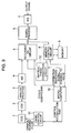
- Fig. 1 is a schematic block diagram of an imaging apparatus according to a first embodiment of the invention.
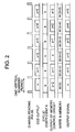
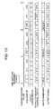
- Fig. 2 is a timing chart showing the operation timing of the imaging apparatus according to the first embodiment in the normal operation.
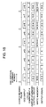
- Fig. 3 is a timing chart showing the operation timing of the imaging apparatus according to the first embodiment in the 2n-times accumulation sensitivity increase operation.
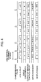
- Fig. 4 is a timing chart showing the operation timing of the imaging apparatus according to the first embodiment when the normal operation is changed to the 2n-times accumulation sensitivity increase operation.
- Fig. 5 is a timing chart showing the operation timing of the imaging apparatus according to the first embodiment when the 2m-times accumulation sensitivity increase operation is changed to the 2n-times accumulation sensitivity increase operation.
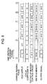
- Fig. 6 is a timing chart showing the operation timing of the imaging apparatus according to the first embodiment when the 2n-times accumulation sensitivity increase operation is changed to the normal operation.
- Fig. 7 is a timing chart showing the operation timing of the imaging apparatus according to the first embodiment when the 2n-times accumulation sensitivity increase operation is changed to the normal operation.
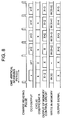
- Fig. 8 is a timing chart showing the operation timing of the imaging apparatus according to the first embodiment when the 2n-times accumulation sensitivity increase operation is changed to the normal operation.
- Fig. 9 is a block diagram showing a modification of the imaging apparatus according to the first embodiment.
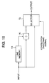
- Fig. 10 is a schematic block diagram showing a vertical-phase correction circuit of the imaging apparatus shown in Fig. 9.
- Fig. 11 is a timing chart showing the operation timing of the imaging apparatus shown in Fig. 9 when the 2n-times accumulation sensitivity increase operation is changed to the normal operation.
- Fig. 12 is a timing chart showing the operation timing of the imaging apparatus according to the first embodiment when the 2n-times accumulation sensitivity increase operation is changed to the normal operation.
- Fig. 13 is a timing chart showing the operation timing of the imaging apparatus according to the first embodiment in the (2n+1)-times accumulation sensitivity increase operation.
- Fig. 14 is a schematic block diagram of an imaging apparatus according to a second embodiment of the invention.
- Fig. 15 is a timing chart showing the operation timing of the imaging apparatus according to the second embodiment in the normal operation.
- Fig. 16 is a timing chart showing the operation timing of the imaging apparatus according to the second embodiment in the 2n-times accumulation sensitivity increase operation.
- Fig. 17 is a timing chart showing the operation timing of the imaging apparatus according to the second embodiment when the normal operation is changed to the 2n-times accumulation sensitivity increase operation.
- Fig. 18 is a timing chart showing the operation timing of the imaging apparatus according to the second embodiment when the 2m-times accumulation sensitivity increase operation is changed to the 2n-times accumulation sensitivity increase operation.
- Fig. 19 is a timing chart showing the operation timing of the imaging apparatus according to the second embodiment when the 2-times accumulation sensitivity increase operation is changed to the normal operation.
- Fig. 20 is a timing chart showing the operation timing of the imaging apparatus according to the second embodiment when the 2n-times accumulation sensitivity increase operation is changed to the normal operation.
- Fig. 21 is a timing chart showing the operation timing of the imaging apparatus according to the second embodiment when the 2n-times accumulation sensitivity increase operation is changed to the normal operation.
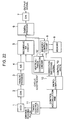
- Fig. 22 is a block diagram showing a modification of the imaging apparatus according to the second embodiment.
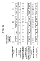
- Fig. 23 is a timing chart showing the operation timing of the imaging apparatus shown in Fig. 22 when the 2n-times accumulation sensitivity increase operation is changed to the normal operation.
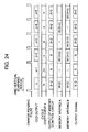
- Fig. 24 is a timing chart showing the operation timing of the imaging apparatus according to the second embodiment when the 2n-times accumulation sensitivity increase operation is changed to the normal operation.
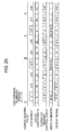
- Fig. 25 is a timing chart showing the operation timing of the imaging apparatus according to the second embodiment in the (2n+1)-times accumulation sensitivity increase operation.
- Fig. 26 is a schematic block diagram of an imaging apparatus according to a third embodiment of the invention.
- Fig. 27 is a timing chart showing the operation timing of the imaging apparatus according to the third embodiment in the normal operation.
- Fig. 28 is a timing chart showing the operation timing of the imaging apparatus according to the third embodiment in the 2n-times accumulation sensitivity increase operation.
- Fig. 29 is a timing chart showing the operation timing of the imaging apparatus according to the third embodiment when the normal operation is changed to the 2n-times accumulation sensitivity increase operation.
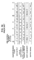
- Fig. 30 is a timing chart showing the operation timing of the imaging apparatus according to the third embodiment when the 2m-times accumulation sensitivity increase operation is changed to the 2n-times accumulation sensitivity increase operation.
- Fig. 31 is a timing chart showing the operation timing of the imaging apparatus according to the third embodiment when the 2n-times accumulation sensitivity increase operation is changed to the normal operation.
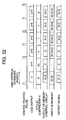
- Fig. 32 is a timing chart showing the operation timing of the imaging apparatus according to the third embodiment when the 2n-times accumulation sensitivity increase operation is changed to the normal operation.
- Fig. 33 is a timing chart showing the operation timing of the imaging apparatus according to the third embodiment when the 2n-times accumulation sensitivity increase operation is changed to the normal operation.
- Fig. 34 is a block diagram showing a modification of the imaging apparatus according to the third embodiment.
- Fig. 35 is a timing chart showing the operation timing of the imaging apparatus shown in Fig. 34 when the 2n-times accumulation sensitivity increase operation is changed to the normal operation.
- Fig. 36 is a timing chart showing the operation timing of the imaging apparatus according to the third embodiment when the 2n-times accumulation sensitivity increase operation is changed to the normal operation.
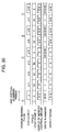
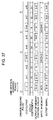
- Fig. 37 is a timing chart showing the operation timing of the imaging apparatus according to the third embodiment in the (2n+1)-times accumulation sensitivity increase operation.
- Fig. 38 is a schematic block diagram of a conventional imaging apparatus.
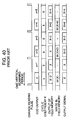
- Fig. 39 is a timing chart showing the operation timing of the conventional imaging apparatus in the normal operation.
- Fig. 40 is a timing chart showing the operation timing of the conventional imaging apparatus in the 2n-times accumulation sensitivity increase operation.
- Fig. 1 is a block diagram showing the schematic construction of the imaging apparatus according to the first embodiment of the invention.
- the imaging apparatus shown in Fig. 1 includes: a CCD 1 (the imaging means) for converting a light image into an electrical image signal; a CDS 2 for sampling the electrical image signal; an analog process circuit 3 for performing an analog signal process to the sampled image signal; an A/D (analog/digital conversion) circuit 4 for converting the analog-signal processed image signal into a digital signal; a recursive NR circuit 5 (the recursive noise reduction means) for performing a recursive filtering process to the digital image signal in the time-axis direction to reduce the noise component of this image signal; a digital process circuit 6 for performing a necessary signal process to the recursive-filtering processed image signal, a D/A (digital/analog conversion) circuit 7 for converting the necessary-signal processed image signal into an analog signal; a memory 9 (the storage means) for storing an output signal of the recursive NR circuit 5 for one frame period or more; a memory control circuit 8 (the memory control means) for controlling the
- the output signal of the recursive NR circuit 5, under the control of the memory control circuit 8, is supplied to the memory 9, delayed by two vertical scanning periods, and then fed back to the recursive NR circuit 5 as a cyclic signal.
- the microcomputer 10 controls the cyclic coefficient input to the recursive NR circuit 5, and controls the memory control circuit 8 to write to and read from the memory 9.
- the CCD 1 is controlled by a charge reading pulse from the timing control circuit 11.
- the accumulation sensitivity increase of the CCD 1 is performed when the microcomputer 10 controls the accumulation time input to the timing control circuit 11.
- the timing control circuit 11 supplies the charge reading pulse to the CCD 1 every vertical scanning period, and the CCD 1 outputs the image signal.
- the cyclic coefficient K which is input from the microcomputer 10 to the recursive NR circuit 5 is set to be k.
- the recursive NR circuit 5 performs the arithmetic operation using the image signal x and an output signal X-2 of the memory control circuit 8 to output the result as an output signal X.
- the output signal X is written to the memory 9.
- the cyclic coefficient K which is input from the microcomputer 10 to the recursive NR circuit 5 is similarly set to be k.
- the recursive NR circuit 5 performs the arithmetic operation using the image signal x+1 and an output signal X-1 of the memory control circuit 8 to output the result as an output signal X+1.
- the output signal X+1 is written to the memory 9.
- the timing control circuit 11 supplies the charge reading pulse to the CCD 1 every two vertical scanning periods, and the CCD 1 accumulates charges for two vertical scanning periods, and outputs the accumulated charges as the image signal.
- the cyclic coefficient K which is input from the microcomputer 10 to the recursive NR circuit 5 is set to be k.
- the recursive NR circuit 5 performs the arithmetic operation using the image signal x and an output signal X-2 of the memory control circuit 8 to output the result as an output signal X.
- the output signal X is written to the memory 9.
- the timing control circuit 11 supplies no charge reading pulse to the CCD 1, and hence the CCD 1 outputs no image signal.
- the cyclic coefficient K which is input from the microcomputer 10 to the recursive NR circuit 5 is set to be "0".
- an output signal X of the memory control circuit 8 is output as the output signal of the recursive NR circuit 5 as it is.
- the output signal X is not written to the memory 9.
- the signal stored in the memory 9 is used as the cyclic signal to the recursive NR circuit 5.
- the recursive NR process is performed using the signals in both fields of the interlaced signal without reducing the vertical resolution to perform the noise reduction.
- the recursive NR circuit 5 can be normally operated, and the cyclic coefficient can be simply controlled.
- the CCD 1 when the normal operation is changed to the 2-times accumulation sensitivity increase operation, the CCD 1 performs the normal operation until the timing of an image signal x+2, and then performs the 2-times accumulation sensitivity increase operation.
- the cyclic coefficient K is always set to be k until the timing of the image signal x+2, and the writing to the memory 9 is performed every vertical scanning period.
- the 2-times accumulation sensitivity increase operation begins at the timing of an image signal x+3.
- the image signal X+2 (the output signal of the memory control circuit 8) in the normal operation and the image signal x+4 in the 2-times accumulation sensitivity increase operation are supplied to the recursive NR circuit 5.
- the recursive NR circuit 5 performs the arithmetic operation using two kinds of signals with different amplitudes, and thus cannot properly operate. Consequently, the recursive NR circuit 5 outputs a signal with uncomfortable feeling.
- the cyclic coefficient K is set to be "1" so that the image signal x+4 from the CCD 1 is output from the recursive NR circuit 5 as it is.
- the cyclic coefficient K after 2n vertical scanning periods from this change of operation is set to be "1".
- the cyclic coefficient K is set to be k only during the vertical scanning period in which the image signal is output from the CCD 1.
- the cyclic coefficient K is set to be "0" so that the output signal of the memory control circuit 8 is output as the output signal of the recursive NR circuit 5 as it is, and the writing to the memory 9 is not performed.
- the 2-times accumulation sensitivity increase operation is performed from the timing of an image signal x+5.
- the image signal X+4 in the 4-times accumulation sensitivity increase operation and the image signal x+6 in the 2-times accumulation sensitivity increase operation are supplied to the recursive NR circuit 5.
- the recursive NR circuit 5 cannot correctly operate since it performs the arithmetic operation using the two signals with different amplitudes. Consequently, a signal with uncomfortable feeling is output from the recursive NR circuit 5.
- the cyclic coefficient K is set to be "1" so that the image signal x+6 from the CCD 1 is output from the recursive NR circuit 5 as it is, and the output signal X+6 of the recursive NR circuit 5 is written to the memory 9.
- the cyclic coefficient K after 2n vertical scanning periods from this change is set to be "1". Therefore, it is possible to prevent the recursive NR circuit 5 from the erroneous operation. Further, it is possible to change the 2m-times accumulation sensitivity increase operation is changed to the 2n-times accumulation sensitivity increase operation without any uncomfortable feeling.
- the cyclic coefficient K is set to be k only during the vertical scanning period in which the image signal is output from the CCD 1.
- the cyclic coefficient K is set to be "0" so that the output signal of the memory control circuit 8 is output from the recursive NR circuit 5 as it is, and the writing to the memory 9 is not performed.
- the normal operation begins from the timing of an image signal x+3. At the timing of the image signal x+3, an output signal X+1 of the memory control circuit 8 is to be essentially supplied to the recursive NR circuit 5.
- the recursive NR circuit 5 performs the arithmetic operation using the improper signal, and hence cannot properly operate. Consequently, a signal with uncomfortable feeling is output from the recursive NR circuit 5.
- the cyclic coefficient K is set to be "1" so that the image signal x+3 from the CCD 1 is output from the recursive NR circuit 5 as it is, and the output signal X+3 of the recursive NR circuit 5 is written to the memory 9.
- the cyclic coefficient K after one vertical scanning period from this change is controlled to be "1".
- a signal X+3 written to the memory 9 is a image signal x+3 itself output from the CCD 1. Also, a signal X+4 written to the memory 9 is a signal the noise component of which has been reduced in the recursive NR circuit 5. Therefore, a signal with uncomfortable feeling occurs between the fields of the interlaced signal.
- the cyclic coefficient K is set to be "1" so that the image signals x+3 and x+4 from the CCD 1 are output from the recursive NR circuit 5.
- the cyclic coefficient K in the two vertical scanning periods after one vertical scanning period from this change is controlled to be "1".
- the normal operation begins from the timing of an image signal x+3. Since there is no cyclic signal corresponding to the timing of the image signal x+3, an image signal X+2 of the opposite field, which has just been written to the memory 9, is output from the memory control circuit 8.
- the noise reduction can be performed intermittently without any uncomfortable feeling.
- the opposite-field signal is output as the cyclic data in one vertical scanning period from this change.
- FIG. 9 the same blocks corresponding to those of the imaging apparatus shown in Fig. 1 are identified by the same reference numerals, and their constructions and operations will not be described.
- the imaging apparatus shown in Fig. 9 includes a vertical-phase correction circuit 12 (the vertical-phase correction means) for performing a vertical-phase correction process in which 1/2 line spatial phase shift is corrected to an image signal of the opposite field read out by the memory control circuit 8, to supply the vertical-phase-correction processed image signal to the recursive NR circuit 5.
- a vertical-phase correction circuit 12 the vertical-phase correction means for performing a vertical-phase correction process in which 1/2 line spatial phase shift is corrected to an image signal of the opposite field read out by the memory control circuit 8, to supply the vertical-phase-correction processed image signal to the recursive NR circuit 5.
- the vertical-phase correction circuit 12 includes, as shown in Fig. 10, a line memory 13 for delaying by one horizontal period the image signal read out by the memory control circuit 8; an adder 14 for adding the image signal read out by the memory control circuit 8 and the one-horizontal-period delayed signal from the line memory 13 and dividing the sum by "2"; and a selector 15 for selecting one of an output of the adder 14 and the image signal read out by the memory control circuit 8 in accordance with a correction switching signal from the microcomputer 10.
- the 2-times accumulation sensitivity increase operation is change to the normal operation, the CCD 1 performs the 2-times accumulation sensitivity increase operation until the timing of an image signal x+2, and then performs the normal operation.
- the normal operation begins from the timing of an image signal x+3. Since there is no cyclic signal corresponding to the timing of the image signal x+3, an signal X+2 of the opposite field which has just been written to the memory 9 is output from the memory control circuit 8.
- the signal X+2 is the opposite-field signal of the interlaced signal, it is deviated by 1/2 line in the vertical phase from the image signal x+3.
- the correction switching signal is changed at the timing of the image signal x+3, a 1/2-line corrected signal X+2' is produced from the vertical-phase correction circuit 12.
- the 1/2-line vertical-phase deviation can be corrected with maintaining the cyclic coefficient K to be k.
- the noise reduction can be intermittently performed without any uncomfortable feeling.
- the CCD 1 performs the 2-times accumulation sensitivity increase operation until the timing of an image signal x+2, and then performs the normal operation.
- the normal operation begins from the timing of an image signal x+3. At the timing of the image signal x+3, since a signal X+2 is previously written to the memory, the recursive NR process is performed to the image signals x+3 and X+2.
- the noise reduction can be intermittently made without any uncomfortable feeling with maintaining the cyclic coefficient K to be k.
- the charge reading pulse is output from the timing control circuit 11 to the CCD 1 every three vertical scanning periods.
- the CCD 1 accumulates charges corresponding to three vertical scanning periods to output the accumulated charges as an image signal.
- the cyclic coefficient K which is input from the microcomputer 10 to the recursive NR circuit 5 is set to be k.
- the recursive NR circuit 5 performs the arithmetic operation using the image signal x and an output signal X-6 of the memory control circuit 8 which is the most adjacent signal with the same vertical phase in the interlaced signal to produce an output signal X.
- the output signal X is written to the memory 9.
- the charge reading pulse is not output from the timing control circuit 11 to the CCD 1, so that the CCD 1 outputs no image signal.
- the cyclic coefficient K which is input from the microcomputer 10 to the recursive NR circuit 5 is set to be "0". Consequently, the output signals X-3 and X of the memory control circuit 8 are output as the output signals of the recursive NR circuit 5 as they are. At this time, the output signals are not written to the memory 9.
- the image signal x+3 is output from the CCD 1.
- the recursive NR circuit 5 performs the arithmetic operation using the image signal x+3 and an output signal X-3 of the memory control circuit 8 which is the most adjacent signal with the same vertical phase in the interlaced signal to produce an output signal X+3.
- the output signal X+3 is written to the memory 9.
- the output signal can be prevented from its vertical resolution deterioration, and the recursive NR process can be made using the interlaced signals with the same vertical phase.
- Fig. 14 is a block diagram showing the schematic structure of the imaging apparatus.
- the same blocks as those of the imaging apparatus shown in Fig. 1 are identified by the same reference numerals, and their constructions and operations will not be described.
- the imaging apparatus shown in Fig. 14 is different from the imaging apparatus shown in Fig. 1 in that the output signal of the recursive NR circuit 5 is supplied not to the digital process circuit 6, but to the memory control circuit 8, and the output signal of the memory control circuit 8 is supplied to the digital process circuit 6.
- the recursive NR circuit 5 performs the recursive filtering process to the image signal in the time-axis direction, and the memory control circuit 8 controls the memory 9 to write the processed image signal.
- the memory control signal 8 then controls the memory 9 to read out that signal in such a manner as to delay it by two vertical scanning periods.
- the read-out signal is supplied as a cyclic signal to the recursive NR circuit 5 and also supplied to the digital process circuit 6 where the necessary signal process is performed.
- the output signal of the digital process circuit is converted into an analog signal by the D/A circuit 7.
- the cyclic coefficient K which is input from the microcomputer 10 to the recursive NR circuit 5 is set to be k.
- the recursive NR circuit 5 performs the arithmetic operation using the image signal x and an output signal X-2 of the memory control circuit 8.
- An output signal X of the recursive NR circuit 5 is written to the memory 9.
- the output signal X-2 of the memory control circuit 8 is output to the outside through the digital process circuit 6 and the D/A circuit 7.
- the cyclic coefficient K which is input from the microcomputer 10 to the recursive NR circuit 5 is set to be k.
- the recursive NR circuit 5 performs the arithmetic operation using the image signal x+1 and an output signal X-1 of the memory control circuit 8.
- An output signal X+1 of the recursive NR circuit 5 is written to the memory 9.
- the output signal X-1 of the memory control circuit 8 is output to the outside through the digital process circuit 6 and the D/A circuit 7.
- the cyclic coefficient K which is input from the microcomputer 10 to the recursive NR circuit 5 is set to be k.
- the recursive NR circuit 5 performs the arithmetic operation using the image signal x and an output signal X-2 of the memory control circuit 8.
- An output signal X of the recursive NR circuit 5 is written to the memory 9.
- the output signal X-2 of the memory control circuit 8 is output to the outside through the digital process circuit 6 and the D/A circuit 7.
- the cyclic coefficient K may be an arbitrary value. However, if the cyclic coefficient K is set to be k, it is not necessary to switch the values of the cyclic coefficient K according to the timing, and thus the cyclic coefficient can be simply controlled.
- the signal written to the memory 9 is used as the cyclic signal to the recursive NR circuit 5.
- the recursive NR process is performed using the both-fields signals of the interlaced signal without deteriorating the vertical resolution to perform the noise reduction.
- the accumulation time of CCD 1 is changed to perform the 2n-times accumulation sensitivity increase operation, the recursive NR circuit 5 can be properly operated and the cyclic coefficient can be simply controlled.
- the 2-times accumulation sensitivity increase operation begins from the timing of an image signal x+3. At the timing of an image signal x+4, an image signal X+2 in the normal operation and the image signal x+4 in the 2-times accumulation sensitivity increase operation are supplied to the recursive NR circuit 5.
- the recursive NR circuit 5 cannot properly operate because it carries out the arithmetic operation using the two signals with different amplitudes. Consequently, a signal with uncomfortable feeling is output from the recursive NR circuit 5.
- the cyclic coefficient K is set to be "1" so that the image signal from the CCD 1 is output as it is.
- the cyclic coefficient K after 2n vertical scanning periods from this change is set to be "1".
- the 2-times accumulation sensitivity increase operation begins from the timing of an image signal x+5. At the timing of an image signal x+6, an image signal X+4 in the 4-times accumulation sensitivity increase operation and the image signal x+6 in the 2-times accumulation sensitivity increase operation are supplied to the recursive NR circuit 5.
- the recursive NR circuit 5 cannot properly operate because it performs the arithmetic operation using the two signals with different amplitudes. Consequently, a signal with uncomfortable feeling is output from the recursive NR circuit 5.
- the cyclic coefficient K is set to be "1" so that the image signal from the CCD 1 is outputted as it is.
- the cyclic coefficient K after 2n vertical scanning periods from this change is set to be "1".
- the normal operation begins from the timing of an image signal x+3.
- a signal X+1 should be essentially supplied to the recursive NR circuit 5.
- the signal X+1 is not a correct one which has just been written to the memory 9. Therefore, the recursive NR circuit 5 cannot properly operate because it performs the arithmetic operation using the incorrect signal. Consequently, a signal with uncomfortable feeling is output from the recursive NR circuit 5.
- the cyclic coefficient K is set to be "1" so that the image signal from the CCD is output as it is. Therefore, since the output signal of the memory control circuit 8 is output to the outside as the output signal, the signal X+2 is output from the memory 9.
- the cyclic coefficient K after one vertical scanning period from this change is set to be "1".
- a signal X+3 written to the memory 9 is an image signal x+3 from the CCD 1, and an signal X+4 is a noise-reduced signal from the recursive NR circuit 5.
- the signal between the fields of the interlaced signal is a signal with uncomfortable feeling.
- the cyclic coefficient K is set to be "1" so that the image signals x+3 and x+4 from the CCD 1 are outputted as they are.
- the cyclic coefficient K in two vertical scanning periods after one vertical scanning period from this change is set to be "1".
- the normal operation begins from the timing of an image signal x+3. Since there is no cyclic signal corresponding to the timing of the image signal x+3, an signal X+2 of the opposite field which has just been written to the memory 9 is output from the memory control circuit 8.
- the cyclic coefficient K is maintained to be k, and the noise reduction can be intermittently made without any uncomfortable feeling.
- the opposite-field signal is output as the cyclic data in one vertical scanning period after one vertical scanning period from this change.
- FIG. 22 the blocks corresponding to those of the imaging apparatus shown in Fig. 1 are identified by the same reference numerals, and their constructions and operations will not be described.
- the imaging apparatus shown in Fig. 22 includes the vertical-phase correction circuit 12 that performs the vertical-phase correction process in which the 1/2-line spatial phase shift is corrected to the image signal of the opposite field read out by the memory control circuit 8, to supply the vertical-phase-correction processed image signal to the recursive NR circuit 5.
- the vertical-phase correction circuit 12 includes: the memory 13 for delaying by one horizontal scanning period the image signal read out by the memory control circuit 8; the adder 14 for adding the image signal read out by the memory control circuit 8 and the image signal delayed by one horizontal scanning period by the line memory 13 and diving the sum by "2"; and the selector 15 for switching the output of the adder 14 and the image signal read out by the memory control circuit 8 in accordance with the correction switching signal from the microcomputer 10.
- the normal operation begins from the timing of an image signal x+3. Since there is no cyclic signal corresponding to the timing of the image signal x+3, a signal X+2 of the opposite field which has just been written to the memory 9 is output from the memory control circuit 8.
- the vertical phase of the signal X+2 deviates by 1/2 line from the image signal x+3.
- a 1/2-line corrected signal X+2' is output from the vertical-phase correction circuit 12 by changing the correction switching signal at the timing of the image signal x+3. Consequently, at the timing of the image signal x+3, the cyclic coefficient K is maintained to be k and the 1/2-line vertical phase shift is corrected, so that the noise reduction can be performed without any uncomfortable feeling.
- the opposite-field signal is output as the cyclic data in one vertical scanning period after one vertical scanning period from this change to correct the 1/2-line vertical phase shift.
- the recursive NR circuit 5 can be prevented from the erroneous operation, and the change from the 2n-times accumulation sensitivity increase operation to the normal operation can be made without any uncomfortable feeling.
- the memory writing A and the memory writing B which respectively correspond to the two fields are always controlled so that the field signals are written to the two memories.
- the normal operation begins from the timing of an image signal x+3.
- the recursive NR process is performed using the image signal x+3 and an signal X+2 since the signal X+2 is previously written to the memory 9.
- the cyclic coefficient K is maintained to be k and the noise reduction can be intermittently made without any uncomfortable feeling.
- the signals are written to both memories corresponding to the two fields during the accumulation sensitivity increase operation.
- the cyclic coefficient K which is input from the microcomputer 10 to the recursive NR circuit 5 is set to be k.
- the recursive NR circuit 5 performs the arithmetic operation using the image signal x and an output signal X-6 of the memory control circuit 8 which is the most adjacent signal with the same vertical phase in the interlaced signal, to produce an output signal X.
- the output signal X of the memory control circuit 8 is output to the outside through the digital process circuit 6 and the D/A circuit 7.
- the output signals X-3 and X of the memory control circuit 8 are output to the outside as they are.
- the vertical resolution of the output signal can be prevented from deterioration, and the recursive NR process can be performed using the interlaced signals with the same vertical phase.
- Fig. 26 is a schematic block diagram of the imaging apparatus according to the third embodiment.
- the same blocks as those of the imaging apparatus shown in Fig. 1 are identified by the same reference numerals, and their constructions and operations will not be described.
- the imaging apparatus shown in Fig. 26 is different from the imaging apparatus shown in Fig. 1 in that the output signal of the recursive NR circuit 5 is supplied not to the digital process circuit 6, but to the memory control circuit 8, and the output signal of the memory control circuit 8 is supplied as the first output signal to the recursive NR circuit 5 and as the second output signal to the digital process circuit 6.
- the recursive NR circuit 5 performs the recursive filtering process to image signal in the time-axis direction, and the recursive-filtering processed signal is supplied to the memory control circuit 8.
- the memory control circuit 8 writes the recursive-filtering processed image signal to the memory 9.
- the memory control circuit 8 reads out from the memory 9 the image signal, which is delayed by two vertical scanning periods, as the first output signal to supply it to the recursive NR circuit 5 as the cyclic signal.
- the memory control circuit 8 also supplies the read-out signal from the memory 9 as the second output signal to the digital process circuit 6.
- the second output signal is converted into an analog signal by the D/A circuit 7, and then output to the outside.
- the cyclic coefficient K which is input from the microcomputer 10 to the recursive NR circuit 5 is set to be k.
- the recursive NR circuit 5 performs the arithmetic operation using the image signal x and the first output signal X-2 of the memory control circuit 8.
- An output signal X of the recursive NR circuit 5 is written to the memory 9.
- An image signal X-1 stored in memory 9 and delayed by one vertical scanning period is output from the memory control circuit 8 as the second output signal.
- the cyclic coefficient K which is input from the microcomputer 10 to the recursive NR circuit 5 is set to be k.
- the recursive NR circuit 5 performs the arithmetic operation using the image signal x+1 and the first output signal X-1 of the memory control circuit 8.
- the memory control circuit 8 writes the output signal X+1 of the recursive NR circuit 5 to the memory 9, and reads out the signal X stored to the memory 9 to output the read out signal X to the digital process circuit 6 as the second output signal.
- the cyclic coefficient K which is input from the microcomputer 10 to the recursive NR circuit 5 is set to be k.
- the arithmetic process is performed using the image signal x and the first output signal X-2 of the memory control circuit 8.
- the memory control circuit 8 controls writes the output signal X of the recursive NR circuit 5 to the memory 9 and reads out the signal X-2 stored in the memory 9 to output the read-out signal X-2 to the digital process circuit 6 as the second output signal.
- the output signal of the recursive NR circuit 5 is not written to the memory 9, and the first output signal of the memory control circuit 8 may be the signal of arbitrary timing.
- the image signal X-1 is output as the first output signal, the accumulation sensitivity increasing operation can be controlled in the same way as the normal operation, and the first output signal can be simply controlled.
- the cyclic coefficient K may be the arbitrary value
- the cyclic coefficient K is set to be k. Therefore, there is no need to switch the cyclic coefficients according to the timing, and the cyclic coefficient can be simply controlled.
- the signal stored in the memory 9 is used as the cyclic signal to the recursive NR circuit 5.
- the noise reduction by the recursive NR process can be made without deteriorating the vertical resolution by use of the both-fields signals of the interlaced signal.
- the recursive NR circuit 5 can be properly operated, and the cyclic coefficient and the memory output can be simply controlled.
- the 2-times accumulation sensitivity increase operation begins from the timing of an image signal x+3. At the timing of an image signal x+4, an image signal X+2 in the normal operation and the image signal x+4 in the 2-times accumulation sensitivity increase operation are supplied to the recursive NR circuit 5.
- the recursive NR circuit 5 cannot properly operate because it performs the arithmetic operation using the two signals with different amplitudes. Consequently, a signal with uncomfortable feeling is output from the recursive NR circuit 5.
- the cyclic coefficient K is set to be "1" so that the image signal from the CCD 1 can be output.
- the cyclic coefficient after 2n vertical scanning periods from this change is set to be "1".
- the recursive NR circuit 5 can be prevented from the erroneous operation, and the change from the normal operation to the 2n-times accumulation sensitivity increase operation can be made without any uncomfortable feeling.
- the 2-times accumulation sensitivity increase operation begins from the timing of an image signal x+5. At the timing of an image signal x+6, an image signal X+4 in the 4-times accumulation sensitivity increase operation and an image signal x+6 in the 2-times accumulation sensitivity increase operation are supplied to the recursive NR circuit 5.
- the recursive NR circuit 5 cannot properly operate because it performs the arithmetic operation using the two signals with different amplitudes. Consequently, a signal with uncomfortable feeling is output from the recursive NR circuit 5.
- the cyclic coefficient K is set to be "1" so that the image signal from the CCD 1 is output.
- the cyclic coefficient after 2n vertical scanning periods from this change is set to be "1".
- the recursive NR circuit 5 can be prevented from the erroneous operation, and the change from the 2m-times accumulation sensitivity increase operation to the 2n-times accumulation sensitivity increase operation can be made without any uncomfortable feeling.
- the normal operation begins from the timing of an image signal x+3.
- an image signal X+1 should be essentially supplied to the recursive NR circuit 5.
- the image signal X+1 is not the correct signal which has just been written to the memory 9. Therefore, the recursive NR circuit 5 cannot properly operate because it performs the arithmetic operation using the incorrect signal, so that a signal with uncomfortable feeling is output from the recursive NR circuit 5.
- the cyclic coefficient K is set to be "1" so that the image signal from the CCD 1 is output.
- the memory control circuit 8 reads out the signal X+2 from the memory 9 in order to output the signal X+2 as the second output signal.
- the cyclic coefficient K in one vertical scanning period after one vertical scanning period from this change is set to be "1".
- a signal X+3 written to the memory 9 is an image signal x+3 from the CCD 1, and an image signal X+4 is a signal the noise component of which is reduced in the recursive NR circuit 5.
- the signal between the fields of the interlaced signal has uncomfortable feeling.
- the cyclic coefficient K is set to be "1" so that the image signal from the CCD 1 is output.
- the cyclic coefficient K is set to be "1" at the timings of the image signals in two vertical scanning periods after one vertical scanning period from the change of operation.
- the normal operation begins from the timing of an image signal x+3. Since there is no cyclic signal corresponding to the timing of the image signal x+3, a signal X+2 of the opposite field which has just been written to the memory 9 is output from the memory control circuit 8.
- the cyclic coefficient K is maintained to be k, and the noise reduction can be performed intermittently without any uncomfortable feeling.
- the opposite-field signal is output as the cyclic data in one vertical scanning period after one vertical scanning period from this change.
- the recursive NR circuit 5 can be prevented from the erroneous operation, and the change from 2n-times accumulation sensitivity increase operation to the normal operation can be made without any uncomfortable feeling.
- FIG. 34 Another imaging apparatus according to this embodiment will be described with reference to Fig. 34.
- the same blocks as those of the imaging apparatus shown in Fig. 1 are identified by the same reference numerals, and their constructions and operations will not be described.
- the imaging apparatus shown in Fig. 34 includes the vertical-phase correction circuit 12 that performs the vertical-phase correction process in which the 1/2-line spatial phase shift is corrected to the image signal of the opposite field read out by the memory control circuit 8, to supply the vertical-phase-correction processed image signal to the recursive NR circuit 5.
- the vertical-phase correction circuit 12 includes: the memory 13 for delaying by one horizontal scanning period the image signal read out by the memory control circuit 8; the adder 14 for adding the image signal read out by the memory control circuit 8 and the image signal delayed by one horizontal scanning period by the line memory 13 and diving the sum by "2"; and the selector 15 for switching the output of the adder 14 and the image signal read out by the memory control circuit 8 in accordance with the correction switching signal from the microcomputer 10.
- the normal operation begins from the timing of an image signal x+3. Since there is no cyclic signal corresponding to the timing of the image signal x+3, a signal X+2 of the opposite field which has just been written to the memory 9 is output from the memory control circuit 8.
- the vertical phase of the signal X+2 deviates by 1/2 line from the image signal x+3.
- a 1/2-line corrected signal X+2' is output from the vertical-phase correction circuit 12 by changing the correction switching signal at the timing of the image signal x+3. Consequently, at the timing of the image signal x+3, the cyclic coefficient K is maintained to be k and the 1/2-line vertical phase shift is corrected, so that the noise reduction can be performed without any uncomfortable feeling.
- the opposite-field signal is output as the cyclic data in one vertical scanning period after one vertical scanning period from this change to correct the 1/2-line vertical phase shift.
- the recursive NR circuit 5 can be prevented from the erroneous operation, and the change from the 2n-times accumulation sensitivity increase operation to the normal operation can be made without any uncomfortable feeling.
- the memory writing A and the memory writing B which respectively correspond to the two fields are always controlled so that the field signals are written to the two memories.
- the normal operation begins from the timing of an image signal x+3. Since a signal X+2 is previously written to the memory 9 at this timing, the recursive NR process is performed using the image signal x+3 and the signal X+2. Thereby, at the timing of the image signal x+3, the cyclic coefficient K is maintained to be k and the noise reduction can be intermittently made without any uncomfortable feeling.
- the signals are written to both memories corresponding to the two fields during the accumulation sensitivity increase operation.
- the cyclic coefficient K which is input from the microcomputer 10 to the recursive NR circuit 5 is set to be k.
- the memory control circuit 8 outputs as the first output signal a signal X-6 which is the most adjacent signal with the same vertical phase as the image signal x in the interlaced signal.
- the recursive NR circuit 5 performs the arithmetic operation using the image signal x and the first output signal X-6.
- the memory control circuit 8 writes the output signal X of the recursive NR circuit 5 to the memory 9 and outputs the signal X-6 to the digital process circuit 6 as the second output signal.
- the memory control circuit 8 outputs the output signals X-3 and X as the second output signal, respectively.
- the vertical resolution of the output signal can be prevented from deterioration, and the recursive NR process can be performed using the interlaced signals with the same vertical phase.
- the analog process circuit 3, the recursive NR circuit 5 and the digital process circuit 6 are connected in this order.
- the same effect can be achieved even though the order of the connection of these circuits is changed as in the connection of the recursive NR circuit 5, the analog process circuit 3 and the digital process circuit 6, the connection of the analog process circuit 3, the digital process circuit 6 and the recursive NR circuit 5, or the replacement between the analog process circuit 3 and the digital process circuit 6.
- the memory control circuit 8 is used to control the memory 9 to write/read.
- the memory 9 directly performs the write/read operation without using the memory control circuit 8.
Landscapes
- Engineering & Computer Science (AREA)
- Multimedia (AREA)
- Signal Processing (AREA)
- Transforming Light Signals Into Electric Signals (AREA)
- Studio Devices (AREA)
- Picture Signal Circuits (AREA)
Abstract
Description
- The present invention generally relates to an imaging apparatus, and particularly to an imaging apparatus having a picture memory function to simultaneously achieve a recursive noise reduction circuit (hereinafter, referred to simply as "recursive NR circuit"), and long time accumulation (accumulation sensitivity increase) of CCD.
- Conventionally, such a recursive NR circuit has been used in a video system in order to reduce noise using a memory. However, semiconductor memories have recently developed to have large capacity at low cost, so that a memory and a recursive NR circuit have been incorporated in an imaging apparatus. Thus, the imaging apparatus have had the combination with various functions using memories.
- For example, JP-A-5-236312 describes various functions using a recursive NR circuit and a memory system. Particularly, in the second noise reduction mode, the noise reduction effect is achieved by the recursive NR circuit and the accumulation sensitivity increase over 2-field periods.
- Such a conventional imaging apparatus will be described with reference to Fig. 38. Fig. 38 is a schematic block diagram of a conventional imaging apparatus.
- The imaging apparatus shown in Fig. 38 includes: a
CCD 101 for converting a light image into an electrical image signal; aCDS 102 for sampling the electrical image signal; an A/D circuit 103 for converting the sampled image signal into a digital signal; arecursive NR circuit 104 that performs the recursive filtering process to the digital image signal in the time-axis direction to reduce the noise component of the image signal; adigital process circuit 105 that performs the necessary signal process to the recursive-filtered image signal; a D/A circuit 106 that converts the processed image signal into an analog signal to be output; afield memory 107 for storing an output signal of therecursive NR circuit 104; a fieldmemory control circuit 108 for controlling thefield memory 107; and amicrocomputer 109 for controlling the whole imaging apparatus. - The field
memory control circuit 108 delays the output signal of therecursive NR circuit 104 by one vertical scanning period, and outputs this delayed signal to therecursive NR circuit 104 as a cyclic signal. - The
microcomputer 109 controls the cyclic coefficient of therecursive NR circuit 104, and controls the fieldmemory control circuit 108 to write to and read from thefield memory 107. - The
CCD 101 is controlled by a charge reading pulse from atiming control circuit 110. The accumulation sensitivity increase is achieved when themicrocomputer 109 controls the accumulation time that is input to thetiming control circuit 110. - Fig. 39 is a timing chart showing the operation timing of this imaging apparatus in the normal operation.
- As illustrated in Fig. 39, in the normal operation, the
timing control circuit 110 outputs the charge reading pulse to theCCD 101 every vertical scanning period, so that the image signal is output from theCCD 101. - When an image signal x is output from the
CCD 101, the cyclic coefficient K which is input from themicrocomputer 109 to therecursive NR circuit 104 is set to be k. Therecursive NR circuit 104 performs the arithmetic operation using the image signal x and an output signal X-2 of thefield memory 107 to output the result as an output signal X. The output signal X is written to thefield memory 107. - When an image signal x+1 is output from the
CCD 101, the cyclic coefficient K which is input from themicrocomputer 109 to therecursive NR circuit 104 is set to be "0". Consequently, the output signal X of thefield memory 107 is output from therecursive NR circuit 104 as the output signal X as it is. At this time, the output signal X of therecursive NR circuit 104 is not written to thefield memory 107. - Fig. 40 is a timing chart showing the operation timing of this imaging apparatus in a 2-times accumulation sensitivity increase operation.
- As illustrated in Fig. 40, when the accumulation sensitivity is increased twice, the
timing control circuit 110 outputs the charge reading pulse to theCCD 101 every two vertical scanning periods. Therefore, theCCD 101 accumulates charges for two vertical scanning periods, and outputs the accumulated charges as an image signal. - When an image signal x is output from the
CCD 101, the cyclic coefficient K which is input from themicrocomputer 109 to therecursive NR circuit 104 is set to be k. Therecursive NR circuit 104 performs the arithmetic operation using the image signal x and an output signal X-2 of thefield memory 107 to output the result as an output signal X. The output signal X is written to thefield memory 107. - When an image signal x+1 is output from the
CCD 101, thetiming control circuit 110 outputs no charge reading pulse, and hence theCCD 101 outputs no image signal. - Therefore, the cyclic coefficient K which is input from the
microcomputer 109 to therecursive NR circuit 104 is set to be "0" so that the output signal X of thefield memory 107 is output from therecursive NR circuit 104 as the output signal X as it is. In addition, the output signal X of therecursive NR circuit 104 is not written to thefield memory 107. - Thus, the accumulation sensitivity can be increased twice, and at the same time the recursive NR can be achieved. Both of the sensitivity increase and the noise reduction can be attained.
- In the above conventional imaging apparatus, however, the recursive NR is performed using the
filed memory 107, and the noise reduction operation by the recursive NR in the normal operation is performed by circulation of only one-field signal of the interlaced signal with the other-field signal not used. As a result, the vertical resolution is deteriorated. In addition, when the normal operation is changed to the accumulation sensitivity increase operation or when the accumulation sensitivity increase operation is changed to the normal operation, uncomfortable feeling occurs in the recursive NR operation. - It is an object of the invention to provide an imaging apparatus that has functions to use the both-fields signals of the interlaced signal for the recursive noise reduction in the normal operation, and to prevent the uncomfortable feeling in the recursive NR when the accumulation time of CCD (the accumulation sensitivity increase operation) is changed.
- In order to achieve the above object, an imaging apparatus according to the first aspect of the invention includes:
- imaging means for accumulating an image signal by an n-times long time accumulation (n is an integer of "1" or more);
- timing control means for controlling to read out the image signal stored in the imaging means according to the n-times long time accumulation;
- memory means for storing the image signal read out by the timing control means for one frame period or more;
- memory control means for controlling the memory means; and
- recursive noise reduction means for performing a noise reduction process on the basis of the image signal read out from the imaging means and the one-frame-period-or-more delayed image signal read out from the memory means to generate a noise-reduction processed image signal, wherein when the imaging means performs a 2n-times long time accumulation, in a vertical scanning period in which the image signal is output from the imaging means, the memory control means writes to the memory means the image signal generated by the recursive noise reduction means, and the recursive noise reduction means outputs the generated image signal as an output signal as it is; and
-
- This imaging apparatus may use the memory means such as a frame memory, and performs the recursive noise reduction process to the both-fields signal of the interlaced signal in the normal operation. Thereby, it is possible to reduce noise without deteriorating the vertical resolution. Further, even if the imaging means such as a CCD performs the 2n-times long time accumulation (or the accumulation sensitivity increase), it is possible to make the recursive noise reduction means operate properly.
- In an imaging apparatus according to the second aspect of the invention, when the long time accumulation in the imaging means changes from one-time to 2n-times, after 2n vertical scanning periods from this change, the recursive noise reduction means outputs the image signal from the imaging means as the output signal as it is, without performing the noise reduction process.
- In this imaging apparatus, even when the long time accumulation in the imaging means changes from one-time to 2n-times, after 2n vertical scanning periods from this change, the recursive noise reduction means outputs the image signal from the imaging means as the output signal as it is, without performing the noise reduction process. Thereby, it is possible to prevent the recursive noise reduction means from the erroneous operation. Further, it is possible to change the one-time accumulation sensitivity increase operation to the 2n-times accumulation sensitivity increase operation without any uncomfortable feeling.
- In an imaging apparatus according to the third aspect of the invention, when the long time accumulation in the imaging means changes from 2m-times (m is an integer of "1" or more, m≠n) to 2n-times, after 2n vertical scanning periods from this change, the recursive noise reduction means outputs the image signal from the imaging means as the output signal as it is, without performing the noise reduction process.
- In this imaging apparatus, even when the long time accumulation in the imaging means changes from 2m-times to 2n-times, after 2n vertical scanning periods from this change, the recursive noise reduction means outputs the image signal from the imaging means as the output signal as it is, without performing the noise reduction process. Thereby, it is possible to prevent the recursive noise reduction means from the erroneous operation. Further, it is possible to change from the 2m-times accumulation sensitivity increase operation to the 2n-times accumulation sensitivity increase operation without any uncomfortable feeling.
- In an imaging apparatus according to the fourth aspect of the invention, when the long time accumulation in the imaging means changes from 2n-times to one-time, in a vertical scanning period after one vertical scanning period from this change, the recursive noise reduction means outputs the image signal from the imaging means as the output signal as it is, without performing the noise reduction process.
- In this imaging apparatus, even when the long time accumulation in the imaging means changes from 2n-times to one-time, in a vertical scanning period after one vertical scanning period from this change, the recursive noise reduction means outputs the image signal from the imaging means as the output signal as it is, without performing the noise reduction process. Thereby, it is possible to prevent the recursive noise reduction means from the erroneous operation. Further, it is possible to change from the 2n-times accumulation sensitivity increase operation to the one-time accumulation sensitivity increase operation without any uncomfortable feeling.
- In an imaging apparatus according to the fifth aspect of the invention, when the long time accumulation in the imaging means changes from 2n-times to one-time, in two or more vertical scanning periods after one vertical scanning period from this change, the recursive noise reduction means outputs the image signal from the imaging means as the output signal as it is, without performing the noise reduction process.
- In this imaging apparatus, even when the long time accumulation in the imaging means changes from 2n-times to one-time, in two or more vertical scanning periods after one vertical scanning period from this change, the recursive noise reduction means outputs the image signal from the imaging means as the output signal as it is, without performing the noise reduction process. Thereby, it is possible to prevent the recursive noise reduction means from the uncomfortable feeling in operation. Further, it is possible to remove the uncomfortable feeling between the fields of the interlaced signal in the two vertical scanning periods.
- In an imaging apparatus according to the sixth aspect of the invention, when the long time accumulation in the imaging means changes from 2n-times to one-time, in a vertical scanning period after one vertical scanning period from this change, the memory control means reads out an image signal of an opposite field stored in the memory means, and makes the recursive noise reduction means perform the noise reduction process on the basis of the read-out image signal of the opposite field and the image signal from the imaging means.
- In this imaging apparatus, even when the long time accumulation in the imaging means changes from 2n-times to one-time, in a vertical scanning period after one vertical scanning period from this change, the memory control means reads out an image signal of an opposite field stored in the memory means, and makes the recursive noise reduction means perform the noise reduction process on the basis of the read-out image signal of the opposite field and the image signal from the imaging means. Thereby, by outputting the opposite-field signal as the cyclic data after one vertical scanning period from the change, it is possible to prevent the recursive noise reduction means from the erroneous operation, and to change from the 2n-times accumulation sensitivity increase operation to the one-time accumulation sensitivity increase operation without any uncomfortable feeling.
- In an imaging apparatus according to the seventh aspect of the invention, when the long time accumulation in the imaging means changes from 2n-times to one-time, in a vertical scanning period after one vertical scanning period from this change, the memory control means reads out an image signal of an opposite field stored in the memory means, makes vertical-phase correction means perform a vertical-phase correction process to correct the read-out image signal of the opposite field for 1/2 line spatial phase shift, and makes the recursive noise reduction means perform the noise reduction process on the basis of the vertical-phase-correction processed image signal and the image signal from the imaging means.
- In this imaging apparatus, even when even when the long time accumulation in the imaging means changes from 2n-times to one-time, in a vertical scanning period after one vertical scanning period from this change, the memory control means reads out an image signal of an opposite field stored in the memory means, makes vertical-phase correction means perform a vertical-phase correction process to correct the read-out image signal of the opposite field for 1/2 line spatial phase shift, and makes the recursive noise reduction means perform the noise reduction process on the basis of the vertical-phase-correction processed image signal and the image signal from the imaging means. Thereby, by outputting the opposite-field signal as the cyclic data after one vertical scanning period from the change to correct the 1/2 line vertical phase shift, it is possible to prevent the recursive noise reduction means from the erroneous operation, and to change from the 2n-times accumulation sensitivity increase operation to the one-time accumulation sensitivity increase operation without any uncomfortable feeling.
- An imaging apparatus according to the eighth aspect of the invention further comprises two of the memory means, wherein when the imaging means performs the long time accumulation, in a vertical scanning period in which the image signal is output from the imaging means, the memory control means writes the image signal generated by the recursive noise reduction means to each memory means.
- In this imaging apparatus, when the imaging means performs the long time accumulation, in a vertical scanning period in which the image signal is output from the imaging means, the memory control means writes the image signal generated by the recursive noise reduction means to each memory means. Thereby, it is possible to prevent the recursive noise reduction means from the erroneous operation. Further, it is possible to provide the imaging apparatus without any uncomfortable feeling.
- In an imaging apparatus according to the ninth aspect of the invention, when the imaging means performs a (2n+1)-times long time accumulation, in a vertical scanning period in which the image signal is output from the imaging means, the memory control means writes the image signal generated from the recursive noise reduction means to the memory means, and the recursive noise reduction means outputs the generated image signal as the output signal as it is; and
in a vertical scanning period in which the image signal is not output from the imaging means, the memory control means inhibits the writing of the image signal generated from the recursive noise reduction means to the memory means, and the recursive noise reduction means outputs the image signal read out from the memory means, as the output signal as it is, without performing the noise reduction process. - In this imaging apparatus, even when the imaging means performs the (2n+1)-times long time accumulation, it is possible to prevent the vertical resolution of the output signal from being deteriorated. Further, it is possible to provide the imaging apparatus in which the recursive noise reduction process can be performed using the interlaced signals with the same vertical phase.
- An imaging apparatus according to the tenth aspect of the invention includes:
- imaging means for accumulating an image signal by an n-times long time accumulation (n is an integer of "1" or more);
- timing control means for controlling to read out the image signal stored in the imaging means according to the n-times long time accumulation;
- memory means for storing the image signal read out by the timing control means for one frame period or more;
- memory control means for controlling the memory means; and
- recursive noise reduction means for performing a noise reduction process on the basis of the image signal read out from the imaging means and the one-frame-period-or-more delayed image signal read out from the memory means to generate a noise-reduced image signal, and for outputting the generated image signal to the memory control means, wherein when the imaging means performs a 2n-times long time accumulation, in a vertical scanning period in which the image signal is output from the imaging means, the memory control means reads out the one-frame-period-or-more delayed image signal stored in the memory means, outputs the read-out image signal, and writes the image signal generated by the recursive noise reduction means to the memory means; and
-
- In this imaging apparatus, by using the memory means such as a frame memory, the recursive noise reduction process (the noise reduction process) is performed to the both-fields signals of the interlaced signal in the normal operation. Thereby, it is possible to reduce the noise component of the image signal without deteriorating the vertical resolution. Further, even when the imaging means such as a CCD performs the 2n-times long time accumulation (accumulation sensitivity increase) operation, it is possible to make the recursive noise reduction means operate properly, and to control the cyclic coefficient simply.
- In an imaging apparatus according to the eleventh aspect of the invention, when the long time accumulation in the imaging means changes from one-time to 2n-times, after 2n vertical scanning periods from this change, the recursive noise reduction means reads out the image signal stored in the memory means, and outputs the read-out image signal as the output signal as it is, without performing the noise reduction process by the recursive noise reduction means.
- In this imaging apparatus, even when the long time accumulation in the imaging means changes from one-time to 2n-times, after 2n vertical scanning periods from this change, the recursive noise reduction means reads out the image signal stored in the memory means, and outputs the read-out image signal as the output signal as it is, without performing the noise reduction process by the recursive noise reduction means. Thereby, it is possible to prevent the recursive noise reduction means from the erroneous operation. Further, it is possible to change from the one-time accumulation sensitivity increase operation to the 2n-times accumulation sensitivity increase operation without any uncomfortable feeling.
- In an imaging apparatus according to the twelfth aspect of the invention, when the long time accumulation in the imaging means changes from 2m-times (m is an integer of "1" or more, m≠n) to 2n-times, after 2n vertical scanning periods from this change, the recursive noise reduction means reads out the image signal stored in the memory means, and outputs the read-out image signal as the output signal as it is, without performing the noise reduction process by the recursive noise reduction means.
- In this imaging apparatus, even when the long time accumulation in the imaging means changes from 2m-times to 2n-times, after 2n vertical scanning periods from this change, the recursive noise reduction means reads out the image signal stored in the memory means, and outputs the read-out image signal as the output signal as it is, without performing the noise reduction process by the recursive noise reduction means. Thereby, it is possible to prevent the recursive noise reduction means from the erroneous operation. Further, it is possible to change from the 2m-times accumulation sensitivity increase operation to the 2n-times accumulation sensitivity increase operation without any uncomfortable feeling.
- In an imaging apparatus according to the thirteenth aspect of the invention, when the long time accumulation in the imaging means changes from 2n-times to one-time, in one vertical scanning period after one vertical scanning period from this change, the recursive noise reduction means reads out the image signal stored in the memory means, and outputs the read-out image signal as the output signal as it is, without performing the noise reduction process by the recursive noise reduction means.
- In this imaging apparatus, even when the long time accumulation in the imaging means changes from 2n-times to one-time, in one vertical scanning period after one vertical scanning period from this change, the recursive noise reduction means reads out the image signal stored in the memory means, and outputs the read-out image signal as the output signal as it is, without performing the noise reduction process by the recursive noise reduction means. Thereby, it is possible to prevent the recursive noise reduction means from the erroneous operation. Further, it is possible to change from the 2n-times accumulation sensitivity increase operation to the one-time accumulation sensitivity increase operation without any uncomfortable feeling.
- In an imaging apparatus according to the fourteenth aspect of the invention, when the long time accumulation in the imaging means changes from 2n-times to one-time, in two vertical scanning periods or more after one vertical scanning period from this change, the recursive noise reduction means reads out the image signal stored in the memory means, and outputs the read-out image signal as the output signal as it is, without performing the noise reduction process by the recursive noise reduction means.
- In this imaging apparatus, even when the long time accumulation in the imaging means changes from 2n-times to one-time, in two vertical scanning periods or more after one vertical scanning period from this change, the recursive noise reduction means reads out the image signal stored in the memory means, and outputs the read-out image signal as the output signal as it is, without performing the noise reduction process by the recursive noise reduction means. Thereby, it is possible to prevent the recursive noise reduction means from having any uncomfortable feeling in the operation. Further, it is possible to remove the uncomfortable feeling between the fields of the interlaced signal in the two vertical scanning periods.
- In an imaging apparatus according to the fifteenth aspect of the invention, when the long time accumulation in the imaging means changes from 2n-times to one-time, in a vertical scanning period after one vertical scanning period from this change, the memory control means reads out an image signal of an opposite field stored to the memory means, and makes the recursive noise reduction means perform the noise reduction process on the basis of the read-out image signal of the opposite field and the image signal from the imaging means.
- In this imaging apparatus, even when the long time accumulation in the imaging means changes from 2n-times to one-time, in a vertical scanning period after one vertical scanning period from this change, the memory control means reads out an image signal of an opposite field stored to the memory means, and makes the recursive noise reduction means perform the noise reduction process on the basis of the read-out image signal of the opposite field and the image signal from the imaging means. Thereby, by outputting the opposite-filed signal as the cyclic data after one vertical scanning period, it is possible to prevent the recursive noise reduction means from the erroneous operation, and to change from the 2n-times accumulation sensitivity increase operation to the one-time accumulation sensitivity increase operation without any uncomfortable feeling.
- In an imaging apparatus according to the sixteenth aspect of the invention, when the long time accumulation in the imaging means changes from 2n-times to one-time, in one vertical scanning period after one vertical scanning period from this change, the memory control means reads out an image signal of an opposite field stored in the memory means, makes vertical-phase correction means perform a vertical-phase correction process to correct the read-out image signal of the opposite field for 1/2 line spatial phase shift, and makes the recursive noise reduction means perform the noise reduction process on the basis of the vertical-phase-correction processed image signal and the image signal from the imaging means.
- In this imaging apparatus, even when the long time accumulation in the imaging means changes 2n-times to one-time, in one vertical scanning period after one vertical scanning period from this change, the memory control means reads out an image signal of an opposite field stored in the memory means, makes vertical-phase correction means perform a vertical-phase correction process to correct the read-out image signal of the opposite field for 1/2 line spatial phase shift, and makes the recursive noise reduction means perform the noise reduction process on the basis of the vertical-phase-correction processed image signal and the image signal from the imaging means. Thereby, by producing the opposite-field signal as the cyclic data after one vertical scanning period from this change to correct for the 1/2 line vertical phase shift, it is possible to prevent the recursive noise reduction means from the erroneous operation, and to change from the 2n-times accumulation sensitivity increase operation to the one-time accumulation sensitivity increase operation without any uncomfortable feeling.
- An imaging apparatus according to the seventeenth aspect of the invention further comprises two of the memory means, wherein when the imaging means performs the long time accumulation, in a vertical scanning period in which the image signal is output from the imaging means, the memory control means writes the image signal generated by the recursive noise reduction means to each memory means.
- In this imaging apparatus, when the imaging means performs the long time accumulation, in a vertical scanning period in which the image signal is output from the imaging means, the memory control means writes the image signal generated by the recursive noise reduction means to each memory means. Thereby, it is possible to prevent the recursive noise reduction means from the erroneous operation. Further, it is possible to provide the imaging apparatus in which the uncomfortable feeling removed.
- In an imaging apparatus according to the eighteenth aspect of the invention, when the imaging means performs a (2n+1)-times long time accumulation, in a vertical scanning period in which the image signal is output from the imaging means, the memory control means reads out the one-frame-or-more delayed image signal stored in the memory means, outputs the read-out image signal as an output signal as it is, and writes the image signal generated from the recursive noise reduction means to the memory means; and
in a vertical scanning period in which the image signal is not output from the imaging means, the memory control means inhibits the writing of the image signal generated from the recursive noise reduction means to the memory means, and the recursive noise reduction means outputs the image signal read out from the memory means, as the output signal as it is. - In this imaging apparatus, even when the imaging means performs the (2n+1) times long time accumulation operation, it is possible to prevent the vertical resolution of the output signal from being deteriorated, and to provide the imaging apparatus in which the recursive noise reduction process is performed using the interlaced signals with the same vertical phase.
- An imaging apparatus according to the nineteenth aspect of the invention, includes:
- imaging means for accumulating an image signal by an n-times long time accumulation (n is an integer of "1" or more);
- timing control means for controlling to read out the image signal stored in the imaging means according to the n-times long time accumulation;
- memory means for storing the image signal read out by the timing control means for one frame period or more, and having first and second outputs;
- memory control means for controlling the memory means; and
- recursive noise reduction means for performing a noise reduction process on the basis of the image signal read out from the imaging means and the one-frame-period-or-more delayed image signal read out from the first outputs of the memory means to generate a noise-reduced image signal, and outputs the noise-reduced image signal to the memory control means, wherein when the imaging means performs a 2n-times long time accumulation, in a vertical scanning period in which the image signal is output from the imaging means, the memory control means writes to the memory means the image signal generated by the recursive noise reduction means, reads out the one-frame-period-or-more delayed image signal from the second output of the memory means, and outputs the read-out image signal as an output signal as it is; and
-
- In this imaging apparatus, by using the memory means such as a frame memory, in the normal operation, the recursive noise reduction process (the noise reduction process) is performed to the both-fields signals of the interlaced signal. Thereby, it is possible to reduce the noise component of the image signal without deteriorating the vertical resolution. Further, even when the imaging means such as a CCD performs the 2n-times long time accumulation (accumulation sensitivity increase) operation, it is possible to make the recursive noise reduction means operate properly, and to control the cyclic coefficient and the memory output simply.
- In an imaging apparatus according to the twentieth aspect of the invention, when the long time accumulation in the imaging means changes from one-time to 2n-times, after 2n vertical scanning periods from this change, the memory control means reads out from the second outputs the image signal stored in the memory means, and outputs the read-out image signal as the output signal as it is, without performing the noise reduction process by the recursive noise reduction means.
- In this imaging apparatus, even when the long time accumulation in the imaging means changes from one-time to 2n-times, after 2n vertical scanning periods from this change, the memory control means reads out from the second outputs the image signal stored in the memory means, and outputs the read-out image signal as the output signal as it is, without performing the noise reduction process by the recursive noise reduction means. Thereby, it is possible to prevent the recursive noise reduction means from the erroneous operation. Further, it is possible to change from the one-time accumulation sensitivity increase operation to the 2n-times accumulation sensitivity increase operation without any uncomfortable feeling.
- In an imaging apparatus according to the twenty-first aspect of the invention, when the long time accumulation in the imaging means changes from 2m-times (m is an integer of "1" or more, m≠n) to 2n-times, after 2n vertical scanning periods from this change, the memory control means reads out from the second outputs the image signal stored in the memory means, and outputs the read-out image signal as the output signal as it is, without performing the noise reduction process by the recursive noise reduction means.
- In this imaging apparatus, even when the long time accumulation in the imaging means changes from 2m-times (m is an integer of "1" or more, m≠n) to 2n-times, after 2n vertical scanning periods from this change, the memory control means reads out from the second outputs the image signal stored in the memory means, and outputs the read-out image signal as the output signal as it is, without performing the noise reduction process by the recursive noise reduction means. Thereby, it is possible to prevent the recursive noise reduction means from the erroneous operation. Further, it is possible to change from the 2m-times accumulation sensitivity increase operation to the 2n-times accumulation sensitivity increase operation without any uncomfortable feeling.
- In an imaging apparatus according to the twenty-second aspect of the invention, when the long time accumulation in the imaging means changes from 2n-times to one-time, in one vertical scanning period after one vertical scanning period from this change, the memory control means reads out from the second outputs the image signal stored in the memory means, and outputs the read-out image signal as the output signal as it is, without performing the noise reduction process by the recursive noise reduction means.
- In this imaging apparatus, even when the long time accumulation in the imaging means changes from 2n-times to one-time, in one vertical scanning period after one vertical scanning period from this change, the memory control means reads out from the second outputs the image signal stored in the memory means, and outputs the read-out image signal as the output signal as it is, without performing the noise reduction process by the recursive noise reduction means. Thereby, it is possible to prevent the recursive noise reduction means from the erroneous operation. Further, it is possible to change from the 2n-times accumulation sensitivity increase operation to the one-time accumulation sensitivity increase operation without any uncomfortable feeling.
- In an imaging apparatus according to the twenty-third aspect of the invention, when the long time accumulation in the imaging means changes from 2n-times to one-time, in two vertical scanning periods or more after one vertical scanning period from this change, the memory control means reads out from the second outputs the image signal stored in the memory means, and outputs the read-out image signal as the output signal as it is, without performing the noise reduction process by the recursive noise reduction means.
- In this imaging apparatus, even when the long time accumulation in the imaging means changes from 2n-times to one-time, in two vertical scanning periods or more after one vertical scanning period from this change, the memory control means reads out from the second outputs the image signal stored in the memory means, and outputs the read-out image signal as the output signal as it is, without performing the noise reduction process by the recursive noise reduction means. Thereby, it is possible to prevent the recursive noise reduction means from having uncomfortable feeling in the operation. Further, it is possible to remove the uncomfortable feeling between the fields of the interlaced signal in the two vertical scanning periods.
- In an imaging apparatus according to the twenty-fourth aspect of the invention, when the long time accumulation in the imaging means changes from 2n-times to one-time, in a vertical scanning period after one vertical scanning period from this change, the memory control means reads out an image signal of an opposite field stored to the memory means, and makes the recursive noise reduction means perform the noise reduction process on the basis of the read-out image signal of the opposite field and the image signal from the imaging means.
- In this imaging apparatus, even when the long time accumulation in the imaging means changes from 2n-times to one-time, in a vertical scanning period after one vertical scanning period from this change, the memory control means reads out an image signal of an opposite field stored to the memory means, and makes the recursive noise reduction means perform the noise reduction process on the basis of the read-out image signal of the opposite field and the image signal from the imaging means. Thereby, by outputting the opposite-field signal as the cyclic data after one vertical scanning period after the change, it is possible to prevent the recursive noise reduction means from the erroneous operation, and to change from the 2n-times accumulation sensitivity increase operation to the one-time accumulation sensitivity increase operation without any uncomfortable feeling.
- In an imaging apparatus according to the twenty-fifth aspect of the invention, when the long time accumulation in the imaging means changes from 2n-times to one-time, in one vertical scanning period after one vertical scanning period from this change, the memory control means reads out an image signal of an opposite field stored in the memory means, makes vertical-phase correction means perform a vertical-phase correction process to correct the read-out image signal of the opposite field for 1/2 line spatial phase shift, and makes the recursive noise reduction means perform the noise reduction process on the basis of the vertical-phase-correction processed image signal and the image signal from the imaging means.
- In this imaging apparatus, even when the long time accumulation in the imaging means changes from 2n-times to one-time, in one vertical scanning period after one vertical scanning period from this change, the memory control means reads out an image signal of an opposite field stored in the memory means, makes vertical-phase correction means perform a vertical-phase correction process to correct the read-out image signal of the opposite field for 1/2 line spatial phase shift, and makes the recursive noise reduction means perform the noise reduction process on the basis of the vertical-phase-correction processed image signal and the image signal from the imaging means. Thereby, by outputting the opposite-field signal as the cyclic data after one vertical scanning period from the change to correct the 1/2 line vertical phase shift, it is possible to prevent the recursive noise reduction means from the erroneous operation, and to change from the 2n-times accumulation sensitivity increase operation to the one-time accumulation sensitivity increase operation without any uncomfortable feeling.
- In an imaging apparatus according to the twenty-sixth aspect of the invention further comprises two of the memory means, wherein
when the imaging means performs the long time accumulation, in a vertical scanning period in which the image signal is output from the imaging means, the memory control means writes the image signal generated by the recursive noise reduction means to each memory means. - In this imaging apparatus, when the imaging means performs the long time accumulation, in a vertical scanning period in which the image signal is output from the imaging means, the memory control means writes the image signal generated by the recursive noise reduction means to each memory means. Thereby, it is possible to prevent the recursive noise reduction means from the erroneous operation. Further, it is possible to provide the imaging apparatus without any uncomfortable feeling.
- In an imaging apparatus according to the twenty-seventh aspect of the invention, when the imaging means performs a (2n+1)-times long time accumulation, in a vertical scanning period in which the image signal is output from the imaging means, the memory control means writes the image signal generated by the recursive noise reduction means to the memory means, reads out the one-frame-or-more delayed image signal stored in the memory means from the second output, and outputs the read-out image signal as an output signal as it is; and
in a vertical scanning period in which the image signal is not output from the imaging means, the memory control means inhibits the writing of the image signal generated from the recursive noise reduction means to the memory means, reads out the one-frame-or-more delayed image signal stored in the memory means from the second output, and outputs the read-out image signal as the output signal as it is. - In this imaging apparatus, even when the imaging means performs the (2n+1)-times long time accumulation, it is possible to prevent the vertical resolution of the output signal from being deteriorated, and to perform the recursive noise reduction process using the interlaced signals with the same vertical phase.
- Fig. 1 is a schematic block diagram of an imaging apparatus according to a first embodiment of the invention.
- Fig. 2 is a timing chart showing the operation timing of the imaging apparatus according to the first embodiment in the normal operation.
- Fig. 3 is a timing chart showing the operation timing of the imaging apparatus according to the first embodiment in the 2n-times accumulation sensitivity increase operation.
- Fig. 4 is a timing chart showing the operation timing of the imaging apparatus according to the first embodiment when the normal operation is changed to the 2n-times accumulation sensitivity increase operation.
- Fig. 5 is a timing chart showing the operation timing of the imaging apparatus according to the first embodiment when the 2m-times accumulation sensitivity increase operation is changed to the 2n-times accumulation sensitivity increase operation.
- Fig. 6 is a timing chart showing the operation timing of the imaging apparatus according to the first embodiment when the 2n-times accumulation sensitivity increase operation is changed to the normal operation.
- Fig. 7 is a timing chart showing the operation timing of the imaging apparatus according to the first embodiment when the 2n-times accumulation sensitivity increase operation is changed to the normal operation.
- Fig. 8 is a timing chart showing the operation timing of the imaging apparatus according to the first embodiment when the 2n-times accumulation sensitivity increase operation is changed to the normal operation.
- Fig. 9 is a block diagram showing a modification of the imaging apparatus according to the first embodiment.
- Fig. 10 is a schematic block diagram showing a vertical-phase correction circuit of the imaging apparatus shown in Fig. 9.
- Fig. 11 is a timing chart showing the operation timing of the imaging apparatus shown in Fig. 9 when the 2n-times accumulation sensitivity increase operation is changed to the normal operation.
- Fig. 12 is a timing chart showing the operation timing of the imaging apparatus according to the first embodiment when the 2n-times accumulation sensitivity increase operation is changed to the normal operation.
- Fig. 13 is a timing chart showing the operation timing of the imaging apparatus according to the first embodiment in the (2n+1)-times accumulation sensitivity increase operation.
- Fig. 14 is a schematic block diagram of an imaging apparatus according to a second embodiment of the invention.
- Fig. 15 is a timing chart showing the operation timing of the imaging apparatus according to the second embodiment in the normal operation.
- Fig. 16 is a timing chart showing the operation timing of the imaging apparatus according to the second embodiment in the 2n-times accumulation sensitivity increase operation.
- Fig. 17 is a timing chart showing the operation timing of the imaging apparatus according to the second embodiment when the normal operation is changed to the 2n-times accumulation sensitivity increase operation.
- Fig. 18 is a timing chart showing the operation timing of the imaging apparatus according to the second embodiment when the 2m-times accumulation sensitivity increase operation is changed to the 2n-times accumulation sensitivity increase operation.
- Fig. 19 is a timing chart showing the operation timing of the imaging apparatus according to the second embodiment when the 2-times accumulation sensitivity increase operation is changed to the normal operation.
- Fig. 20 is a timing chart showing the operation timing of the imaging apparatus according to the second embodiment when the 2n-times accumulation sensitivity increase operation is changed to the normal operation.
- Fig. 21 is a timing chart showing the operation timing of the imaging apparatus according to the second embodiment when the 2n-times accumulation sensitivity increase operation is changed to the normal operation.
- Fig. 22 is a block diagram showing a modification of the imaging apparatus according to the second embodiment.
- Fig. 23 is a timing chart showing the operation timing of the imaging apparatus shown in Fig. 22 when the 2n-times accumulation sensitivity increase operation is changed to the normal operation.
- Fig. 24 is a timing chart showing the operation timing of the imaging apparatus according to the second embodiment when the 2n-times accumulation sensitivity increase operation is changed to the normal operation.
- Fig. 25 is a timing chart showing the operation timing of the imaging apparatus according to the second embodiment in the (2n+1)-times accumulation sensitivity increase operation.
- Fig. 26 is a schematic block diagram of an imaging apparatus according to a third embodiment of the invention.
- Fig. 27 is a timing chart showing the operation timing of the imaging apparatus according to the third embodiment in the normal operation.
- Fig. 28 is a timing chart showing the operation timing of the imaging apparatus according to the third embodiment in the 2n-times accumulation sensitivity increase operation.
- Fig. 29 is a timing chart showing the operation timing of the imaging apparatus according to the third embodiment when the normal operation is changed to the 2n-times accumulation sensitivity increase operation.
- Fig. 30 is a timing chart showing the operation timing of the imaging apparatus according to the third embodiment when the 2m-times accumulation sensitivity increase operation is changed to the 2n-times accumulation sensitivity increase operation.
- Fig. 31 is a timing chart showing the operation timing of the imaging apparatus according to the third embodiment when the 2n-times accumulation sensitivity increase operation is changed to the normal operation.
- Fig. 32 is a timing chart showing the operation timing of the imaging apparatus according to the third embodiment when the 2n-times accumulation sensitivity increase operation is changed to the normal operation.
- Fig. 33 is a timing chart showing the operation timing of the imaging apparatus according to the third embodiment when the 2n-times accumulation sensitivity increase operation is changed to the normal operation.
- Fig. 34 is a block diagram showing a modification of the imaging apparatus according to the third embodiment.
- Fig. 35 is a timing chart showing the operation timing of the imaging apparatus shown in Fig. 34 when the 2n-times accumulation sensitivity increase operation is changed to the normal operation.
- Fig. 36 is a timing chart showing the operation timing of the imaging apparatus according to the third embodiment when the 2n-times accumulation sensitivity increase operation is changed to the normal operation.
- Fig. 37 is a timing chart showing the operation timing of the imaging apparatus according to the third embodiment in the (2n+1)-times accumulation sensitivity increase operation.
- Fig. 38 is a schematic block diagram of a conventional imaging apparatus.
- Fig. 39 is a timing chart showing the operation timing of the conventional imaging apparatus in the normal operation.
- Fig. 40 is a timing chart showing the operation timing of the conventional imaging apparatus in the 2n-times accumulation sensitivity increase operation.
- Imaging apparatuses according to the first through third embodiments of the invention will be described with reference to Figs. 1-37.
- Fig. 1 is a block diagram showing the schematic construction of the imaging apparatus according to the first embodiment of the invention.
- The imaging apparatus shown in Fig. 1 includes: a CCD 1 (the imaging means) for converting a light image into an electrical image signal; a
CDS 2 for sampling the electrical image signal; ananalog process circuit 3 for performing an analog signal process to the sampled image signal; an A/D (analog/digital conversion)circuit 4 for converting the analog-signal processed image signal into a digital signal; a recursive NR circuit 5 (the recursive noise reduction means) for performing a recursive filtering process to the digital image signal in the time-axis direction to reduce the noise component of this image signal; adigital process circuit 6 for performing a necessary signal process to the recursive-filtering processed image signal, a D/A (digital/analog conversion)circuit 7 for converting the necessary-signal processed image signal into an analog signal; a memory 9 (the storage means) for storing an output signal of therecursive NR circuit 5 for one frame period or more; a memory control circuit 8 (the memory control means) for controlling thememory 9; amicrocomputer 10 for controlling the whole imaging apparatus; and a timing control circuit 11 (the timing control means) for controlling the long-time-accumulation time ofCCD 1. - The output signal of the
recursive NR circuit 5, under the control of thememory control circuit 8, is supplied to thememory 9, delayed by two vertical scanning periods, and then fed back to therecursive NR circuit 5 as a cyclic signal. - The
microcomputer 10 controls the cyclic coefficient input to therecursive NR circuit 5, and controls thememory control circuit 8 to write to and read from thememory 9. - The
CCD 1 is controlled by a charge reading pulse from thetiming control circuit 11. The accumulation sensitivity increase of theCCD 1 is performed when themicrocomputer 10 controls the accumulation time input to thetiming control circuit 11. - The operation timing of this imaging apparatus in the normal operation will be described with reference to Fig. 2.
- As illustrated in Fig. 2, in the normal operation, the
timing control circuit 11 supplies the charge reading pulse to theCCD 1 every vertical scanning period, and theCCD 1 outputs the image signal. - When an image signal x is output from the
CCD 1, the cyclic coefficient K which is input from themicrocomputer 10 to therecursive NR circuit 5 is set to be k. Therecursive NR circuit 5 performs the arithmetic operation using the image signal x and an output signal X-2 of thememory control circuit 8 to output the result as an output signal X. The output signal X is written to thememory 9. - When an image signal x+1 is output from the
CCD 1, the cyclic coefficient K which is input from themicrocomputer 10 to therecursive NR circuit 5 is similarly set to be k. Therecursive NR circuit 5 performs the arithmetic operation using the image signal x+1 and an output signal X-1 of thememory control circuit 8 to output the result as an output signal X+1. The output signal X+1 is written to thememory 9. - The similar operations are repeated hereinafter.
- Next, the operation timing of this imaging apparatus in the 2-times accumulation sensitivity increase will be described with reference to Fig. 3.
- As illustrated in Fig. 3, in the 2-times accumulation sensitivity increase, the
timing control circuit 11 supplies the charge reading pulse to theCCD 1 every two vertical scanning periods, and theCCD 1 accumulates charges for two vertical scanning periods, and outputs the accumulated charges as the image signal. - When an image signal x is output from the
CCD 1, the cyclic coefficient K which is input from themicrocomputer 10 to therecursive NR circuit 5 is set to be k. Therecursive NR circuit 5 performs the arithmetic operation using the image signal x and an output signal X-2 of thememory control circuit 8 to output the result as an output signal X. The output signal X is written to thememory 9. - When an image signal x+1 is output, the
timing control circuit 11 supplies no charge reading pulse to theCCD 1, and hence theCCD 1 outputs no image signal. - Therefore, the cyclic coefficient K which is input from the
microcomputer 10 to therecursive NR circuit 5 is set to be "0". As a result, an output signal X of thememory control circuit 8 is output as the output signal of therecursive NR circuit 5 as it is. At this time, the output signal X is not written to thememory 9. - Then, by the similar control as above, it is possible to perform the 2n-times (n is an integer of "1" or more) accumulation sensitivity increase operation.
- As illustrated in Fig. 2, in the normal operation, the signal stored in the
memory 9 is used as the cyclic signal to therecursive NR circuit 5. Thereby, the recursive NR process is performed using the signals in both fields of the interlaced signal without reducing the vertical resolution to perform the noise reduction. In addition, as illustrated in Fig. 3, even when the 2-times accumulation sensitivity increase operation is performed, therecursive NR circuit 5 can be normally operated, and the cyclic coefficient can be simply controlled. - Next, the operation timing of this imaging apparatus when the normal operation is changed to the 2-times accumulation sensitivity increase operation will be described with reference to Fig. 4.
- As illustrated in Fig. 4, when the normal operation is changed to the 2-times accumulation sensitivity increase operation, the
CCD 1 performs the normal operation until the timing of an image signal x+2, and then performs the 2-times accumulation sensitivity increase operation. - Thus, the cyclic coefficient K is always set to be k until the timing of the image signal x+2, and the writing to the
memory 9 is performed every vertical scanning period. - The 2-times accumulation sensitivity increase operation begins at the timing of an image signal x+3. At the timing of an image signal x+4, the image signal X+2 (the output signal of the memory control circuit 8) in the normal operation and the image signal x+4 in the 2-times accumulation sensitivity increase operation are supplied to the
recursive NR circuit 5. - Therefore, the
recursive NR circuit 5 performs the arithmetic operation using two kinds of signals with different amplitudes, and thus cannot properly operate. Consequently, therecursive NR circuit 5 outputs a signal with uncomfortable feeling. - Thus, at the image signal x+4 after two vertical scanning periods from the change of operation, the cyclic coefficient K is set to be "1" so that the image signal x+4 from the
CCD 1 is output from therecursive NR circuit 5 as it is. - Then, the operation shown in Fig. 3 is repeated.
- As mentioned above, even when the normal operation is changed to the 2-times accumulation sensitivity increase operation, the cyclic coefficient K after 2n vertical scanning periods from this change of operation is set to be "1". Thereby, it is possible to prevent the
recursive NR circuit 5 from the erroneous operation, and to change from the normal operation to the 2n-times accumulation sensitivity increase operation without any uncomfortable feeling. - Next, the operation timing of the imaging apparatus when the 2m-times (m is an integer of "1" or more) accumulation sensitivity increase operation is changed to the 2n-times (n is an integer of "1" or more) accumulation sensitivity increase operation will be described with reference to Fig. 5.
- As illustrated in Fig. 5, when the accumulation sensitivity is changed from 4-times (m=2) to 2-times (n=1), the
CCD 1 performs the 4-times accumulation sensitivity increase operation until the timing of an image signal x+4, and then performs the 2-times accumulation sensitivity increase operation. - Therefore, until the timing of the image signal x+4, the cyclic coefficient K is set to be k only during the vertical scanning period in which the image signal is output from the
CCD 1. On the other hand, during the vertical scanning period in which the image signal is not output from theCCD 1, the cyclic coefficient K is set to be "0" so that the output signal of thememory control circuit 8 is output as the output signal of therecursive NR circuit 5 as it is, and the writing to thememory 9 is not performed. - The 2-times accumulation sensitivity increase operation is performed from the timing of an image signal x+5. At the timing of an image signal x+6, the image signal X+4 in the 4-times accumulation sensitivity increase operation and the image signal x+6 in the 2-times accumulation sensitivity increase operation are supplied to the
recursive NR circuit 5. - The
recursive NR circuit 5, however, cannot correctly operate since it performs the arithmetic operation using the two signals with different amplitudes. Consequently, a signal with uncomfortable feeling is output from therecursive NR circuit 5. - Thus, at the timing of the image signal x+6 after two vertical scanning periods from the change of operation, the cyclic coefficient K is set to be "1" so that the image signal x+6 from the
CCD 1 is output from therecursive NR circuit 5 as it is, and the output signal X+6 of therecursive NR circuit 5 is written to thememory 9. - Then, the operation shown in Fig. 3 is repeated.
- As mentioned above, even when the 2m-times accumulation sensitivity increase operation is changed to the 2n-times accumulation sensitivity increase operation, the cyclic coefficient K after 2n vertical scanning periods from this change is set to be "1". Thereby, it is possible to prevent the
recursive NR circuit 5 from the erroneous operation. Further, it is possible to change the 2m-times accumulation sensitivity increase operation is changed to the 2n-times accumulation sensitivity increase operation without any uncomfortable feeling. - Next, the operation timing of the imaging apparatus when the 2n-times (n is an integer of "1" or more) accumulation sensitivity increase operation is changed to the normal operation will be described with reference to Fig. 6.
- As illustrated in Fig. 6, when the 2-times (n=1) accumulation sensitivity increase operation is changed to the normal operation, the
CCD 1 performs the 2-times accumulation sensitivity increase operation until the timing of an image signal x+2, and then performs the normal operation. - Therefore, at the timing of the image signal x+2, the cyclic coefficient K is set to be k only during the vertical scanning period in which the image signal is output from the
CCD 1. On the other hand, in the vertical scanning period in which the image signal is not output from theCCD 1, the cyclic coefficient K is set to be "0" so that the output signal of thememory control circuit 8 is output from therecursive NR circuit 5 as it is, and the writing to thememory 9 is not performed. - The normal operation begins from the timing of an image signal x+3. At the timing of the image signal x+3, an output signal X+1 of the
memory control circuit 8 is to be essentially supplied to therecursive NR circuit 5. - However, since the 2-times operation is performed during the accumulation sensitivity increase operation, only the one-field signals of the interlaced signal are used, and thus the signal X+1 is not the proper signal which has just been written to the
memory 9. Therefore, therecursive NR circuit 5 performs the arithmetic operation using the improper signal, and hence cannot properly operate. Consequently, a signal with uncomfortable feeling is output from therecursive NR circuit 5. - Thus, at the timing of the image signal x+3 after one vertical scanning period from the change of operation, the cyclic coefficient K is set to be "1" so that the image signal x+3 from the
CCD 1 is output from therecursive NR circuit 5 as it is, and the output signal X+3 of therecursive NR circuit 5 is written to thememory 9. - Then, the operation shown in Fig. 1 is repeated.
- Thus, even when the 2n-times accumulation sensitivity increase operation is changed to the normal operation, the cyclic coefficient K after one vertical scanning period from this change is controlled to be "1". Thereby, it is possible to prevent the
recursive NR circuit 5 from the erroneous operation, and to change from the 2-times accumulation sensitivity increase operation to the normal operation without any uncomfortable feeling. - Next, another operation timing of this imaging apparatus when the 2n-times (n is an integer of "1" or more) accumulation sensitivity increase operation is changed to the normal operation will be described with reference to Fig. 7.
- At the operation timings shown in Fig. 6, a signal X+3 written to the
memory 9 is a image signal x+3 itself output from theCCD 1. Also, a signal X+4 written to thememory 9 is a signal the noise component of which has been reduced in therecursive NR circuit 5. Therefore, a signal with uncomfortable feeling occurs between the fields of the interlaced signal. - Therefore, at the timings of the image signals x+3 and x+4 in the two vertical scanning periods after one vertical scanning period from the change of operation, the cyclic coefficient K is set to be "1" so that the image signals x+3 and x+4 from the
CCD 1 are output from therecursive NR circuit 5. - Thereby, even when the 2n-times accumulation sensitivity increase operation is changed to the normal operation, the cyclic coefficient K in the two vertical scanning periods after one vertical scanning period from this change is controlled to be "1". Thus, it is possible to provide the imaging apparatus which has no signal with any uncomfortable feeling between the fields of the interlaced signal.
- Next, still another operation timing of this imaging apparatus when the 2n-times (n is an integer of "1" or more) accumulation sensitivity increase operation is changed to the normal operation will be described with reference to Fig. 8.
- As illustrated in Fig. 8, when the 2-times (n=1) accumulation sensitivity increase operation is change to the normal operation, the
CCD 1 performs the 2-times accumulation sensitivity increase operation until the timing of an image signal x+2, and then performs the normal operation. - The normal operation begins from the timing of an image signal x+3. Since there is no cyclic signal corresponding to the timing of the image signal x+3, an image signal X+2 of the opposite field, which has just been written to the
memory 9, is output from thememory control circuit 8. - Therefore, at the timing of the image signal x+3, even if the cyclic coefficient K is maintained to be k, the noise reduction can be performed intermittently without any uncomfortable feeling.
- Thus, even when the 2n-times accumulation sensitivity increase operation is changed to the normal operation, the opposite-field signal is output as the cyclic data in one vertical scanning period from this change. Thereby, even if the cyclic coefficient K is maintained to be k, the erroneous operation of the
recursive NR circuit 5 can be prevented, and the change from the 2n-times accumulation sensitivity increase operation to the normal operation can be made without any uncomfortable feeling. - Next, another imaging apparatus according to the embodiment will be described with reference to Figs. 9 and 10. In the imaging apparatus shown in Fig. 9, the same blocks corresponding to those of the imaging apparatus shown in Fig. 1 are identified by the same reference numerals, and their constructions and operations will not be described.
- The imaging apparatus shown in Fig. 9 includes a vertical-phase correction circuit 12 (the vertical-phase correction means) for performing a vertical-phase correction process in which 1/2 line spatial phase shift is corrected to an image signal of the opposite field read out by the
memory control circuit 8, to supply the vertical-phase-correction processed image signal to therecursive NR circuit 5. - The vertical-
phase correction circuit 12 includes, as shown in Fig. 10, aline memory 13 for delaying by one horizontal period the image signal read out by thememory control circuit 8; anadder 14 for adding the image signal read out by thememory control circuit 8 and the one-horizontal-period delayed signal from theline memory 13 and dividing the sum by "2"; and aselector 15 for selecting one of an output of theadder 14 and the image signal read out by thememory control circuit 8 in accordance with a correction switching signal from themicrocomputer 10. - The operation timing of this imaging apparatus will be described with reference to Fig. 11.
- As illustrated in Fig. 11, the 2-times accumulation sensitivity increase operation is change to the normal operation, the
CCD 1 performs the 2-times accumulation sensitivity increase operation until the timing of an image signal x+2, and then performs the normal operation. - The normal operation begins from the timing of an image signal x+3. Since there is no cyclic signal corresponding to the timing of the image signal x+3, an signal X+2 of the opposite field which has just been written to the
memory 9 is output from thememory control circuit 8. - Since the signal X+2 is the opposite-field signal of the interlaced signal, it is deviated by 1/2 line in the vertical phase from the image signal x+3. Thus, the correction switching signal is changed at the timing of the image signal x+3, a 1/2-line corrected signal X+2' is produced from the vertical-
phase correction circuit 12. Thereby, at the timing of the image signal x+3, the 1/2-line vertical-phase deviation can be corrected with maintaining the cyclic coefficient K to be k. Thus, the noise reduction can be intermittently performed without any uncomfortable feeling. - In this way, even when the 2n-times accumulation sensitivity increase operation is changed to the normal operation, the opposite-field signal in which the 1/2-line vertical-phase deviation is corrected is used as the cyclic data in one vertical scanning period from this change. Thus, the change from the 2n-times accumulation sensitivity increase operation to the normal operation can be made without any uncomfortable feeling.
- Next, another operation timing of the imaging apparatus shown in Fig. 9 when the 2n-times accumulation sensitivity increase operation is changed to the normal operation will be described with reference to Fig. 12.
- The
CCD 1 performs the 2-times accumulation sensitivity increase operation until the timing of an image signal x+2, and then performs the normal operation. - As illustrated in Fig. 12, during this accumulation sensitivity increase operation, memory writings A and B which respectively correspond to the two fields are always controlled so that the field signals are written to both of the memories.
- The normal operation begins from the timing of an image signal x+3. At the timing of the image signal x+3, since a signal X+2 is previously written to the memory, the recursive NR process is performed to the image signals x+3 and X+2.
- Thus, at the timing of the image signal x+3, the noise reduction can be intermittently made without any uncomfortable feeling with maintaining the cyclic coefficient K to be k.
- Since the signals are always written to the both memories corresponding to two fields during the accumulation sensitivity increase operation, the change from the 2n-times accumulation sensitivity increase operation to the normal operation can be made without ant uncomfortable feeling with maintaining the cyclic coefficient to be k.
- Next, the operation of the imaging apparatus according to this embodiment in the (2n+1) accumulation sensitivity increase operation will be described with reference to Fig. 13.
- As illustrated in Fig. 13, in the 3-times (n=1) accumulation sensitivity increase operation, the charge reading pulse is output from the
timing control circuit 11 to theCCD 1 every three vertical scanning periods. TheCCD 1 accumulates charges corresponding to three vertical scanning periods to output the accumulated charges as an image signal. - At the timing when an image signal x is output from the
CCD 1, the cyclic coefficient K which is input from themicrocomputer 10 to therecursive NR circuit 5 is set to be k. Therecursive NR circuit 5 performs the arithmetic operation using the image signal x and an output signal X-6 of thememory control circuit 8 which is the most adjacent signal with the same vertical phase in the interlaced signal to produce an output signal X. The output signal X is written to thememory 9. - At the timings of image signals x+1 and x+2, the charge reading pulse is not output from the
timing control circuit 11 to theCCD 1, so that theCCD 1 outputs no image signal. - Therefore, the cyclic coefficient K which is input from the
microcomputer 10 to therecursive NR circuit 5 is set to be "0". Consequently, the output signals X-3 and X of thememory control circuit 8 are output as the output signals of therecursive NR circuit 5 as they are. At this time, the output signals are not written to thememory 9. - At the timing of an image signal x+3, the image signal x+3 is output from the
CCD 1. Therecursive NR circuit 5 performs the arithmetic operation using the image signal x+3 and an output signal X-3 of thememory control circuit 8 which is the most adjacent signal with the same vertical phase in the interlaced signal to produce an output signal X+3. The output signal X+3 is written to thememory 9. - Thus, even when the (2n+1)-times accumulation sensitivity increase operation is performed, the output signal can be prevented from its vertical resolution deterioration, and the recursive NR process can be made using the interlaced signals with the same vertical phase.
- The imaging apparatus according to the second embodiment of the invention will be described. Fig. 14 is a block diagram showing the schematic structure of the imaging apparatus. In the imaging apparatus shown in Fig. 14, the same blocks as those of the imaging apparatus shown in Fig. 1 are identified by the same reference numerals, and their constructions and operations will not be described.
- The imaging apparatus shown in Fig. 14 is different from the imaging apparatus shown in Fig. 1 in that the output signal of the
recursive NR circuit 5 is supplied not to thedigital process circuit 6, but to thememory control circuit 8, and the output signal of thememory control circuit 8 is supplied to thedigital process circuit 6. - The operation of this imaging apparatus will be described below.
- In this imaging apparatus, the
recursive NR circuit 5 performs the recursive filtering process to the image signal in the time-axis direction, and thememory control circuit 8 controls thememory 9 to write the processed image signal. Thememory control signal 8 then controls thememory 9 to read out that signal in such a manner as to delay it by two vertical scanning periods. The read-out signal is supplied as a cyclic signal to therecursive NR circuit 5 and also supplied to thedigital process circuit 6 where the necessary signal process is performed. The output signal of the digital process circuit is converted into an analog signal by the D/Acircuit 7. - Next, the operation timing of this imaging apparatus in the normal operation will be described with reference to Fig. 15.
- As illustrated in Fig. 15, at the timing when an image signal x is output from the
CCD 1, the cyclic coefficient K which is input from themicrocomputer 10 to therecursive NR circuit 5 is set to be k. Therecursive NR circuit 5 performs the arithmetic operation using the image signal x and an output signal X-2 of thememory control circuit 8. An output signal X of therecursive NR circuit 5 is written to thememory 9. The output signal X-2 of thememory control circuit 8 is output to the outside through thedigital process circuit 6 and the D/Acircuit 7. - At the timing when an image signal x+1 is output from the
CCD 1, the cyclic coefficient K which is input from themicrocomputer 10 to therecursive NR circuit 5 is set to be k. Therecursive NR circuit 5 performs the arithmetic operation using the image signal x+1 and an output signal X-1 of thememory control circuit 8. An output signal X+1 of therecursive NR circuit 5 is written to thememory 9. The output signal X-1 of thememory control circuit 8 is output to the outside through thedigital process circuit 6 and the D/Acircuit 7. - Then, the similar operation is repeated.
- Next, the operation timing of this imaging apparatus in the 2-times accumulation sensitivity increase operation will be described with reference to Fig. 16.
- As illustrated in Fig. 16, in the 2-times accumulation sensitivity increase operation, at the timing when an image signal x is output from the
CCD 1, the cyclic coefficient K which is input from themicrocomputer 10 to therecursive NR circuit 5 is set to be k. Therecursive NR circuit 5 performs the arithmetic operation using the image signal x and an output signal X-2 of thememory control circuit 8. An output signal X of therecursive NR circuit 5 is written to thememory 9. The output signal X-2 of thememory control circuit 8 is output to the outside through thedigital process circuit 6 and the D/Acircuit 7. - At the timing when an image signal x+1 is output from the
CCD 1, an output signal X of thememory control circuit 8 is output to the outside through thedigital process circuit 6 and the D/Acircuit 7. At this time, since the output signal of therecursive NR circuit 5 is not written to thememory 9, the cyclic coefficient K may be an arbitrary value. However, if the cyclic coefficient K is set to be k, it is not necessary to switch the values of the cyclic coefficient K according to the timing, and thus the cyclic coefficient can be simply controlled. - Then, the similar operation is repeated.
- According to this imaging apparatus, in the normal operation, the signal written to the
memory 9 is used as the cyclic signal to therecursive NR circuit 5. Thereby, the recursive NR process is performed using the both-fields signals of the interlaced signal without deteriorating the vertical resolution to perform the noise reduction. Even if the accumulation time ofCCD 1 is changed to perform the 2n-times accumulation sensitivity increase operation, therecursive NR circuit 5 can be properly operated and the cyclic coefficient can be simply controlled. - Next, the operation timing of this imaging apparatus when the normal operation is changed to the 2n-times accumulation sensitivity increase operation will be described with reference to Fig. 17.
- As illustrated in Fig. 17, when the normal operation is changed to the 2-times (n=1) accumulation sensitivity increase operation, the
CCD 1 performs the normal operation until the timing of an image signal x+2, and then performs the 2-times accumulation sensitivity increase operation. - The 2-times accumulation sensitivity increase operation begins from the timing of an image signal x+3. At the timing of an image signal x+4, an image signal X+2 in the normal operation and the image signal x+4 in the 2-times accumulation sensitivity increase operation are supplied to the
recursive NR circuit 5. - However, the
recursive NR circuit 5 cannot properly operate because it carries out the arithmetic operation using the two signals with different amplitudes. Consequently, a signal with uncomfortable feeling is output from therecursive NR circuit 5. - Thus, at the timing of the image signal x+4 after two vertical scanning periods from the change of operation, the cyclic coefficient K is set to be "1" so that the image signal from the
CCD 1 is output as it is. - Then, the operation shown in Fig. 16 is repeated.
- Thus, even when the normal operation is changed to the 2n-times accumulation sensitivity increase operation, the cyclic coefficient K after 2n vertical scanning periods from this change is set to be "1". Thereby, the
recursive NR circuit 5 can be prevented from the erroneous operation, and the change from the normal operation to the 2n-times accumulation sensitivity increase operation can be made without any uncomfortable feeling. - Next, the operation timing of this imaging apparatus when the 2m-times (m is an integer of "1" or more) accumulation sensitivity increase operation is changed to the 2n-times (n is an integer of "1" or more) accumulation sensitivity increase operation will be described with reference to Fig. 18.
- The
CCD 1 performs the 4-times (m=2) accumulation sensitivity increase operation until the timing of an image signal x+4, and then performs the 2-times (n=1) accumulation sensitivity increase operation. - The 2-times accumulation sensitivity increase operation begins from the timing of an image signal x+5. At the timing of an image signal x+6, an image signal X+4 in the 4-times accumulation sensitivity increase operation and the image signal x+6 in the 2-times accumulation sensitivity increase operation are supplied to the
recursive NR circuit 5. - However, the
recursive NR circuit 5 cannot properly operate because it performs the arithmetic operation using the two signals with different amplitudes. Consequently, a signal with uncomfortable feeling is output from therecursive NR circuit 5. - Thus, at the timing of the image signal x+6 after two vertical scanning periods from the change of operation, the cyclic coefficient K is set to be "1" so that the image signal from the
CCD 1 is outputted as it is. - Then, the operation shown in Fig. 16 is repeated.
- Thus, even when the 2m-times accumulation sensitivity increase operation is changed to the 2n-times accumulation sensitivity increase operation, the cyclic coefficient K after 2n vertical scanning periods from this change is set to be "1". Thereby, it is possible to prevent the
recursive NR circuit 5 from the erroneous operation, and to change from the 2m-times accumulation sensitivity increase operation to the 2n-times accumulation sensitivity increase operation without any uncomfortable feeling. - Next, the operation timing of this imaging apparatus when the 2n-times (n is an integer of "1" or more) accumulation sensitivity increase operation is changed to the normal operation will be described with reference to Fig. 19.
- The
CCD 1 performs the 2-times (n=1) accumulation sensitivity increase operation, and then performs the normal operation. - The normal operation begins from the timing of an image signal x+3. At the timing of the image signal x+3, a signal X+1 should be essentially supplied to the
recursive NR circuit 5. However, since the 2-times accumulation sensitivity increase operation is performed, only the one-field signals of the interlaced signal are used. The signal X+1 is not a correct one which has just been written to thememory 9. Therefore, therecursive NR circuit 5 cannot properly operate because it performs the arithmetic operation using the incorrect signal. Consequently, a signal with uncomfortable feeling is output from therecursive NR circuit 5. - Thus, at the timing of the image signal x+3 after one vertical scanning period from the change of operation, the cyclic coefficient K is set to be "1" so that the image signal from the CCD is output as it is. Therefore, since the output signal of the
memory control circuit 8 is output to the outside as the output signal, the signal X+2 is output from thememory 9. - In this way, even when the 2n-times accumulation sensitivity increase operation is changed to the normal operation, the cyclic coefficient K after one vertical scanning period from this change is set to be "1". Thereby, the
recursive NR circuit 5 can be prevented from the erroneous operation, and the imaging apparatus has no uncomfortable feeling. - Next, the operation timing of this imaging apparatus when the 2n-times (n is an integer of "1" or more) accumulation sensitivity increase operation is changed to the normal operation will be described with reference to Fig. 20.
- At the operation timings shown in Fig. 19, a signal X+3 written to the
memory 9 is an image signal x+3 from theCCD 1, and an signal X+4 is a noise-reduced signal from therecursive NR circuit 5. Thus, the signal between the fields of the interlaced signal is a signal with uncomfortable feeling. - Thus, at the timings of the image signals x+3 and x+4 in the two vertical scanning periods after one vertical scanning period from the change of operation, the cyclic coefficient K is set to be "1" so that the image signals x+3 and x+4 from the
CCD 1 are outputted as they are. - In this way, even when the 2n-times accumulation sensitivity increase operation is changed to the normal operation, the cyclic coefficient K in two vertical scanning periods after one vertical scanning period from this change is set to be "1". Thereby, the uncomfortable feeling between the fields of the interlaced signal can be removed, and the change of the 2n-times accumulation sensitivity increase operation to the normal operation can be made without any uncomfortable feeling.
- Next, still another operation timing of this imaging apparatus when the 2n-times (n is an integer of "1" or more) accumulation sensitivity increase operation is changed to the normal operation will be described with reference to Fig. 21.
- The
CCD 1 performs the 2-times (n=1) accumulation sensitivity increase operation until the timing of an image signal x+2, and then performs the normal operation. - The normal operation begins from the timing of an image signal x+3. Since there is no cyclic signal corresponding to the timing of the image signal x+3, an signal X+2 of the opposite field which has just been written to the
memory 9 is output from thememory control circuit 8. - Thereby, at the timing of the image signal x+3, the cyclic coefficient K is maintained to be k, and the noise reduction can be intermittently made without any uncomfortable feeling.
- Thus, even when the 2n-times accumulation sensitivity increase operation is changed to the normal operation, the opposite-field signal is output as the cyclic data in one vertical scanning period after one vertical scanning period from this change. Thereby, the
recursive NR circuit 5 can be prevented from the erroneous operation, and the change from the 2n-times accumulation sensitivity increase operation to the normal operation can be made without any uncomfortable feeling. - Next, another imaging apparatus according to this embodiment will be described with reference to Fig. 22. In the imaging apparatus shown in Fig. 22, the blocks corresponding to those of the imaging apparatus shown in Fig. 1 are identified by the same reference numerals, and their constructions and operations will not be described.
- The imaging apparatus shown in Fig. 22 includes the vertical-
phase correction circuit 12 that performs the vertical-phase correction process in which the 1/2-line spatial phase shift is corrected to the image signal of the opposite field read out by thememory control circuit 8, to supply the vertical-phase-correction processed image signal to therecursive NR circuit 5. - The vertical-
phase correction circuit 12, as shown in Fig. 10, includes: thememory 13 for delaying by one horizontal scanning period the image signal read out by thememory control circuit 8; theadder 14 for adding the image signal read out by thememory control circuit 8 and the image signal delayed by one horizontal scanning period by theline memory 13 and diving the sum by "2"; and theselector 15 for switching the output of theadder 14 and the image signal read out by thememory control circuit 8 in accordance with the correction switching signal from themicrocomputer 10. - Next, the operation timing of this imaging apparatus when the 2n-times accumulation sensitivity increase operation is changed to the normal operation will be described with reference to Fig. 23.
- As illustrated in Fig. 23, when the 2-times (n=1) accumulation sensitivity increase operation is changed to the normal operation, the
CCD 1 performs the 2-times accumulation sensitivity increase operation until the timing of an image signal x+2, and then performs the normal operation. - The normal operation begins from the timing of an image signal x+3. Since there is no cyclic signal corresponding to the timing of the image signal x+3, a signal X+2 of the opposite field which has just been written to the
memory 9 is output from thememory control circuit 8. - Since the signal X+2 is the opposite-field signal of the interlaced signal, the vertical phase of the signal X+2 deviates by 1/2 line from the image signal x+3.
- Thus, a 1/2-line corrected signal X+2' is output from the vertical-
phase correction circuit 12 by changing the correction switching signal at the timing of the image signal x+3. Consequently, at the timing of the image signal x+3, the cyclic coefficient K is maintained to be k and the 1/2-line vertical phase shift is corrected, so that the noise reduction can be performed without any uncomfortable feeling. - In this way, even when the 2n-times accumulation sensitivity increase operation is changed to the normal operation, the opposite-field signal is output as the cyclic data in one vertical scanning period after one vertical scanning period from this change to correct the 1/2-line vertical phase shift. Thereby, the
recursive NR circuit 5 can be prevented from the erroneous operation, and the change from the 2n-times accumulation sensitivity increase operation to the normal operation can be made without any uncomfortable feeling. - Next, another operation timing of this imaging apparatus when the 2n-times(n is an integer of "1" or more) accumulation sensitivity increase operation is changed to the normal operation will be described with reference to Fig. 24.
- The
CCD 1 performs the 2-times (n=1) accumulation sensitivity increase operation until the timing of an image signal x+2, and then performs the normal operation. - As illustrated in Fig. 24, during the accumulation sensitivity increase operation, the memory writing A and the memory writing B which respectively correspond to the two fields are always controlled so that the field signals are written to the two memories.
- The normal operation begins from the timing of an image signal x+3. In the output of the
memory control circuit 8 corresponding to the timing of the image signal x+3, the recursive NR process is performed using the image signal x+3 and an signal X+2 since the signal X+2 is previously written to thememory 9. - Thereby, at the timing of the image signal x+3, the cyclic coefficient K is maintained to be k and the noise reduction can be intermittently made without any uncomfortable feeling.
- Thus, the signals are written to both memories corresponding to the two fields during the accumulation sensitivity increase operation. Thereby, even when the 2n-times accumulation sensitivity increase operation is changed to the normal operation, the
recursive NR circuit 5 can be prevented from the erroneous operation, and the change from the 2n-times accumulation sensitivity increase operation to the normal operation can be made without any uncomfortable feeling. - Next, the operation timing of this imaging apparatus in the (2n+1) (n is an integer of "1" or more) accumulation sensitivity increase operation will be described with reference to Fig. 25.
- In the 3-times (n=1) accumulation sensitivity increase operation, at the timing when an image signal x is output from the
CCD 1, the cyclic coefficient K which is input from themicrocomputer 10 to therecursive NR circuit 5 is set to be k. Therecursive NR circuit 5 performs the arithmetic operation using the image signal x and an output signal X-6 of thememory control circuit 8 which is the most adjacent signal with the same vertical phase in the interlaced signal, to produce an output signal X. The output signal X of thememory control circuit 8 is output to the outside through thedigital process circuit 6 and the D/Acircuit 7. - At the timings of image signals x+1 and x+2, the output signals X-3 and X of the
memory control circuit 8 are output to the outside as they are. - Thus, even when the (2n+1) accumulation sensitivity increase operation is performed, the vertical resolution of the output signal can be prevented from deterioration, and the recursive NR process can be performed using the interlaced signals with the same vertical phase.
- The imaging apparatus according to the third embodiment of the invention will be described below. Fig. 26 is a schematic block diagram of the imaging apparatus according to the third embodiment. In the imaging apparatus shown in Fig. 26, the same blocks as those of the imaging apparatus shown in Fig. 1 are identified by the same reference numerals, and their constructions and operations will not be described.
- The imaging apparatus shown in Fig. 26 is different from the imaging apparatus shown in Fig. 1 in that the output signal of the
recursive NR circuit 5 is supplied not to thedigital process circuit 6, but to thememory control circuit 8, and the output signal of thememory control circuit 8 is supplied as the first output signal to therecursive NR circuit 5 and as the second output signal to thedigital process circuit 6. - The operation of this imaging apparatus will be described.
- In this imaging apparatus, the
recursive NR circuit 5 performs the recursive filtering process to image signal in the time-axis direction, and the recursive-filtering processed signal is supplied to thememory control circuit 8. Thememory control circuit 8 writes the recursive-filtering processed image signal to thememory 9. - The
memory control circuit 8 reads out from thememory 9 the image signal, which is delayed by two vertical scanning periods, as the first output signal to supply it to therecursive NR circuit 5 as the cyclic signal. - The
memory control circuit 8 also supplies the read-out signal from thememory 9 as the second output signal to thedigital process circuit 6. The second output signal is converted into an analog signal by the D/Acircuit 7, and then output to the outside. - Next, the operation timing of this imaging apparatus in the normal operation will be described with reference to Fig. 27.
- As illustrated in Fig. 27, at the timing when an image signal x is output from the
CCD 1, the cyclic coefficient K which is input from themicrocomputer 10 to therecursive NR circuit 5 is set to be k. Therecursive NR circuit 5 performs the arithmetic operation using the image signal x and the first output signal X-2 of thememory control circuit 8. An output signal X of therecursive NR circuit 5 is written to thememory 9. - An image signal X-1 stored in
memory 9 and delayed by one vertical scanning period is output from thememory control circuit 8 as the second output signal. - At the timing when an image signal x+1 is output from the
CCD 1, the cyclic coefficient K which is input from themicrocomputer 10 to therecursive NR circuit 5 is set to be k. Therecursive NR circuit 5 performs the arithmetic operation using the image signal x+1 and the first output signal X-1 of thememory control circuit 8. Thememory control circuit 8 writes the output signal X+1 of therecursive NR circuit 5 to thememory 9, and reads out the signal X stored to thememory 9 to output the read out signal X to thedigital process circuit 6 as the second output signal. - Next, the operation timing of this imaging apparatus in the 2-times accumulation sensitivity increase operation will be described with reference to Fig. 28.
- At the timing when an image signal x is output from the
CCD 1, the cyclic coefficient K which is input from themicrocomputer 10 to therecursive NR circuit 5 is set to be k. The arithmetic process is performed using the image signal x and the first output signal X-2 of thememory control circuit 8. Thememory control circuit 8 controls writes the output signal X of therecursive NR circuit 5 to thememory 9 and reads out the signal X-2 stored in thememory 9 to output the read-out signal X-2 to thedigital process circuit 6 as the second output signal. - At the timing of an image signal x+1, since the image signal x+1 is not output from the
CCD 1, the output signal of therecursive NR circuit 5 is not written to thememory 9, and the first output signal of thememory control circuit 8 may be the signal of arbitrary timing. However, since the image signal X-1 is output as the first output signal, the accumulation sensitivity increasing operation can be controlled in the same way as the normal operation, and the first output signal can be simply controlled. - In addition, since the cyclic coefficient K may be the arbitrary value, the cyclic coefficient K is set to be k. Thereby, there is no need to switch the cyclic coefficients according to the timing, and the cyclic coefficient can be simply controlled.
- According to this imaging apparatus, in the normal operation, the signal stored in the
memory 9 is used as the cyclic signal to therecursive NR circuit 5. Thus, the noise reduction by the recursive NR process can be made without deteriorating the vertical resolution by use of the both-fields signals of the interlaced signal. Also, even if the 2n-times accumulation sensitivity increase operation is performed by changing the accumulation time ofCCD 1, therecursive NR circuit 5 can be properly operated, and the cyclic coefficient and the memory output can be simply controlled. - Next, the operation timing of this imaging apparatus when the normal operation is changed to the 2n-times accumulation sensitivity increase operation will be described with reference to Fig. 29.
- As illustrated in Fig. 29, the
CCD 1 performs the normal operation until the timing of an image signal x+2, and then performs the 2-times (n=1) accumulation sensitivity increase operation. - The 2-times accumulation sensitivity increase operation begins from the timing of an image signal x+3. At the timing of an image signal x+4, an image signal X+2 in the normal operation and the image signal x+4 in the 2-times accumulation sensitivity increase operation are supplied to the
recursive NR circuit 5. - However, the
recursive NR circuit 5 cannot properly operate because it performs the arithmetic operation using the two signals with different amplitudes. Consequently, a signal with uncomfortable feeling is output from therecursive NR circuit 5. - Thus, at the timing of the image signal x+4 after two vertical scanning periods from the change of operation, the cyclic coefficient K is set to be "1" so that the image signal from the
CCD 1 can be output. - In this way, even when the normal operation is changed to the 2n-times accumulation sensitivity increase operation, the cyclic coefficient after 2n vertical scanning periods from this change is set to be "1". Thereby, the
recursive NR circuit 5 can be prevented from the erroneous operation, and the change from the normal operation to the 2n-times accumulation sensitivity increase operation can be made without any uncomfortable feeling. - Next, the operation timing of this imaging apparatus when the 2m-times (m is an integer of "1" or more) accumulation sensitivity increase operation is changed to the 2n-times (n is an integer of "1" or more) accumulation sensitivity increase operation will be described with reference to Fig. 30.
- As illustrated in Fig. 30, the
CCD 1 performs the 4-times (m=2) accumulation sensitivity increase operation until the timing of an image signal x+4, and then performs the 2-times (n=1) accumulation sensitivity increase operation. - The 2-times accumulation sensitivity increase operation begins from the timing of an image signal x+5. At the timing of an image signal x+6, an image signal X+4 in the 4-times accumulation sensitivity increase operation and an image signal x+6 in the 2-times accumulation sensitivity increase operation are supplied to the
recursive NR circuit 5. - However, the
recursive NR circuit 5 cannot properly operate because it performs the arithmetic operation using the two signals with different amplitudes. Consequently, a signal with uncomfortable feeling is output from therecursive NR circuit 5. - Thus, at the timing of the image signal x+6 after two vertical scanning periods from the change of operation, the cyclic coefficient K is set to be "1" so that the image signal from the
CCD 1 is output. - In this way, even when the 2m-times accumulation sensitivity increase operation is changed to the 2n-times accumulation sensitivity increase operation, the cyclic coefficient after 2n vertical scanning periods from this change is set to be "1". Thereby, the
recursive NR circuit 5 can be prevented from the erroneous operation, and the change from the 2m-times accumulation sensitivity increase operation to the 2n-times accumulation sensitivity increase operation can be made without any uncomfortable feeling. - Next, the operation timing of this imaging apparatus when the 2n-times (n is an integer of "1" or more) accumulation sensitivity increase operation is changed to the normal operation will be described with reference to Fig. 31.
- As illustrated in Fig. 31, the
CCD 1 performs the 2-times (n=1) accumulation sensitivity increase operation until the timing of an image signal x+2, and then performs the normal operation. - The normal operation begins from the timing of an image signal x+3. At the timing of the image signal x+3, an image signal X+1 should be essentially supplied to the
recursive NR circuit 5. However, since the 2-times (n=1) accumulation sensitivity increase operation is performed during the accumulation sensitivity increase operation, the operation is performed using only the one-field signals of the interlaced signal. As a result, the image signal X+1 is not the correct signal which has just been written to thememory 9. Therefore, therecursive NR circuit 5 cannot properly operate because it performs the arithmetic operation using the incorrect signal, so that a signal with uncomfortable feeling is output from therecursive NR circuit 5. - Thus, at the timing of the image signal x+3 after one vertical scanning period from the change of operation, the cyclic coefficient K is set to be "1" so that the image signal from the
CCD 1 is output. - The
memory control circuit 8 reads out the signal X+2 from thememory 9 in order to output the signal X+2 as the second output signal. - In this way, even when the 2n-times accumulation sensitivity increase operation is changed to the normal operation, the cyclic coefficient K in one vertical scanning period after one vertical scanning period from this change is set to be "1". Thereby, the
recursive NR circuit 5 can be prevented from the erroneous operation, and the change from the 2n-times accumulation sensitivity increase operation to the normal operation can be made without any uncomfortable feeling. - Next, another operation timing of this imaging apparatus when the 2n-times (n is an integer of "1" or more) accumulation sensitivity increase operation is changed to the normal operation will be described with reference to Fig. 32.
- According to the operation timing shown in Fig. 31, a signal X+3 written to the
memory 9 is an image signal x+3 from theCCD 1, and an image signal X+4 is a signal the noise component of which is reduced in therecursive NR circuit 5. As a result, the signal between the fields of the interlaced signal has uncomfortable feeling. - Thus, at the timings of image signals x+3 and x+4 in two vertical scanning periods after one vertical scanning period from the change of operation, the cyclic coefficient K is set to be "1" so that the image signal from the
CCD 1 is output. - In this way, even when the 2n-times accumulation sensitivity increase operation is changed to the normal operation, the cyclic coefficient K is set to be "1" at the timings of the image signals in two vertical scanning periods after one vertical scanning period from the change of operation. Thereby, the
recursive NR circuit 5 can be prevented from the erroneous operation, and the change from the 2n-times accumulation sensitivity increase operation to the normal operation can be made without any uncomfortable feeling. - Next, still another operation timing of this imaging apparatus when 2n-times (n is an integer of "1" or more) accumulation sensitivity increase operation is changed to the normal operation will be described with reference to Fig. 33.
- As illustrated in Fig. 33, the
CCD 1 performs the 2-times (n=1) accumulation sensitivity increase operation until the timing of an image signal x+2, and then performs the normal operation. - The normal operation begins from the timing of an image signal x+3. Since there is no cyclic signal corresponding to the timing of the image signal x+3, a signal X+2 of the opposite field which has just been written to the
memory 9 is output from thememory control circuit 8. - Thus, at the timing of the image signal x+3, the cyclic coefficient K is maintained to be k, and the noise reduction can be performed intermittently without any uncomfortable feeling.
- In this way, even when the 2n-times accumulation sensitivity increase operation is changed to the normal operation, the opposite-field signal is output as the cyclic data in one vertical scanning period after one vertical scanning period from this change. Thereby, the
recursive NR circuit 5 can be prevented from the erroneous operation, and the change from 2n-times accumulation sensitivity increase operation to the normal operation can be made without any uncomfortable feeling. - Another imaging apparatus according to this embodiment will be described with reference to Fig. 34. In the imaging apparatus shown in Fig. 34, the same blocks as those of the imaging apparatus shown in Fig. 1 are identified by the same reference numerals, and their constructions and operations will not be described.
- The imaging apparatus shown in Fig. 34 includes the vertical-
phase correction circuit 12 that performs the vertical-phase correction process in which the 1/2-line spatial phase shift is corrected to the image signal of the opposite field read out by thememory control circuit 8, to supply the vertical-phase-correction processed image signal to therecursive NR circuit 5. - The vertical-
phase correction circuit 12, as shown in Fig. 10, includes: thememory 13 for delaying by one horizontal scanning period the image signal read out by thememory control circuit 8; theadder 14 for adding the image signal read out by thememory control circuit 8 and the image signal delayed by one horizontal scanning period by theline memory 13 and diving the sum by "2"; and theselector 15 for switching the output of theadder 14 and the image signal read out by thememory control circuit 8 in accordance with the correction switching signal from themicrocomputer 10. - Next, the operation timing of this imaging apparatus when the 2n-times accumulation sensitivity increase operation is changed to the normal operation will be described with reference to Fig. 35.
- As illustrated in Fig. 35, the
CCD 1 performs the 2-times (n=1) accumulation sensitivity increase operation until the timing of an image signal x+2, and then performs the normal operation. - The normal operation begins from the timing of an image signal x+3. Since there is no cyclic signal corresponding to the timing of the image signal x+3, a signal X+2 of the opposite field which has just been written to the
memory 9 is output from thememory control circuit 8. - Since the signal X+2 is the opposite-field signal of the interlaced signal, the vertical phase of the signal X+2 deviates by 1/2 line from the image signal x+3.
- Thus, a 1/2-line corrected signal X+2' is output from the vertical-
phase correction circuit 12 by changing the correction switching signal at the timing of the image signal x+3. Consequently, at the timing of the image signal x+3, the cyclic coefficient K is maintained to be k and the 1/2-line vertical phase shift is corrected, so that the noise reduction can be performed without any uncomfortable feeling. - In this way, even when the 2n-times accumulation sensitivity increase operation is changed to the normal operation, the opposite-field signal is output as the cyclic data in one vertical scanning period after one vertical scanning period from this change to correct the 1/2-line vertical phase shift. Thereby, the
recursive NR circuit 5 can be prevented from the erroneous operation, and the change from the 2n-times accumulation sensitivity increase operation to the normal operation can be made without any uncomfortable feeling. - Next, another operation timing of this imaging apparatus when the 2n-times(n is an integer of "1" or more) accumulation sensitivity increase operation is changed to the normal operation will be described with reference to Fig. 36.
- As illustrated in Fig. 36, the
CCD 1 performs the 2-times (n=1) accumulation sensitivity increase operation until the timing of an image signal x+2, and then performs the normal operation. - During the accumulation sensitivity increase operation, the memory writing A and the memory writing B which respectively correspond to the two fields are always controlled so that the field signals are written to the two memories.
- The normal operation begins from the timing of an image signal x+3. Since a signal X+2 is previously written to the
memory 9 at this timing, the recursive NR process is performed using the image signal x+3 and the signal X+2. Thereby, at the timing of the image signal x+3, the cyclic coefficient K is maintained to be k and the noise reduction can be intermittently made without any uncomfortable feeling. - Thus, the signals are written to both memories corresponding to the two fields during the accumulation sensitivity increase operation. Thereby, even when the 2n-times accumulation sensitivity increase operation is changed to the normal operation, the
recursive NR circuit 5 can be prevented from the erroneous operation, and the change from the 2n-times accumulation sensitivity increase operation to the normal operation can be made without any uncomfortable feeling. - Next, the operation timing of this imaging apparatus in the (2n+1) (n is an integer of "1" or more) accumulation sensitivity increase operation will be described with reference to Fig. 37.
- At the timing when an image signal x is output from the
CCD 1, the cyclic coefficient K which is input from themicrocomputer 10 to therecursive NR circuit 5 is set to be k. Thememory control circuit 8 outputs as the first output signal a signal X-6 which is the most adjacent signal with the same vertical phase as the image signal x in the interlaced signal. Therecursive NR circuit 5 performs the arithmetic operation using the image signal x and the first output signal X-6. Thememory control circuit 8 writes the output signal X of therecursive NR circuit 5 to thememory 9 and outputs the signal X-6 to thedigital process circuit 6 as the second output signal. - At the timings of image signals x+1 and x+2, the
memory control circuit 8 outputs the output signals X-3 and X as the second output signal, respectively. - Thus, even when the (2n+1) accumulation sensitivity increase operation is performed, the vertical resolution of the output signal can be prevented from deterioration, and the recursive NR process can be performed using the interlaced signals with the same vertical phase.
- In the first through third embodiments mentioned above, the
analog process circuit 3, therecursive NR circuit 5 and thedigital process circuit 6 are connected in this order. However, the same effect can be achieved even though the order of the connection of these circuits is changed as in the connection of therecursive NR circuit 5, theanalog process circuit 3 and thedigital process circuit 6, the connection of theanalog process circuit 3, thedigital process circuit 6 and therecursive NR circuit 5, or the replacement between theanalog process circuit 3 and thedigital process circuit 6. - Further, in the first through third embodiments mentioned above, the
memory control circuit 8 is used to control thememory 9 to write/read. However, it is of course possible to use such an arrangement that thememory 9 directly performs the write/read operation without using thememory control circuit 8.
in a vertical scanning period in which the image signal is not output from the imaging means, the memory control means inhibits the writing of the image signal generated by the recursive noise reduction means to the memory means, and the recursive noise reduction means outputs the image signal read out from the memory means, as the output signal as it is.
in a vertical scanning period in which the image signal is not output from the imaging means, the memory control means inhibits the writing of the image signal generated by the recursive noise reduction means to the memory means, reads out the one-frame-period-or-more delayed image signal stored in the memory means, and outputs the read-out image signal as an output signal as it is.
in a vertical scanning period in which the image signal is not output from the imaging means, the memory control means inhibits the writing of the image signal generated by the recursive noise reduction means to the memory means, reads out the one-frame-period-or-more delayed image signal from the second output of the memory means, and outputs the read-out image signal as an output signal as it is.
Claims (27)
- An imaging apparatus comprising:when the imaging means performs a 2n-times long time accumulation, in a vertical scanning period in which the image signal is output from the imaging means (1), the memory control means (8) writes to the memory means (9) the image signal generated by the recursive noise reduction means (5), and the recursive noise reduction means (5) outputs the generated image signal as an output signal as it is; andimaging means (1) for accumulating an image signal by an n-times long time accumulation (n is an integer of "1" or more);timing control means (11) for controlling to read out the image signal stored in the imaging means (1) according to the n-times long time accumulation;memory means (9) for storing the image signal read out by the timing control means (11) for one frame period or more;memory control means (8) for controlling the memory means (9); andrecursive noise reduction means (5) for performing a noise reduction process on the basis of the image signal read out from the imaging means (1) and the one-frame-period-or-more delayed image signal read out from the memory means (9) to generate a noise-reduction processed image signal, wherein
in a vertical scanning period in which the image signal is not output from the imaging means (1), the memory control means (8) inhibits the writing of the image signal generated by the recursive noise reduction means (5) to the memory means (9), and the recursive noise reduction means (5) outputs the image signal read out from the memory means (9), as the output signal as it is. - An imaging apparatus set forth in claim 1, wherein
when the long time accumulation in the imaging means (1) changes from one-time to 2n-times, after 2n vertical scanning periods from this change, the recursive noise reduction means (5) outputs the image signal from the imaging means (1) as the output signal as it is, without performing the noise reduction process - An imaging apparatus set forth in claim 1, wherein
when the long time accumulation in the imaging means (1) changes from 2m-times (m is an integer of "1" or more, m≠n) to 2n-times, after 2n vertical scanning periods from this change, the recursive noise reduction means (5) outputs the image signal from the imaging means (1) as the output signal as it is, without performing the noise reduction process. - An imaging apparatus set forth in claim 1, wherein
when the long time accumulation in the imaging means (1) changes from 2n-times to one-time, in a vertical scanning period after one vertical scanning period from this change, the recursive noise reduction means (5) outputs the image signal from the imaging means (1) as the output signal as it is, without performing the noise reduction process. - An imaging apparatus set forth in claim 1, wherein
when the long time accumulation in the imaging means (1) changes from 2n-times to one-time, in two or more vertical scanning periods after one vertical scanning period from this change, the recursive noise reduction means (5) outputs the image signal from the imaging means (1) as the output signal as it is, without performing the noise reduction process. - An imaging apparatus set forth in claim 1, wherein
when the long time accumulation in the imaging means (1) changes from 2n-times to one-time, in a vertical scanning period after one vertical scanning period from this change, the memory control means (8) reads out an image signal of an opposite field stored to the memory means (9), and makes the recursive noise reduction means (5) perform the noise reduction process on the basis of the read-out image signal of the opposite field and the image signal from the imaging means (1). - An imaging apparatus set forth in claim 1, wherein
when the long time accumulation in the imaging means (1) changes from 2n-times to one-time, in a vertical scanning period after one vertical scanning period from this change, the memory control means (8) reads out an image signal of an opposite field stored in the memory means (9), makes vertical-phase correction means (12) perform a vertical-phase correction process to correct the read-out image signal of the opposite field for 1/2 line spatial phase shift, and makes the recursive noise reduction means (5) perform the noise reduction process on the basis of the vertical-phase-correction processed image signal and the image signal from the imaging means (1). - An imaging apparatus set forth in claim 1, further comprising two of the memory means (9), wherein
when the imaging means (1) performs the long time accumulation, in a vertical scanning period in which the image signal is output from the imaging means (1), the memory control means (8) writes the image signal generated by the recursive noise reduction means (5) to each memory means (9). - An imaging apparatus set forth in claim 1, wherein
when the imaging means (1) performs a (2n+1)-times long time accumulation, in a vertical scanning period in which the image signal is output from the imaging means (1), the memory control means (8) writes the image signal generated from the recursive noise reduction means (5) to the memory means (9), and the recursive noise reduction means (5) outputs the generated image signal as the output signal as it is; and
in a vertical scanning period in which the image signal is not output from the imaging means (1), the memory control means (8) inhibits the writing of the image signal generated from the recursive noise reduction means (5) to the memory means (9), and the recursive noise reduction means (5) outputs the image signal read out from the memory means (9), as the output signal as it is, without performing the noise reduction process. - An imaging apparatus comprising:when the imaging means performs a 2n-times long time accumulation, in a vertical scanning period in which the image signal is output from the imaging means (1), the memory control means (8) reads out the one-frame-period-or-more delayed image signal stored in the memory means (9), outputs the read-out image signal, and writes the image signal generated by the recursive noise reduction means (5) to the memory means (1); andimaging means (1) for accumulating an image signal by an n-times long time accumulation (n is an integer of "1" or more);timing control means (11) for controlling to read out the image signal stored in the imaging means (1) according to the n-times long time accumulation;memory means (9) for storing the image signal read out by the timing control means (11) for one frame period or more;memory control means (8) for controlling the memory means (9); andrecursive noise reduction means (5) for performing a noise reduction process on the basis of the image signal read out from the imaging means (1) and the one-frame-period-or-more delayed image signal read out from the memory means (9) to generate a noise-reduced image signal, and for outputting the generated image signal to the memory control means (11), wherein
in a vertical scanning period in which the image signal is not output from the imaging means (1), the memory control means (8) inhibits the writing of the image signal generated by the recursive noise reduction means (5) to the memory means (9), reads out the one-frame-period-or-more delayed image signal stored in the memory means (9), and outputs the read-out image signal as an output signal as it is. - An imaging apparatus set forth in claim 10, wherein
when the long time accumulation in the imaging means (1) changes from one-time to 2n-times, after 2n vertical scanning periods from this change, the recursive noise reduction means (5) reads out the image signal stored in the memory means (9), and outputs the read-out image signal as the output signal as it is, without performing the noise reduction process by the recursive noise reduction means (5). - An imaging apparatus set forth in claim 10, wherein
when the long time accumulation in the imaging means (1) changes from 2m-times (m is an integer of "1" or more, m≠n) to 2n-times, after 2n vertical scanning periods from this change, the recursive noise reduction means (5) reads out the image signal stored in the memory means (9), and outputs the read-out image signal as the output signal as it is, without performing the noise reduction process by the recursive noise reduction means (5). - An imaging apparatus set forth in claim 10, wherein
when the long time accumulation in the imaging means (1) changes from 2n-times to one-time, in one vertical scanning period after one vertical scanning period from this change, the recursive noise reduction means (5) reads out the image signal stored in the memory means (9), and outputs the read-out image signal as the output signal as it is, without performing the noise reduction process by the recursive noise reduction means (5). - An imaging apparatus set forth in claim 10, wherein
when the long time accumulation in the imaging means (1) changes from 2n-times to one-time, in two vertical scanning periods or more after one vertical scanning period from this change, the recursive noise reduction means (5) reads out the image signal stored in the memory means (9), and outputs the read-out image signal as the output signal as it is, without performing the noise reduction process by the recursive noise reduction means (5). - An imaging apparatus set forth in claim 10, wherein
when the long time accumulation in the imaging means (1) changes from 2n-times to one-time, in a vertical scanning period after one vertical scanning period from this change, the memory control means (8) reads out an image signal of an opposite field stored to the memory means (9), and makes the recursive noise reduction means (5) perform the noise reduction process on the basis of the read-out image signal of the opposite field and the image signal from the imaging means (1). - An imaging apparatus set forth in claim 10, wherein
when the long time accumulation in the imaging means (1) changes from 2n-times to one-time, in one vertical scanning period after one vertical scanning period from this change, the memory control means (8) reads out an image signal of an opposite field stored in the memory means (9), makes vertical-phase correction means (12) perform a vertical-phase correction process to correct the read-out image signal of the opposite field for 1/2 line spatial phase shift, and makes the recursive noise reduction means (5) perform the noise reduction process on the basis of the vertical-phase-correction processed image signal and the image signal from the imaging means (1). - An imaging apparatus set forth in claim 10, further comprising two of the memory means (9), wherein
when the imaging means (1) performs the long time accumulation, in a vertical scanning period in which the image signal is output from the imaging means (1), the memory control means (8) writes the image signal generated by the recursive noise reduction means (5) to each memory means (9). - An imaging apparatus set forth in claim 10, wherein
when the imaging means (1) performs a (2n+1)-times long time accumulation, in a vertical scanning period in which the image signal is output from the imaging means (1), the memory control means (8) reads out the one-frame-or-more delayed image signal stored in the memory means (9), outputs the read-out image signal as an output signal as it is, and writes the image signal generated from the recursive noise reduction means (5) to the memory means (9); and
in a vertical scanning period in which the image signal is not output from the imaging means (1), the memory control means (8) inhibits the writing of the image signal generated from the recursive noise reduction means (5) to the memory means (9), and the recursive noise reduction means (5) outputs the image signal read out from the memory means (9), as the output signal as it is. - An imaging apparatus comprising:when the imaging means performs a 2n-times long time accumulation, in a vertical scanning period in which the image signal is output from the imaging means (1), the memory control means (8) writes to the memory means (9) the image signal generated by the recursive noise reduction means (5), reads out the one-frame-period-or-more delayed image signal from the second output of the memory means (9), and outputs the read-out image signal as an output signal as it is; andimaging means (1) for accumulating an image signal by an n-times long time accumulation (n is an integer of "1" or more);timing control means (11) for controlling to read out the image signal stored in the imaging means (1) according to the n-times long time accumulation;memory means (9) for storing the image signal read out by the timing control means (11) for one frame period or more, and having first and second outputs;memory control means (8) for controlling the memory means (9); andrecursive noise reduction means (5) for performing a noise reduction process on the basis of the image signal read out from the imaging means (1) and the one-frame period or more delayed image signal read out from the first outputs of the memory means (9) to generate a noise-reduced image signal, and outputs the noise-reduced image signal to the memory control means (8), wherein
in a vertical scanning period in which the image signal is not output from the imaging means (1), the memory control means (8) inhibits the writing of the image signal generated by the recursive noise reduction means (5) to the memory means (9), reads out the one-frame-period-or-more delayed image signal from the second output of the memory means (9), and outputs the read-out image signal as an output signal as it is. - An imaging apparatus set forth in claim 19, wherein
when the long time accumulation in the imaging means (1) changes from one-time to 2n-times, after 2n vertical scanning periods from this change, the memory control means (8) reads out from the second outputs the image signal stored in the memory means (9), and outputs the read-out image signal as the output signal as it is, without performing the noise reduction process by the recursive noise reduction means (5). - An imaging apparatus set forth in claim 19, wherein
when the long time accumulation in the imaging means (1) changes from 2m-times (m is an integer of "1" or more, m≠n) to 2n-times, after 2n vertical scanning periods from this change, the memory control means (8) reads out from the second outputs the image signal stored in the memory means (9), and outputs the read-out image signal as the output signal as it is, without performing the noise reduction process by the recursive noise reduction means (5). - An imaging apparatus set forth in claim 19, wherein
when the long time accumulation in the imaging means (1) changes from 2n-times to one-time, in one vertical scanning period after one vertical scanning period from this change, the memory control means (8) reads out from the second outputs the image signal stored in the memory means (9), and outputs the read-out image signal as the output signal as it is, without performing the noise reduction process by the recursive noise reduction means (5). - An imaging apparatus set forth in claim 19, wherein
when the long time accumulation in the imaging means (1) changes from 2n-times to one-time, in two vertical scanning periods or more after one vertical scanning period from this change, the memory control means (8) reads out from the second outputs the image signal stored in the memory means (9), and outputs the read-out image signal as the output signal as it is, without performing the noise reduction process by the recursive noise reduction means (5). - An imaging apparatus set forth in claim 19, wherein
when the long time accumulation in the imaging means (1) changes from 2n-times to one-time, in a vertical scanning period after one vertical scanning period from this change, the memory control means (8) reads out an image signal of an opposite field stored to the memory means (9), and makes the recursive noise reduction means (5) perform the noise reduction process on the basis of the read-out image signal of the opposite field and the image signal from the imaging means (1). - An imaging apparatus set forth in claim 19, wherein
when the long time accumulation in the imaging means (1) changes from 2n-times to one-time, in one vertical scanning period after one vertical scanning period from this change, the memory control means (8) reads out an image signal of an opposite field stored in the memory means (9), makes vertical-phase correction means (12) perform a vertical-phase correction process to correct the read-out image signal of the opposite field for 1/2 line spatial phase shift, and makes the recursive noise reduction means (5) perform the noise reduction process on the basis of the vertical-phase-correction processed image signal and the image signal from the imaging means (1). - An imaging apparatus set forth in claim 19, further comprising two of the memory means (9), wherein
when the imaging means (1) performs the long time accumulation, in a vertical scanning period in which the image signal is output from the imaging means (1), the memory control means (8) writes the image signal generated by the recursive noise reduction means (5) to each memory means (9). - An imaging apparatus set forth in claim 19, wherein
when the imaging means (1) performs a (2n+1)-times long time accumulation, in a vertical scanning period in which the image signal is output from the imaging means (1), the memory control means (8) writes the image signal generated by the recursive noise reduction means (5) to the memory means (9), reads out the one-frame-or-more delayed image signal stored in the memory means (9) from the second output, and outputs the read-out image signal as an output signal as it is; and
in a vertical scanning period in which the image signal is not output from the imaging means (1), the memory control means (8) inhibits the writing of the image signal generated from the recursive noise reduction means (5) to the memory means (9), reads out the one-frame-or-more delayed image signal stored in the memory means (9) from the second output, and outputs the read-out image signal as the output signal as it is.
Applications Claiming Priority (2)
| Application Number | Priority Date | Filing Date | Title |
|---|---|---|---|
| JP24051399 | 1999-08-26 | ||
| JP24051399A JP3358725B2 (en) | 1999-08-26 | 1999-08-26 | Imaging device |
Publications (3)
| Publication Number | Publication Date |
|---|---|
| EP1079608A2 true EP1079608A2 (en) | 2001-02-28 |
| EP1079608A3 EP1079608A3 (en) | 2002-04-17 |
| EP1079608B1 EP1079608B1 (en) | 2012-03-07 |
Family
ID=17060648
Family Applications (1)
| Application Number | Title | Priority Date | Filing Date |
|---|---|---|---|
| EP00307333A Expired - Lifetime EP1079608B1 (en) | 1999-08-26 | 2000-08-25 | Imaging apparatus with noise reduction function |
Country Status (4)
| Country | Link |
|---|---|
| US (1) | US6760067B1 (en) |
| EP (1) | EP1079608B1 (en) |
| JP (1) | JP3358725B2 (en) |
| CN (1) | CN1205804C (en) |
Families Citing this family (3)
| Publication number | Priority date | Publication date | Assignee | Title |
|---|---|---|---|---|
| JP2003219208A (en) * | 2002-01-18 | 2003-07-31 | Oki Electric Ind Co Ltd | Circuit for reducing video noise |
| US7750964B2 (en) * | 2005-09-30 | 2010-07-06 | Sony Corporation | Method and apparatus for driving a semiconductor device including driving of signal charges within and outside an effective transfer period |
| JP4470899B2 (en) * | 2006-03-16 | 2010-06-02 | ソニー株式会社 | Image processing apparatus, image processing method, and program |
Family Cites Families (9)
| Publication number | Priority date | Publication date | Assignee | Title |
|---|---|---|---|---|
| US4682251A (en) * | 1984-03-21 | 1987-07-21 | Victor Company Of Japan, Ltd. | Video signal reproducing apparatus having a noise reduction circuit |
| US4679086A (en) * | 1986-02-24 | 1987-07-07 | The United States Of America As Represented By The Secretary Of The Air Force | Motion sensitive frame integration |
| US6512791B1 (en) * | 1991-05-15 | 2003-01-28 | Canon Kabushiki Kaisha | Image processing apparatus having means for controlling exposure using an orthogonal transformation coefficient |
| US5442462A (en) * | 1992-06-10 | 1995-08-15 | D.V.P. Technologies Ltd. | Apparatus and method for smoothing images |
| JP3203031B2 (en) | 1992-02-25 | 2001-08-27 | 三洋電機株式会社 | Video camera |
| US5345264A (en) * | 1992-02-27 | 1994-09-06 | Sanyo Electric Co., Ltd. | Video signal processing circuit for a video camera using a luminance signal |
| US5838371A (en) * | 1993-03-05 | 1998-11-17 | Canon Kabushiki Kaisha | Image pickup apparatus with interpolation and edge enhancement of pickup signal varying with zoom magnification |
| JP3348499B2 (en) | 1993-12-15 | 2002-11-20 | 株式会社ニコン | Cyclic noise reduction device |
| JP3334500B2 (en) * | 1996-06-17 | 2002-10-15 | ソニー株式会社 | Noise reducer and video signal processor |
-
1999
- 1999-08-26 JP JP24051399A patent/JP3358725B2/en not_active Expired - Fee Related
-
2000
- 2000-08-24 US US09/644,844 patent/US6760067B1/en not_active Expired - Fee Related
- 2000-08-25 CN CN00124080.3A patent/CN1205804C/en not_active Expired - Fee Related
- 2000-08-25 EP EP00307333A patent/EP1079608B1/en not_active Expired - Lifetime
Non-Patent Citations (1)
| Title |
|---|
| None |
Also Published As
| Publication number | Publication date |
|---|---|
| EP1079608A3 (en) | 2002-04-17 |
| EP1079608B1 (en) | 2012-03-07 |
| JP3358725B2 (en) | 2002-12-24 |
| CN1289204A (en) | 2001-03-28 |
| JP2001069398A (en) | 2001-03-16 |
| CN1205804C (en) | 2005-06-08 |
| US6760067B1 (en) | 2004-07-06 |
Similar Documents
| Publication | Publication Date | Title |
|---|---|---|
| KR100414322B1 (en) | Digital video camera with high speed mode | |
| KR100411207B1 (en) | Digital Camera | |
| US7746399B2 (en) | Image pick-up device | |
| EP0569202A2 (en) | Solid state imaging device with electronic shutter | |
| JP2555986B2 (en) | High-sensitivity TV camera device | |
| JPH09200617A (en) | Imaging device | |
| US6522359B1 (en) | Image signal processing apparatus for image sensor | |
| US5646697A (en) | Special effects video processor | |
| US6760067B1 (en) | Imaging apparatus | |
| US4583120A (en) | Ghost canceller | |
| US6803953B2 (en) | Image sensing apparatus and method having noise reduction function | |
| US5940146A (en) | Video apparatus with image memory function | |
| US6803951B1 (en) | Apparatus and method for video image information processing | |
| US5280352A (en) | Circuit arrangement for time base transformation of a digital picture signal | |
| US5299032A (en) | Image pick up apparatus | |
| JP2021077950A (en) | Sensor circuit, and method for controlling sensor circuit | |
| US20090046176A1 (en) | Video signal processing apparatus | |
| JPH0670233A (en) | Apparatus for generation of video signal | |
| JP2532775B2 (en) | Electronic zoom circuit | |
| JP3182303B2 (en) | Solid-state imaging device and imaging device using the same | |
| JP2002374455A (en) | Imaging device | |
| JP2002152600A (en) | Electronic camera device and multi-channel clamp circuit | |
| US6806916B1 (en) | Video apparatus with image memory function | |
| JP2001320721A (en) | Imaging device, its operation processing method, its operation processing program, and storage medium storing the operation processing program | |
| JP3702469B2 (en) | Signal processing apparatus and color television camera |
Legal Events
| Date | Code | Title | Description |
|---|---|---|---|
| PUAI | Public reference made under article 153(3) epc to a published international application that has entered the european phase |
Free format text: ORIGINAL CODE: 0009012 |
|
| AK | Designated contracting states |
Kind code of ref document: A2 Designated state(s): AT BE CH CY DE DK ES FI FR GB GR IE IT LI LU MC NL PT SE Kind code of ref document: A2 Designated state(s): DE FR GB |
|
| AX | Request for extension of the european patent |
Free format text: AL;LT;LV;MK;RO;SI |
|
| PUAL | Search report despatched |
Free format text: ORIGINAL CODE: 0009013 |
|
| AK | Designated contracting states |
Kind code of ref document: A3 Designated state(s): AT BE CH CY DE DK ES FI FR GB GR IE IT LI LU MC NL PT SE |
|
| AX | Request for extension of the european patent |
Free format text: AL;LT;LV;MK;RO;SI |
|
| 17P | Request for examination filed |
Effective date: 20020603 |
|
| AKX | Designation fees paid |
Free format text: DE FR GB |
|
| RAP1 | Party data changed (applicant data changed or rights of an application transferred) |
Owner name: PANASONIC CORPORATION |
|
| GRAP | Despatch of communication of intention to grant a patent |
Free format text: ORIGINAL CODE: EPIDOSNIGR1 |
|
| GRAS | Grant fee paid |
Free format text: ORIGINAL CODE: EPIDOSNIGR3 |
|
| GRAA | (expected) grant |
Free format text: ORIGINAL CODE: 0009210 |
|
| AK | Designated contracting states |
Kind code of ref document: B1 Designated state(s): DE FR GB |
|
| REG | Reference to a national code |
Ref country code: GB Ref legal event code: FG4D |
|
| REG | Reference to a national code |
Ref country code: DE Ref legal event code: R096 Ref document number: 60046974 Country of ref document: DE Effective date: 20120503 |
|
| PLBE | No opposition filed within time limit |
Free format text: ORIGINAL CODE: 0009261 |
|
| STAA | Information on the status of an ep patent application or granted ep patent |
Free format text: STATUS: NO OPPOSITION FILED WITHIN TIME LIMIT |
|
| 26N | No opposition filed |
Effective date: 20121210 |
|
| REG | Reference to a national code |
Ref country code: DE Ref legal event code: R097 Ref document number: 60046974 Country of ref document: DE Effective date: 20121210 |
|
| REG | Reference to a national code |
Ref country code: FR Ref legal event code: ST Effective date: 20130430 |
|
| PG25 | Lapsed in a contracting state [announced via postgrant information from national office to epo] |
Ref country code: FR Free format text: LAPSE BECAUSE OF NON-PAYMENT OF DUE FEES Effective date: 20120831 |
|
| PGFP | Annual fee paid to national office [announced via postgrant information from national office to epo] |
Ref country code: DE Payment date: 20130821 Year of fee payment: 14 |
|
| PGFP | Annual fee paid to national office [announced via postgrant information from national office to epo] |
Ref country code: GB Payment date: 20130821 Year of fee payment: 14 |
|
| REG | Reference to a national code |
Ref country code: DE Ref legal event code: R119 Ref document number: 60046974 Country of ref document: DE |
|
| GBPC | Gb: european patent ceased through non-payment of renewal fee |
Effective date: 20140825 |
|
| REG | Reference to a national code |
Ref country code: DE Ref legal event code: R119 Ref document number: 60046974 Country of ref document: DE Effective date: 20150303 |
|
| PG25 | Lapsed in a contracting state [announced via postgrant information from national office to epo] |
Ref country code: GB Free format text: LAPSE BECAUSE OF NON-PAYMENT OF DUE FEES Effective date: 20140825 Ref country code: DE Free format text: LAPSE BECAUSE OF NON-PAYMENT OF DUE FEES Effective date: 20150303 |