EP1079523A2 - Switched bandwidth digital filters with slewing - Google Patents
Switched bandwidth digital filters with slewing Download PDFInfo
- Publication number
- EP1079523A2 EP1079523A2 EP00306851A EP00306851A EP1079523A2 EP 1079523 A2 EP1079523 A2 EP 1079523A2 EP 00306851 A EP00306851 A EP 00306851A EP 00306851 A EP00306851 A EP 00306851A EP 1079523 A2 EP1079523 A2 EP 1079523A2
- Authority
- EP
- European Patent Office
- Prior art keywords
- filter
- values
- coefficients
- slewing
- section
- Prior art date
- Legal status (The legal status is an assumption and is not a legal conclusion. Google has not performed a legal analysis and makes no representation as to the accuracy of the status listed.)
- Granted
Links
- 238000000034 method Methods 0.000 claims description 18
- 230000004044 response Effects 0.000 claims description 9
- 230000008901 benefit Effects 0.000 abstract description 4
- 230000008859 change Effects 0.000 description 9
- 230000000694 effects Effects 0.000 description 5
- 230000003111 delayed effect Effects 0.000 description 4
- 238000010586 diagram Methods 0.000 description 3
- 238000001914 filtration Methods 0.000 description 3
- 230000005236 sound signal Effects 0.000 description 3
- 238000001228 spectrum Methods 0.000 description 3
- 238000007796 conventional method Methods 0.000 description 2
- 230000006870 function Effects 0.000 description 2
- 238000002347 injection Methods 0.000 description 2
- 239000007924 injection Substances 0.000 description 2
- 230000002452 interceptive effect Effects 0.000 description 1
- 230000008447 perception Effects 0.000 description 1
- 230000010363 phase shift Effects 0.000 description 1
- 230000008569 process Effects 0.000 description 1
Images


Classifications
-
- H—ELECTRICITY
- H03—ELECTRONIC CIRCUITRY
- H03H—IMPEDANCE NETWORKS, e.g. RESONANT CIRCUITS; RESONATORS
- H03H17/00—Networks using digital techniques
- H03H17/02—Frequency selective networks
- H03H17/0294—Variable filters; Programmable filters
Definitions
- the present invention relates in general to switched bandwidth digital filters using swapped coefficient sets, and more specifically, to slewing a subset of the coefficients to reduce audible effects during switching.
- Digital filters manipulate discrete samples of an input signal to produce a filtered output signal.
- Various filter structures are known in the art, such as those for finite impulse-response (FIR) filters and infinite impulse-response (IIR) filters.
- FIR finite impulse-response
- IIR infinite impulse-response
- Higher order IIR filters are typically implemented using a plurality of lower order filters connected in cascade.
- a digital channel filter is applied to an intermediate frequency (IF) signal to select the desired signal and reject other broadcast signals.
- IF intermediate frequency
- a wide or a narrow passband may be used for the channel filter depending upon the presence of interfering adjacent or alternate channel broadcast signals.
- a method for slewing between a first bandwidth characteristic and a second bandwidth characteristic in a switched bandwidth digital filter including a plurality of second-order filter sections.
- Each of the sections comprises respective coefficients having a first set of values in providing the first bandwidth characteristic and having a second set of values in providing the second bandwidth characteristic.
- the coefficients of a selected filter section are slewed between the first set of values and a surrogate set of values while coefficients in the filter sections other than the selected filter section are held constant.
- the coefficients of the filter sections other than the selected filter section are swapped from their respective first set of values to their respective second set of values.
- the slewing step may preferably be performed before the swapping step.
- the swapping step may preferably be performed before the slewing step.
- the slewing/swapping order might sometimes be reversed, depending on analysis and/or subjective listening, and depending on how easy it is to find a good surrogate set of values.
- the selected filter section is preferably the one section which has the most critically damped characteristic (i.e., most flat within the passband).
- the surrogate coefficients of the selected section are designed, in combination with the remaining unchanged sections, to provide a passband characteristic which approximates an overall passband of said digital filter when it is providing its narrower bandwidth characteristic.
- the present invention has the advantage of eliminating a sudden bandwidth change without slewing a large number of coefficients within the filter.
- Figure 1 shows a frequency spectrum 10 of a desired radio broadcast having a centre frequency 11 and occupying an assigned channel f d between a lower frequency 12 and an upper frequency 13.
- An upper adjacent channel f u is shown containing a broadcast signal 14 with substantially no excess signal content in the desired frequency channel, whereby the upper adjacent channel is not causing interference.
- a lower adjacent channel at f 1 is shown to include a radio broadcast having a frequency spectrum 15 including significant signal content above lower frequency 12 of the desired channel. The resulting interference degrades reception of the desired radio broadcast.
- Adjacent channel interference can be reduced by means of narrowing the passband of a bandpass filter in the receiver to reduce the signal content from the adjacent channel passing through the receiver.
- Figure 1 shows a narrow bandwidth 16 which can be switched into the intermediate frequency signal path to alleviate adjacent channel interference.
- a wide bandwidth 17 is used in order to maximise quality of the received desired signal.
- centre frequency 11 is translated to an intermediate frequency, which may be a zero intermediate frequency. In that case, the filter is a lowpass filter.
- FIG. 2 is a block diagram showing a radio receiver using digital signal processing.
- An antenna 20 receives broadcast RF signals which are coupled to an RF amplifier 21.
- Amplified RF signals are provided to one input of a mixer 22.
- a local oscillator 23 provides a mixing signal to a second input of mixer 22, the mixing signal having a frequency under control of a tuning control circuit (now shown).
- a carrier-based signal in the form of an intermediate frequency (IF) signal is provided from mixer 22 to the input of an analogue-to-digital (A/D) converter 24.
- a digitised IF signal is provided to digital signal processor (DSP) block 25 for filtering, demodulating and other further processing of the resulting audio signal.
- Block 25 includes data memory and program memory for performing these functions.
- a final audio signal is output from DSP 25 to the input of a digital-to-analogue (D/A) converter 26 which provides analogue audio signals to a speaker system 27.
- D/A digital-to-ana
- the embodiment of Figure 3 is particularly adapted for processing AM signals.
- the digitised IF signal is provided to the input of a complex mixer 30 to produce in-phase (I) and quadrature-phase (Q) signals.
- An oscillator 31 produces an injection signal f if which is nominally equal to the intermediate frequency of the IF signal so that the IF signal is mixed to a new IF frequency of approximately zero Hertz.
- the injection signal is coupled directly to one input of a first mixer 32 and through a 90° phase-shift block 33 to an input of a second mixer 34.
- the digitised IF signal is provided to respective inputs of mixers 32 and 34 to generate the I and Q signals.
- the I and Q signals are decimated by decimate blocks 35 and 36, respectively, to provide sample-rate-reduced signals to the inputs of channel filters 37 and 38.
- non-zero IF frequencies or non-complex signal representations can be used with the present invention.
- a zero-IF complex representation has many advantages in DSP processing such as compact code size, minimised chip area, and efficient data manipulation.
- Channel filters 37 and 38 can be loaded with a coefficient set #1 or a coefficient set #2 through a multiplexer 40 under control of an adjacent channel detect block 41.
- One coefficient set provides a wide bandwidth while the other coefficient set provides a narrow bandwidth.
- a coefficient set to be used at any one time is selected depending upon the presence of adjacent channel interferers.
- channel filters 37 and 38 are implemented as lowpass filters with the narrower filter having an upper cut-off frequency which is lower than that of the wider filter. The presence of adjacent channel interferers can be detected using any conventional method as known in the art.
- the filtered outputs of channel filters 37 and 38 are provided to a signal detector 42 for generating an audio output which may include left and right stereo signals, for example.
- the memory blocks for coefficient sets #1 and #2 may further contain coefficient values to be used during slewing of a selected one of the filter sections. Alternatively, information may be stored to allow for these slewing coefficient values to be calculated when needed.
- the channel filters may be implemented using various filter structures and types.
- An infinite impulse response (IIR) filter as shown in Figure 4 will be described herein as an example since its use is desirable for its advantages of compact size.
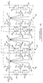
- FIG. 4 shows a typical architecture for an IIR filter comprising three second-order sections cascaded in series between an input x(n) and an output y(n).
- a filter may include an overall gain term G 0 applied to one input of a multiplier 45 which receives input x(n) at its other input.
- the gain term G 0 may be distributed to the individual sections as is known in the art.
- Second order sections 46, 47 and 48 are connected in series to produce a sixth order filter.
- First section 46 includes a multiplier 50 for multiplying the input to section 46 by a coefficient b 0 , 1 .
- the resulting product is provided to one input of a summer 51.
- the output of summer 51 provides the output node for section 46, and is also an internal node of the whole filter.
- the input to section 46 is delayed by one sample period in a unit delay block 52 and then input to a multiplier 53.
- Coefficient b 1,1 is applied to a second input of multiplier 53 and the output is provided to summer 51.
- the output of unit delay block 52 is passed through a further unit delay in unit delay block 54 prior to multiplying it in a multiplier 55 by a coefficient b 2,1 .
- the output of multiplier 55 is provided to yet another input of summer 51.
- the b coefficients provide the feedforward terms for section 46.
- Section 46 also includes feedback terms wherein the output of summer 51 is delayed in a unit delay block 56.
- the delayed output is coupled to a multiplier 57 which also receives a coefficient a 1,1 .
- the output of multiplier 57 is coupled to another input of summer 51.
- the delayed output from unit delay block 56 is passed through a unit delay block 58 and then to an input of a multiplier 59.
- Coefficient a 2,1 is supplied to another input of multiplier 59 and the resulting product is coupled to summer 51.
- the output of summer 51 comprising the internal node for the first section 46, is coupled to the input of second section 47. Sections 46 and 47 are shown overlapping since unit delay blocks 56 and 57 are shared between the two section operations in order to minimise hardware requirements.
- section 47 (from summer 51) is applied to a multiplier 60 which also receives coefficient b 0,2 . Additional b coefficients b 1,2 and b 2,2 are applied to multipliers 62 and 63, respectively, and the resulting products are added in a summer 61.
- Unit delay block 64, multiplier 65, unit delay block 66, and multiplier 67 provide feedback terms using coefficients a 1,2 and a 2,2 , as in the previous section.
- Section 48 operates in the same manner using b coefficients for the third section b 0,3 b 1,3 and b 2,3 and a coefficients a 1,3 and a 2,3 . In order to provide a final filtering of higher order, more second order sections may be cascaded in series after section 48.
- a Butterworth filter structure is used.
- First and second coefficient sets are separately derived for providing a first bandwidth characteristic and a second bandwidth characteristic, respectively, in order to switch a filter between bandwidths while using the same filter hardware and structure as shown in Figure 3.
- a coefficient set refers to all the a and b coefficients for all the filter sections for providing one bandwidth characteristic.
- the present invention gradually changes the overall filter characteristic to eliminate the audible change in frequency response.
- bandwidth were to be slewed in discrete steps by using conventional coefficient design techniques at a number of intermediate bandwidths between the wide and narrow settings, a large amount of memory and/or computational resources would be required. If 50 intermediate steps were used, then 50 different full coefficient sets would have to be stored or calculated, making the slewing function an expensive one to implement. However, applicant has found that by slewing one specially selected filter section in a particular way, the desired result can still be achieved.
- a 1 term is slewed.
- the b 0 , b 1 , and b 2 terms must be adjusted accordingly.
- Slewing a 1 is accomplished by adjusting it slightly (by an adjustment amount) on each iteration of a timing loop, until a 1 is completely changed from its start value to its end value. On each iteration, the b values are determined based on the current value of a 1 . Alternatively, some or all the slewing values could be stored in a table. Note that by changing a 1 without changing a 2 , the corner frequency of the section is changed without changing the Q of the section.
- the start values (when going from narrow to wide) or the end values (when going from wide to narrow) for the slewing of the selected section may correspond to the actual set of coefficients for the selected section when switched to the narrowband characteristic.
- the procedure for slewing from wideband to narrowband begins in step 80 where coefficient a 1 of the selected section is changed by an adjustment amount.
- the total time to slew equals the number of iterations divided by the iteration rate, and the total span of values equals the number of iterations times the adjustment amount.
- a typical slewing time may be about 12 seconds and a typical number of iterations may be about 123. These are not necessarily the same in both slewing directions.
- step 81 the b coefficients of the selected section are calculated and loaded into the filter along with the new value for a 1 .
- the new value for b 0 is determined as k 1 *a 1 +k 2 , where k 1 and k 2 are predetermined constants.
- New values for b 1 and b 2 are determined from b 0 as given above. The a 2 term need not be changed or slewed since it has no effect on the corner frequency of the filter section.
- step 82 a check is made to determine whether the surrogate value of a 1 has been reached. If not, then a loop delay is implemented in step 83 and then a return is made to step 80 for the next iteration. If the surrogate value of a 1 has been reached, then a coefficient swap to the narrow filter coefficient values is made in step 84. If the surrogate values are not equal to the narrow values for the selected section, then the selected section also participates in the swap.
- the procedure for slewing from narrowband to wideband begins in step 90 where all coefficients (except the selected section) are swapped to their wide values. If the surrogate values do not equal the narrow values for the selected section, then the selected section is swapped to the surrogate values in step 91.
- step 92 coefficient a 1 of the selected section is changed by the adjustment amount.
- step 93 the b coefficients of the selected section are calculated and loaded into the selected section along with the new value for a 1 .
- step 94 a check is made to determine whether the end wideband values have been reached. If not, then a loop delay is implemented in step 95 and then a return is made to step 92 for the next iteration. If the wideband values have been reached, then the procedure is done.
- a preferred criteria for selecting the filter section to be slewed will be described with reference to Figures 7A-7D.
- a section with an optimally flat frequency response is one that has a Q value of 0.707, or is critically damped.
- the selected section may well also be the one with a Q value closest to 0.707 in its narrowband configuration, but this is not required since surrogate coefficient values can be used for slewing.
- Figures 7A to 7D show frequency responses for individual sections of the filter.
- Figure 7B corresponds to the flattest frequency response and has a Q value closest to 0.707.
- a section with a lower Q value e.g., Figure 7D
- Figure 7D has a shallower roll-off and is not flat over its passband (considered as a separate filter). If such a section is the one slewed, the whole filter's passband becomes less flat and the corner frequency is not well controlled during slewing.
- a section with a higher Q value is likewise not flat in its passband (e.g., Figure 7A) and is less able to control the corner frequency during slewing.
- a filter section other than the flattest may alternatively be used for slewing.
Landscapes
- Physics & Mathematics (AREA)
- Engineering & Computer Science (AREA)
- Computer Hardware Design (AREA)
- Mathematical Physics (AREA)
- Noise Elimination (AREA)
- Digital Transmission Methods That Use Modulated Carrier Waves (AREA)
- Superheterodyne Receivers (AREA)
- Complex Calculations (AREA)
- Filters That Use Time-Delay Elements (AREA)
Abstract
Description
Claims (10)
- A method of slewing between a first bandwidth characteristic and a second bandwidth characteristic in a switched bandwidth digital filter including a plurality of second-order filter sections (46,47,48), each of said sections comprising respective coefficients having a first set of values in providing said first bandwidth characteristic and having a second set of values in providing said second bandwidth characteristic, said method comprising the steps of:slewing said coefficients of a selected filter section between said first set of values and a surrogate set of values while coefficients in said filter sections other than said selected filter section are held constant;swapping said coefficients of said filter sections other than said selected filter section from their respective first set of values to their respective second set of values.
- A method as claimed in claim 1, wherein said coefficients of said selected filter section are swapped between said surrogate set of values and said second set of values for said selected filter section when said coefficients of said other filter sections are swapped.
- A method as claimed in claim 1, wherein said surrogate set of values is equal to said second set of values of said selected filter section.
- A method as claimed in claim 1, wherein said surrogate set of values provides said selected filter section with a passband characteristic which approximates an overall passband of said digital filter when it is providing its narrower bandwidth characteristic.
- A method as claimed in claim 1, wherein said first bandwidth characteristic is wider than said second bandwidth characteristic, and wherein said slewing step is performed prior to said swapping step.
- A method as claimed in claim 1, wherein said first bandwidth characteristic is narrower than said second bandwidth characteristic, and wherein said swapping step is performed prior to said slewing step.
- A method as claimed in claim 1, wherein said slewing step includes a predetermined number of iterations between said first set of values and said surrogate set of values, and wherein each of said iterations is comprised of changing one of said coefficients within said selected section by a predetermined adjustment value.
- A method as claimed in claim 7, wherein coefficient values used during each of said iterations are retrieved from a memory.
- A method as claimed in claim 7, wherein each of said iterations is comprised of calculating a new value for at least one of said coefficients in response to said changing of a different one of said coefficients by said predetermined adjustment value.
- A method as claimed in claim 1, wherein said selected section is substantially critically damped when said filter is providing its wider bandwidth characteristic.
Applications Claiming Priority (2)
| Application Number | Priority Date | Filing Date | Title |
|---|---|---|---|
| US09/382,727 US6393450B1 (en) | 1999-08-25 | 1999-08-25 | Switched bandwidth digital filters with slewing |
| US382727 | 1999-08-25 |
Publications (3)
| Publication Number | Publication Date |
|---|---|
| EP1079523A2 true EP1079523A2 (en) | 2001-02-28 |
| EP1079523A3 EP1079523A3 (en) | 2004-01-02 |
| EP1079523B1 EP1079523B1 (en) | 2006-03-29 |
Family
ID=23510157
Family Applications (1)
| Application Number | Title | Priority Date | Filing Date |
|---|---|---|---|
| EP00306851A Expired - Lifetime EP1079523B1 (en) | 1999-08-25 | 2000-08-10 | Switched bandwidth digital filters with slewing |
Country Status (4)
| Country | Link |
|---|---|
| US (1) | US6393450B1 (en) |
| EP (1) | EP1079523B1 (en) |
| JP (1) | JP2001119270A (en) |
| DE (1) | DE60026943T2 (en) |
Cited By (1)
| Publication number | Priority date | Publication date | Assignee | Title |
|---|---|---|---|---|
| EP1296455A1 (en) * | 2001-09-25 | 2003-03-26 | Sony International (Europe) GmbH | Memory-efficient realization of a digital filter |
Families Citing this family (6)
| Publication number | Priority date | Publication date | Assignee | Title |
|---|---|---|---|---|
| US6988116B2 (en) * | 2002-04-15 | 2006-01-17 | Visteon Global Technologies, Inc. | Method of designing polynomials for controlling the slewing of adaptive digital films |
| US8417750B2 (en) | 2004-10-13 | 2013-04-09 | Mediatek Inc. | Filters for communication systems |
| US8812571B2 (en) * | 2011-05-12 | 2014-08-19 | Telefonaktiebolaget L M Ericsson (Publ) | Spectrum agile radio |
| US9471673B1 (en) | 2012-03-12 | 2016-10-18 | Google Inc. | Audio matching using time-frequency onsets |
| EP3152919B1 (en) | 2014-06-03 | 2020-02-19 | Dolby Laboratories Licensing Corporation | Passive and active virtual height filter systems for upward firing drivers |
| EP3152920B1 (en) | 2014-06-03 | 2018-11-28 | Dolby Laboratories Licensing Corporation | Audio speakers having upward firing drivers for reflected sound rendering |
Family Cites Families (12)
| Publication number | Priority date | Publication date | Assignee | Title |
|---|---|---|---|---|
| US4356567A (en) | 1977-06-28 | 1982-10-26 | Pioneer Electronic Corporation | Radio receiver with bandwidth switching |
| US4352208A (en) | 1980-03-04 | 1982-09-28 | Motorola, Inc. | Automatic IF selectivity for radio receiver system |
| US4691292A (en) * | 1983-04-13 | 1987-09-01 | Rca Corporation | System for digital multiband filtering |
| DE3333275A1 (en) * | 1983-09-15 | 1985-04-18 | ANT Nachrichtentechnik GmbH, 7150 Backnang | TRANSMISSION ARRANGEMENT FOR DIGITAL SIGNALS |
| DE3702215A1 (en) * | 1987-01-26 | 1988-08-04 | Ant Nachrichtentech | TRANSMISSION ARRANGEMENT FOR DIGITAL SIGNALS |
| DE3724604A1 (en) | 1987-04-15 | 1988-12-01 | H U C Elektronik Gmbh | ARRANGEMENT FOR FILTERING AN FM VHF RECEPTION SIGNAL |
| DE3803446C1 (en) * | 1988-02-05 | 1989-08-10 | Ant Nachrichtentechnik Gmbh, 7150 Backnang, De | |
| DE4005272A1 (en) | 1990-02-20 | 1991-08-22 | Bosch Gmbh Robert | METHOD FOR ZF BANDWIDTH SWITCHING AND ZF BANDWIDTH SWITCHING DEVICE |
| US5287556A (en) | 1990-09-28 | 1994-02-15 | Motorola, Inc. | Interference reduction using an adaptive receiver filter, signal strength, and BER sensing |
| US5307515A (en) | 1991-08-05 | 1994-04-26 | Ford Motor Company | Adjacent channel controller for radio receiver |
| US5777911A (en) * | 1996-02-12 | 1998-07-07 | Analog Devices, Inc. | Digital filtering system |
| GB9607863D0 (en) * | 1996-04-16 | 1996-06-19 | Central Research Lab Ltd | Filter switching method |
-
1999
- 1999-08-25 US US09/382,727 patent/US6393450B1/en not_active Expired - Lifetime
-
2000
- 2000-08-10 DE DE60026943T patent/DE60026943T2/en not_active Expired - Fee Related
- 2000-08-10 EP EP00306851A patent/EP1079523B1/en not_active Expired - Lifetime
- 2000-08-25 JP JP2000255649A patent/JP2001119270A/en active Pending
Cited By (1)
| Publication number | Priority date | Publication date | Assignee | Title |
|---|---|---|---|---|
| EP1296455A1 (en) * | 2001-09-25 | 2003-03-26 | Sony International (Europe) GmbH | Memory-efficient realization of a digital filter |
Also Published As
| Publication number | Publication date |
|---|---|
| DE60026943T2 (en) | 2006-12-21 |
| DE60026943D1 (en) | 2006-05-18 |
| US6393450B1 (en) | 2002-05-21 |
| EP1079523B1 (en) | 2006-03-29 |
| EP1079523A3 (en) | 2004-01-02 |
| JP2001119270A (en) | 2001-04-27 |
Similar Documents
| Publication | Publication Date | Title |
|---|---|---|
| EP1142144B1 (en) | Circuit for a multi-standard communications terminal | |
| US8582780B2 (en) | Configurable recursive digital filter for processing television audio signals | |
| EP1026824B1 (en) | Switched bandwidth digital filters with reduced transients during switching | |
| JP3122793B2 (en) | Method and nonlinear filter for reducing co-channel interference | |
| US6988116B2 (en) | Method of designing polynomials for controlling the slewing of adaptive digital films | |
| JPH09167944A (en) | Equalizer of digitized signal | |
| JPH0629938A (en) | Time-discrete stereo decoder | |
| EP1079523B1 (en) | Switched bandwidth digital filters with slewing | |
| US7035328B2 (en) | Method of slewing a digital filter providing filter sections with matched gain | |
| JPH0766685A (en) | Digital graphic equalizer | |
| US7027502B2 (en) | Run-time coefficient generation for digital filter with slewing bandwidth | |
| US6954774B1 (en) | Bandpass filter with ability to tune a pass frequency, passband gain and filter Q | |
| US7092465B2 (en) | Method and apparatus for processing an amplitude modulated (AM) signal | |
| US5661810A (en) | Circuit arrangement for deriving signals for masking audio signals | |
| EP2651083A1 (en) | Radio receiver with reconfigurable baseband channel filter | |
| JP2003032082A (en) | Digital filter | |
| US20030130751A1 (en) | New filter bank for graphics equalizer implementation | |
| JP2000295120A (en) | Interference wave level detection circuit, narrow band interference wave limiting device using the same and communication equipment using the same | |
| RU59354U1 (en) | WIDTH MULTI-CHANNEL RADIO RECEIVER OF HF RANGE | |
| Bramhapurikar et al. | Design of variable digital FIR filter for software defined radio applications | |
| JP2006129201A (en) | Radio receiver | |
| JPH057129A (en) | Digital signal equalizer | |
| JP2000196497A (en) | Narrow band interference wave limit device and communication equipment using it | |
| JPH09307471A (en) | Am radio receiver | |
| JPH02260811A (en) | Graphic equalizer driving circuit |
Legal Events
| Date | Code | Title | Description |
|---|---|---|---|
| PUAI | Public reference made under article 153(3) epc to a published international application that has entered the european phase |
Free format text: ORIGINAL CODE: 0009012 |
|
| AK | Designated contracting states |
Kind code of ref document: A2 Designated state(s): AT BE CH CY DE DK ES FI FR GB GR IE IT LI LU MC NL PT SE |
|
| AX | Request for extension of the european patent |
Free format text: AL;LT;LV;MK;RO;SI |
|
| PUAL | Search report despatched |
Free format text: ORIGINAL CODE: 0009013 |
|
| AK | Designated contracting states |
Kind code of ref document: A3 Designated state(s): AT BE CH CY DE DK ES FI FR GB GR IE IT LI LU MC NL PT SE |
|
| AX | Request for extension of the european patent |
Extension state: AL LT LV MK RO SI |
|
| 17P | Request for examination filed |
Effective date: 20040702 |
|
| 17Q | First examination report despatched |
Effective date: 20040804 |
|
| AKX | Designation fees paid |
Designated state(s): DE GB NL |
|
| GRAP | Despatch of communication of intention to grant a patent |
Free format text: ORIGINAL CODE: EPIDOSNIGR1 |
|
| GRAS | Grant fee paid |
Free format text: ORIGINAL CODE: EPIDOSNIGR3 |
|
| GRAA | (expected) grant |
Free format text: ORIGINAL CODE: 0009210 |
|
| AK | Designated contracting states |
Kind code of ref document: B1 Designated state(s): DE GB NL |
|
| PG25 | Lapsed in a contracting state [announced via postgrant information from national office to epo] |
Ref country code: NL Free format text: LAPSE BECAUSE OF FAILURE TO SUBMIT A TRANSLATION OF THE DESCRIPTION OR TO PAY THE FEE WITHIN THE PRESCRIBED TIME-LIMIT Effective date: 20060329 |
|
| REG | Reference to a national code |
Ref country code: GB Ref legal event code: FG4D |
|
| REF | Corresponds to: |
Ref document number: 60026943 Country of ref document: DE Date of ref document: 20060518 Kind code of ref document: P |
|
| PGFP | Annual fee paid to national office [announced via postgrant information from national office to epo] |
Ref country code: DE Payment date: 20060824 Year of fee payment: 7 Ref country code: GB Payment date: 20060824 Year of fee payment: 7 |
|
| NLV1 | Nl: lapsed or annulled due to failure to fulfill the requirements of art. 29p and 29m of the patents act | ||
| PLBE | No opposition filed within time limit |
Free format text: ORIGINAL CODE: 0009261 |
|
| STAA | Information on the status of an ep patent application or granted ep patent |
Free format text: STATUS: NO OPPOSITION FILED WITHIN TIME LIMIT |
|
| 26N | No opposition filed |
Effective date: 20070102 |
|
| GBPC | Gb: european patent ceased through non-payment of renewal fee |
Effective date: 20070810 |
|
| PG25 | Lapsed in a contracting state [announced via postgrant information from national office to epo] |
Ref country code: DE Free format text: LAPSE BECAUSE OF NON-PAYMENT OF DUE FEES Effective date: 20080301 |
|
| PG25 | Lapsed in a contracting state [announced via postgrant information from national office to epo] |
Ref country code: GB Free format text: LAPSE BECAUSE OF NON-PAYMENT OF DUE FEES Effective date: 20070810 |