EP1079469A2 - Rear holder-attached connector and method of producing the same - Google Patents
Rear holder-attached connector and method of producing the same Download PDFInfo
- Publication number
- EP1079469A2 EP1079469A2 EP00307160A EP00307160A EP1079469A2 EP 1079469 A2 EP1079469 A2 EP 1079469A2 EP 00307160 A EP00307160 A EP 00307160A EP 00307160 A EP00307160 A EP 00307160A EP 1079469 A2 EP1079469 A2 EP 1079469A2
- Authority
- EP
- European Patent Office
- Prior art keywords
- housing
- rear holder
- retaining
- provisionally
- mold
- Prior art date
- Legal status (The legal status is an assumption and is not a legal conclusion. Google has not performed a legal analysis and makes no representation as to the accuracy of the status listed.)
- Granted
Links
Images





Classifications
-
- H—ELECTRICITY
- H01—ELECTRIC ELEMENTS
- H01R—ELECTRICALLY-CONDUCTIVE CONNECTIONS; STRUCTURAL ASSOCIATIONS OF A PLURALITY OF MUTUALLY-INSULATED ELECTRICAL CONNECTING ELEMENTS; COUPLING DEVICES; CURRENT COLLECTORS
- H01R13/00—Details of coupling devices of the kinds covered by groups H01R12/70 or H01R24/00 - H01R33/00
- H01R13/40—Securing contact members in or to a base or case; Insulating of contact members
- H01R13/42—Securing in a demountable manner
- H01R13/436—Securing a plurality of contact members by one locking piece or operation
- H01R13/4367—Insertion of locking piece from the rear
- H01R13/4368—Insertion of locking piece from the rear comprising a temporary and a final locking position
-
- Y—GENERAL TAGGING OF NEW TECHNOLOGICAL DEVELOPMENTS; GENERAL TAGGING OF CROSS-SECTIONAL TECHNOLOGIES SPANNING OVER SEVERAL SECTIONS OF THE IPC; TECHNICAL SUBJECTS COVERED BY FORMER USPC CROSS-REFERENCE ART COLLECTIONS [XRACs] AND DIGESTS
- Y10—TECHNICAL SUBJECTS COVERED BY FORMER USPC
- Y10S—TECHNICAL SUBJECTS COVERED BY FORMER USPC CROSS-REFERENCE ART COLLECTIONS [XRACs] AND DIGESTS
- Y10S425/00—Plastic article or earthenware shaping or treating: apparatus
- Y10S425/058—Undercut
Definitions
- the present invention relates to a connector with a rear holder and a method of producing the connector, in which a housing and the rear holder are molded in a plurality of metal-molds, and thereafter the rear holder is provisionally retained on the housing by moving the metal-molds, and the rear holder can be completely retained after the insertion of connection terminals.
- a rear holder 70 movable between a provisionally-retained position and a completely-retained position, is provided on a housing 52 in a straddling manner, and is held in the provisionally-retained position, the housing 52 having a plurality of terminal receiving chambers 53.
- Connection terminals 80 are inserted respectively into the terminal receiving chambers 53 from the rear side of the housing 52, and are retained respectively by housing lances 81 provided respectively within the terminal receiving chambers 53. Then, the rear holder 70 is held in the completely-retained position, thereby retaining the connection terminals 80 in a double manner.
- a forwardly downwardly-slanting, retaining hole or slot 72 is formed through each of opposite side walls 71 of the rear holder 70, and secondary retaining projections 73 for respectively retaining the connection terminals 80 in a secondary manner are formed on a lower surface of the rear holder 70 at a front end portion thereof.
- An upper side of each terminal receiving chamber 53 is open as at 53a at a central portion thereof, and the secondary retaining projection 73 is inserted obliquely downwardly into the terminal receiving chamber 53 through this opening 53a when the rear holder is moved from the provisionally-retained position to the completely-retained position.
- provisionally-retaining projections 54 are formed respectively on opposite side surfaces 52a of the housing 52, and also forwardly downwardly-slanting, completely-retaining projections 55 are formed respectively on the opposite side surfaces 52a, and are disposed obliquely forwardly of the provisionally-retaining projections 54, respectively.
- the projections 54, as well as the projections 55, are engageable in the retaining holes 72, respectively.
- connection terminals 80 each connected to a sheathed wire W, are inserted respectively into the terminal receiving chambers 53 from the rear side, and are primarily retained by the housing lances 81, respectively.
- each retaining hole 72 is disengaged from the provisionally-retaining projection 54, and advances obliquely forwardly, and a front end of each side wall 71 slides over the completely-retaining projection 55.
- the retaining holes 72 are retainingly fitted on the completely-retaining projections 55, respectively, and at the same time the secondary retaining projections 73 are inserted respectively into the terminal receiving chambers 53 through the respective openings 53a to secondarily retain the connection terminals 80, respectively.
- the housing 52 and the rear holder 70 are molded separately from each other, and then are brought to an assembling site where the housing and the rear holder are assembled together, the conveyance to the assembling side, the assembling step and an examination step are required, and besides a stock control for each of the housing 52 and the rear holder 70 is necessary.
- a rear holder-attached connector in which a rear holder 70 and a housing 52 are molded by a metal-mold assembly shown in Fig. 14, and also the rear holder 70 is attached to the housing 52 in a provisionally-retained condition, and then the two are removed from the metal-mold assembly.
- the provisionally-retaining metal-mold assembly 90 shown in Fig. 14, comprises a fixed metal-mold 91, a first movable metal-mold 92 capable of moving upward and downward, and a pair of second movable metal-molds 93 and 93 capable of moving right and left.
- the housing 52 is molded by the fixed metal-mold 91, the first movable metal-mold 92 and inner sides of the second movable metal-molds 93 and 93.
- the rear holder 70 is molded by the fixed metal-mold 91, an outer side of the first movable metal-mold 92 and the inner sides of the second movable metal-molds 93 and 93.
- the housing 52 and the rear holder 70 are molded by all of the metal-molds combined together, and then the first movable metal-mold 92 is moved downward, and then the second movable metal-molds 93 and 93 are moved right and left, respectively, that is, away from each other.
- the rear holder 70 and the housing 52 are molded, with the formed provisionally retained on the latter, and when the first movable metal-mold 92 is moved downward, the housing 52 and the rear holder 70 are discharged from the provisionally-retaining metal-mold assembly 90.
- the retaining holes 72 are retainingly engaged with provisionally-retaining projections 54 to hold the rear holder 70 on the housing 52 in the provisionally-retained condition, and also the retaining holes 72 are retainingly engaged with the completely-retaining projections 55 to hold the rear holder 70 on the housing 52 in the completely-retained condition. Therefore, in order that the rear holder will not move or shake relative to the housing in either of the two retained conditions, high dimensional accuracies are required, and this has invited problems that the productivity is lowered and that the cost increases.
- the housing 52 and the rear holder 70 are molded in such a manner that the rear holder 70 is held on the housing 50 in the provisionally-retained condition. Therefore, it is necessary to provide a gap G1 between the inner surface of each side wall 71 of the rear holder 70 and the corresponding side surface of the housing 52, and also it is necessary to provide a gap G2 between the upper surface of the housing 52 and the lower surface of each secondary retaining projection 73 on the rear holder 70, as shown in Fig. 13.
- a thin plate-like partition plate portion 94 for forming the gap G2 is formed on the fixed metal-mold 91, and thin plate-like partition wall portions 95 for respectively forming the gaps G1 are formed on the fixed metal-mold 91, and partition wall portions 96 are formed on the first movable metal-mold 92.
- a thin mold portion need to be provided between the outer periphery of each provisionally-retaining projection 54 and the inner peripheral edge of the corresponding retaining hole 72.
- the metal-molds have such thin plate portions, and this has invited a problem that the durability of the metal-molds is lowered.
- a connector which comprises a housing having a terminal receiving chamber into which a connection terminal is insertable, a rear holder attachable to the housing, the rear holder being operative to be held on the housing in one of a provisionally-retained condition and a completely-retained condition, wherein when the rear holder is provisionally retained on the housing, the connection terminal is insertable in the terminal receiving chamber, and when the rear holder is completely retained on the housing, the connection terminal is retained by the rear holder in the terminal receiving chamber, and a protective rib formed on the housing, the protective rib having portions outwardly projected from opposite side surfaces of the housing, wherein a distance between outer end surfaces of the portions of the protective rib is larger than a width of the rear holder.
- the rear holder includes opposite side walls having retaining holes which are respectively formed in inner surfaces thereof, and retaining pawls respectively formed on the inner surfaces and having forwardly downwardly-slanting surfaces
- the housing has provisionally-retaining projections respectively formed on the opposite side surfaces of the housing at a rear end portion thereof and respectively engaged in the retaining holes of the rear holder when the rear holder is provisionally retained on the housing
- the provisionally-retaining projections each has a plurality of tapering surfaces
- tapering retaining steps are formed on the housing and are disposed respectively adjacent to the provisionally-retaining projections
- the tapering retaining steps are respectively engaged with the retaining pawls
- a forwardly downwardly-slanting abutment surface for guiding the rear holder is formed on an upper surface of the housing at the rear end portion thereof.
- the rear holder is held in the provisionally-retained position and the completely-retained position through the abutting engagement of the retaining pawls with the respective retaining steps and also through the abutting engagement of the inner surface (reverse surface) of the rear holder with the abutment surface.
- the movement of the rear holder for retaining purposes is effected through the relative wide surfaces, and therefore high dimensional accuracy is not required.
- the provisionally-retaining metal-mold assembly comprises a pouring gate communicating with a plurality of gates which branch off from the pouring gate, a fixed metal-mold having at least one central gate among the plurality of gates being disposed in substantially parallel to the terminal receiving chamber, and a plurality of movable metal-molds movable relative to the fixed metal-mold, wherein the central gate of the fixed metal-mold communicates with a mold cavity portion formed by at least one of the movable metal-molds for molding the protective rib.
- the molten resin poured through the central gate, flows through the mold cavity portion of the movable metal-mold for molding the relatively-wide protective rib, and then flows into relatively-narrow mold cavity portions for molding walls forming the terminal receiving chambers in the housing. Accordingly, the molten resin positively flows even into the narrow mold cavity portions, and the yield of the molded housings is enhanced, and the productivity is enhanced, and the cost is reduced.
- a method of producing a connector which includes a housing having a terminal receiving chamber into which a connection terminal is insertable, and a rear holder attachable to the housing, the rear holder being operative to be held on the housing in one of a provisionally-retained condition and a completely-retained condition, wherein when the rear holder is provisionally retained on the housing, the connection terminal is insertable in the terminal receiving chamber, and when the rear holder is completely retained on the housing, the connection terminal is retained by the rear holder in the terminal receiving chamber.
- the method comprises forming a protective rib on the housing to have a distance between outer end surfaces thereof larger than a width of the rear holder, through a provisionally-retaining metal-mold assembly for molding the housing and the rear holder, wherein the provisionally-retaining metal-mold comprises a pouring gate and a plurality of gates branching off from the pouring gate, and includes a fixed metal-mold having at least one central gate among the plurality of gates being disposed in substantially parallel to the terminal receiving chamber, and a plurality of movable metal-molds movable relative to the fixed metal-mold, wherein the central gate of the fixed metal-mold communicates with a mold cavity portion formed by at least one of the movable metal-molds for molding the protective rib.
- the provisionally-retaining metal-mold comprises a pouring gate and a plurality of gates branching off from the pouring gate, and includes a fixed metal-mold having at least one central gate among the plurality of gates being disposed in substantially parallel to the terminal receiving
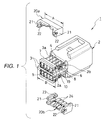
- the rear holder-attached connector 1 of this embodiment comprises the housing 2 of the female type, having a plurality of terminal receiving chambers 3, and the pair of rear holders 20a and 20b each provided on the housing 2 in a straddling manner in a provisionally-retained condition and in a completely-retained condition.
- connection terminals 30 are inserted respectively into the terminal receiving chambers 3 from the rear side, and are retained respectively by housing lances 31 provided respectively within the terminal receiving chambers 3.
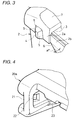
- a retaining hole 22 is formed in an inner surface of each of opposite side walls 21 of the rear holder 20a (20b), and a retaining pawl 23, having a forwardly downwardly-slanting surface, is formed on this inner surface, and provisionally-retaining projections 4 for being engaged respectively in the retaining holes 22 are formed on opposite side surfaces 2a of a rear end portion of the housing 2, tapering surfaces 5 being formed on each provisionally-retaining projection 4 over the entire periphery thereof.
- a tapering retaining step 6 for engagement with the retaining pawl 23 is formed on a side surface 2b of a rear portion of the housing extending from each side surface 2a, the retaining step 6 being slanting forwardly downwardly at an angle a with respect to a horizontal plane.
- a forwardly downwardly-slanting abutment surface 7 of a large width for contact with the inner surface of the rear holder 20a (20b) so as to guide the same is formed on an upper (lower) surface of the rear end portion of the housing 2.
- a guide rail 8 is formed adjacent to each retaining step 6 in parallel relation thereto, and a completely-retaining projection 19 is formed on a side surface of this guide rail 8.
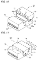
- a relatively-thick protective rib 10 is formed on the housing 2 at the boundary between the upper and lower rows of terminal receiving chambers 3, and projects outwardly from the opposite side surfaces of the housing 2.
- a width B of the protective rib 10 is larger than the width A of the rear holder 20a, 20b, and the protective rib 10 protects the rear holders 20a and 20b so that these rear holders, provisionally retained on the housing 2 within the metal-mold assembly, will not be discharged from the metal-mold assembly to drop, and will not be disengaged from the housing even upon contact with another housing.
- the formation of the protective rib 10 also serves to provide a good flow of a resin poured from the rear side of the housing 2 during the molding operation, and therefore thin partition walls, forming the terminal receiving chambers 3, can be positively molded, thereby enhancing the yield of the molded housings.
- connection terminals 30, each connected to a sheathed wire W are inserted respectively into the terminal receiving chambers 30 from the rear side, and then when the rear holders 20a and 20b are pushed forward, the retaining pawls 23 are guided by the retaining steps 6, respectively.
- the rear holder 20a (20b) advances forwardly downwardly while the inner surface thereof is guided by the abutment surface 7, and the retaining holes 22 are retainingly engaged with the completely-retaining projections 19, respectively.
- the retaining hole 22 is formed in the inner surface of each of the opposite side walls 21 of the rear holder 20a (20b), and the retaining pawl 23, having the forwardly downwardly-slanting surface, is formed on this inner surface.
- the provisionally-retaining projections 4 for being engaged respectively in the retaining holes 22 are formed on the opposite side surfaces 2a of the rear end portion of the housing 2, the tapering surfaces 5 being formed on each provisionally-retaining projection 4 over the entire periphery thereof.
- the tapering retaining step 6 for engagement with the retaining pawl 23 is formed on the side surface 2b of the rear portion of the housing extending from each side surface 2a.
- the forwardly downwardly-slanting abutment surface 7 for contact with the inner surface of the rear holder 20a (20b) so as to guide the same is formed on the upper (lower) surface of the rear end portion of the housing 2.
- the relatively-thick protective rib 10 is formed on the housing 2 at the boundary between the upper and lower rows of terminal receiving chambers 3, and projects outwardly from the opposite side surfaces of the housing 2, and the width B of the protective rib 10 is larger than the width A of the rear holder 20a, 20b.
- the rear holder 20a, 20b is held in the provisionally-retained position and the completely-retained position through the abutting engagement of the retaining pawls 23 with the respective retaining steps 6 and also through the abutting engagement of the inner surface (reverse surface) of the rear holder 20a, 20b with the abutment surface 7.
- the movement of the rear holder for retaining purposes is effected through the relative wide surfaces, and therefore high dimensional accuracy is not required.
- the molten resin can be positively filled in those mold cavity portions for molding the thin partition walls, forming the plurality of terminal receiving chambers 3, so that the yield can be enhanced. Therefore, the productivity is enhanced, and the cost is reduced.
- the provisionally-retaining metal-mold assembly 40 for molding the housing 2 and the rear holders 20a and 20b comprises a fixed metal-mold 41 having gates 49a, 49b and 49c branching off from a pouring gate 48, and a plurality of movable metal-molds 42 to 45 axially movable relative to the fixed metal-mold 41.
- the first movable metal-mold 42 forms the outer side of the housing 2 and the inner sides of the rear holders 20a and 20b, and the second movable metal-mold 43 supporting the first movable metal-mold 42 in a manner to allow an axial movement thereof, third movable metal-molds 44 movably supported on the second movable metal-mold 43 so as to form the outer sides of the rear holders 20a and 20b, and the fourth movable metal-mold 45 for forming a central portion of the housing 2 and for supporting the molded housing 2.
- Compression springs 46 are provided between the first movable metal-mold 42 and the second movable metal-mold 43, and the first movable metal-mold 42 can be moved a distance D away from the second movable metal-mold 43 under the influence of the compression springs 46, as shown in Fig. 8.
- the fixed metal-mold 41 and the movable metal-molds 42 to 45 are combined together as shown in Fig. 7, and in this condition the housing 2 and the rear holders 20a and 20b are molded. At this time, the molten resin is poured into the gates 49a, 49b and 49c branching off from the pouring gate 48 in the fixed metal-mold 41. More specifically, the two rear holders 20a and 20b are molded through the gates 49a and 49b, respectively, while the housing 2 is molded through the central gate 49c.
- the central gate 49c communicates with a mold cavity portion of the movable metal-mold 42 for molding the protective rib 10 (Fig. 1) projecting from the opposite side surfaces of the housing 2 in parallel relation to the terminal receiving chambers 3, and this mold cavity portion communicates with other mold cavity portions for molding the partition walls forming the terminal receiving chambers 3 in the housing 2.
- the molten resin poured through the central gate 49c, flows through the mold cavity portion of the movable metal-mold 42 for molding the relatively-wide protective rib 10, and then flows into the relatively-narrow mold cavity portions for molding the partition walls forming the terminal receiving chambers 3 in the housing 2. Therefore, the molten resin positively flows even into the narrow mold cavity portions, and the yield of the molded housings is enhanced, and the productivity is enhanced, and the cost is reduced.
- the movable metal-molds 42 to 45 is moved a distance C away from the fixed metal-mold 41, and at the same time the fourth movable metal-mold 45 is moved back to a position where this metal-mold 45 holds the rear end portion of the molded housing 2, that is, the first movable metal-mold 42 is moved back a distance D under the influence of the compression springs 46, as shown in Fig. 8.
- spaces 47 are formed inwardly of the third movable metal-molds 44, respectively, and the third movable metal-molds 44 are moved inwardly.
- the provisionally-retaining metal-mold assembly 40 comprises the fixed metal-mold 41, having the gates 49a, 49b and 49c branching off from the pouring gate 48, and the plurality of movable metal-molds 42 to 45 movable in the axial direction relative to the fixed metal-mold 41.
- the central gate 49c communicates with the mold cavity portion of the movable metal-mold 42 for molding the protective rib 10 projecting from the opposite side surfaces of the housing 2.
- This mold cavity portion communicates with the mold cavity portions for molding the partition walls forming the terminal receiving chambers 3 in the housing 2.
- the molten resin poured through the central gate 49c, flows through the mold cavity portion of the movable metal-mold 42 for molding the relatively-wide protective rib 10, and then flows into the relatively-narrow mold cavity portions for molding the partition walls forming the terminal receiving chambers 3 in the housing 2. Therefore, the molten resin positively flows even into the narrow mold cavity portions, and the yield of the molded housings is enhanced.
- the rear holder-attached connector of the present invention is not limited to the above embodiment, but suitable modifications can be made.
- these third movable metal-molds 44 need only to be driven in a direction perpendicular to the axis of the housing, and a system for driving these third movable metal-molds 44 in a horizontal direction can be used.
- the present invention can be applied to a rear holder-attached connector of the male type.
- the rear holder has the retaining hole, formed in the inner surface of each of the opposite side walls thereof, and also has the retaining pawl formed on this inner surface, the retaining pawl having the forwardly downwardly-slanting surface, and the provisionally-retaining projections for being engaged respectively in the retaining holes are formed respectively on the opposite side surfaces of the rear end portion of the housing, the tapering surfaces being formed on each of the provisionally-retaining projections over the entire periphery thereof, and the tapering retaining steps for being engaged respectively with the retaining pawls are formed on the housing, and are disposed in the vicinity of the provisionally-retaining projections, respectively, and the forwardly downwardly-slanting abutment surface for guiding the rear holder is formed on the upper surface of the housing at the rear end portion thereof, and the protective rib is formed on the housing, and projects outwardly from the opposite side surfaces of the housing, the width of the protective rib being larger than the width of the
- the rear holder is held in the provisionally-retained position and the completely-retained position through the abutting engagement of the retaining pawls with the respective retaining steps and also through the abutting engagement of the inner surface (reverse surface) of the rear holder with the abutment surface.
- the movement of the rear holder for retaining purposes is effected through the relative wide surfaces, and therefore high dimensional accuracy is not required. Therefore, the productivity is enhanced, and the production cost is reduced.
- the rear holders since there is provided the protective rib which is larger in width than the rear holder, the rear holders, provisionally retained on the housing within the metal-mold assembly, will not be discharged from the metal-mold assembly to drop, and will not be disengaged from the housing even upon contact with another housing.
- the rear holder-attached connector of high reliability.
- the provisionally-retaining metal-mold assembly for molding the housing and the rear holders comprises the fixed metal-mold, having the plurality of gates branching off from the pouring gate, and the plurality of movable metal-molds movable relative to the fixed metal-mold, at least the central one among the plurality of gates being disposed substantially parallel to the terminal receiving chambers.
- the central gate communicates with the mold cavity portion of the movable metal-mold for molding the protective rib which is formed on the housing, and projects outwardly from the opposite side surfaces of the housing, the width of the protective rib being larger than the width of the rear holder.
- the molten resin poured through the central gate, flows through the mold cavity portion of the movable metal-mold for molding the relatively-wide protective rib, and then flows into relatively-narrow mold cavity portions for molding the partition walls forming the terminal receiving chambers in the housing, and therefore, the molten resin positively flows even into the narrow mold cavity portions. Therefore, the yield of the molded housings is enhanced, and the productivity is enhanced, and the production cost is reduced.
Landscapes
- Connector Housings Or Holding Contact Members (AREA)
- Manufacturing Of Electrical Connectors (AREA)
Abstract
Description
Claims (4)
- A connector, comprising:wherein a distance between outer end surfaces of the portions of the protective rib is larger than a width of the rear holder.a housing having a terminal receiving chamber into which a connection terminal is insertable;a rear holder attachable to the housing, the rear holder being operative to be held on the housing in one of a provisionally-retained condition and a completely-retained condition, wherein when the rear holder is provisionally retained on the housing, the connection terminal is insertable in the terminal receiving chamber, and when the rear holder is completely retained on the housing, the connection terminal is retained by the rear holder in the terminal receiving chamber; anda protective rib formed on the housing, the protective rib having portions outwardly projected from opposite side surfaces of the housing,
- The connector of claim 1, wherein the rear holder includes opposite side walls having retaining holes which are respectively formed in inner surfaces thereof, and retaining pawls respectively formed on the inner surfaces and having forwardly downwardly-slanting surfaces, and
wherein the housing has provisionally-retaining projections respectively formed on the opposite side surfaces of the housing at a rear end portion thereof and respectively engaged in the retaining holes of the rear holder when the rear holder is provisionally retained on the housing, the provisionally-retaining projections each has a plurality of tapering surfaces, tapering retaining steps are formed on the housing and are disposed respectively adjacent to the provisionally-retaining projections, the tapering retaining steps are respectively engaged with the retaining pawls, and a forwardly downwardly-slanting abutment surface for guiding the rear holder is formed on an upper surface of the housing at the rear end portion thereof. - A provisionally-retaining metal-mold assembly for molding the connector recited in claim 1, comprising:wherein the central gate of the fixed metal-mold communicates with a mold cavity portion formed by at least one of the movable metal-molds for molding the protective rib.a pouring gate communicating with a plurality of gates which branch off from the pouring gate;a fixed metal-mold having at least one central gate among the plurality of gates being disposed in substantially parallel to the terminal receiving chamber; anda plurality of movable metal-molds movable relative to the fixed metal-mold,
- A method of producing a connector which includes a housing having a terminal receiving chamber into which a connection terminal is insertable, and a rear holder attachable to the housing, the rear holder being operative to be held on the housing in one of a provisionally-retained condition and a completely-retained condition, wherein when the rear holder is provisionally retained on the housing, the connection terminal is insertable in the terminal receiving chamber, and when the rear holder is completely retained on the housing, the connection terminal is retained by the rear holder in the terminal receiving chamber, the method comprising:
forming a protective rib on the housing to have a distance between outer end surfaces thereof larger than a width of the rear holder, through a provisionally-retaining metal-mold assembly for molding the housing and the rear holder,
wherein the provisionally-retaining metal-mold comprises a pouring gate and a plurality of gates branching off from the pouring gate, and includes a fixed metal-mold having at least one central gate among the plurality of gates being disposed in substantially parallel to the terminal receiving chamber, and a plurality of movable metal-molds movable relative to the fixed metal-mold, wherein the central gate of the fixed metal-mold communicates with a mold cavity portion formed by at least one of the movable metal-molds for molding the protective rib.
Applications Claiming Priority (2)
| Application Number | Priority Date | Filing Date | Title |
|---|---|---|---|
| JP23726299A JP3690785B2 (en) | 1999-08-24 | 1999-08-24 | Connector with rear holder and manufacturing method thereof |
| JP23726299 | 1999-08-24 |
Publications (3)
| Publication Number | Publication Date |
|---|---|
| EP1079469A2 true EP1079469A2 (en) | 2001-02-28 |
| EP1079469A3 EP1079469A3 (en) | 2002-03-13 |
| EP1079469B1 EP1079469B1 (en) | 2003-11-26 |
Family
ID=17012809
Family Applications (1)
| Application Number | Title | Priority Date | Filing Date |
|---|---|---|---|
| EP00307160A Expired - Lifetime EP1079469B1 (en) | 1999-08-24 | 2000-08-21 | Rear holder-attached connector and method of producing the same |
Country Status (4)
| Country | Link |
|---|---|
| US (3) | US6575795B1 (en) |
| EP (1) | EP1079469B1 (en) |
| JP (1) | JP3690785B2 (en) |
| DE (1) | DE60006750T2 (en) |
Cited By (1)
| Publication number | Priority date | Publication date | Assignee | Title |
|---|---|---|---|---|
| US6536108B2 (en) * | 1999-12-20 | 2003-03-25 | Yazaki Corporation | Method of and apparatus for producing rear holder-attached connector |
Families Citing this family (10)
| Publication number | Priority date | Publication date | Assignee | Title |
|---|---|---|---|---|
| JP5258667B2 (en) * | 2009-04-23 | 2013-08-07 | 矢崎総業株式会社 | Housing mold structure, housing molding method, and housing |
| TW201136077A (en) * | 2010-04-01 | 2011-10-16 | Hon Hai Prec Ind Co Ltd | Device and method for manufacturing optical couple connetor |
| US8147279B1 (en) * | 2011-03-28 | 2012-04-03 | Tyco Electronics Corporation | Electrical connector having overstress protection |
| JP5707252B2 (en) * | 2011-06-24 | 2015-04-22 | 矢崎総業株式会社 | connector |
| US8721374B2 (en) * | 2011-07-22 | 2014-05-13 | Lear Corporation | Electrical connector |
| US8951066B2 (en) | 2011-07-22 | 2015-02-10 | Lear Corporation | Electrical connector |
| US9484660B2 (en) * | 2014-11-13 | 2016-11-01 | Tyco Electronics Corporation | Electrical connector |
| KR20190117541A (en) | 2017-01-20 | 2019-10-16 | 이뮨 시스템 레귤레이션 홀딩 에이비 | Novel Compounds (Imunorelin) |
| JP7560966B2 (en) * | 2020-06-08 | 2024-10-03 | モレックス エルエルシー | Cable terminals and connectors |
| JP7484769B2 (en) * | 2021-02-24 | 2024-05-16 | 株式会社オートネットワーク技術研究所 | connector |
Family Cites Families (14)
| Publication number | Priority date | Publication date | Assignee | Title |
|---|---|---|---|---|
| US4403933A (en) * | 1982-04-14 | 1983-09-13 | Fischer & Porter Company | Apparatus for injection-molding a liner onto a metal spool |
| US4787860A (en) * | 1987-08-28 | 1988-11-29 | E. I. Du Pont De Nemours And Company | Connector system having combined latch and polarization member |
| JP2581477Y2 (en) * | 1993-05-07 | 1998-09-21 | 住友電装株式会社 | connector |
| JP2910558B2 (en) * | 1994-04-08 | 1999-06-23 | 住友電装株式会社 | connector |
| US5814356A (en) * | 1995-03-10 | 1998-09-29 | Sumitomo Wiring Systems, Ltd. | Manufacturing metal mold for assembling a resin molded assembly |
| DE69609101T2 (en) | 1995-03-16 | 2001-02-15 | Sumitomo Wiring Systems, Ltd. | Connector assembly with a locking device, a method of manufacturing the same and a mold therefor |
| JP3275994B2 (en) | 1995-03-16 | 2002-04-22 | 住友電装株式会社 | Connector with retainer, method of manufacturing the same, and molding die |
| JP4140667B2 (en) * | 1996-08-01 | 2008-08-27 | 住友電装株式会社 | connector |
| JP3301329B2 (en) * | 1996-12-27 | 2002-07-15 | 住友電装株式会社 | connector |
| DE69938685D1 (en) * | 1998-03-27 | 2008-06-26 | Sumitomo Wiring Systems | Electrical connector with a housing and a holder |
| US6106340A (en) * | 1998-04-30 | 2000-08-22 | The Whitaker Corporation | Electrical connector with deflectable secondary |
| JP2001118626A (en) * | 1999-10-18 | 2001-04-27 | Yazaki Corp | Connector housing and its manufacturing method |
| JP3625167B2 (en) * | 1999-12-20 | 2005-03-02 | 矢崎総業株式会社 | Molding temporary locking mold and molding temporary locking method |
| JP3690788B2 (en) * | 1999-12-27 | 2005-08-31 | 矢崎総業株式会社 | Connector with rear holder and manufacturing method thereof |
-
1999
- 1999-08-24 JP JP23726299A patent/JP3690785B2/en not_active Expired - Fee Related
-
2000
- 2000-08-21 EP EP00307160A patent/EP1079469B1/en not_active Expired - Lifetime
- 2000-08-21 DE DE60006750T patent/DE60006750T2/en not_active Expired - Lifetime
- 2000-08-22 US US09/642,669 patent/US6575795B1/en not_active Expired - Lifetime
-
2002
- 2002-05-06 US US10/138,658 patent/US6705854B2/en not_active Expired - Lifetime
-
2003
- 2003-12-30 US US10/747,045 patent/US6869555B2/en not_active Expired - Lifetime
Cited By (1)
| Publication number | Priority date | Publication date | Assignee | Title |
|---|---|---|---|---|
| US6536108B2 (en) * | 1999-12-20 | 2003-03-25 | Yazaki Corporation | Method of and apparatus for producing rear holder-attached connector |
Also Published As
| Publication number | Publication date |
|---|---|
| EP1079469B1 (en) | 2003-11-26 |
| DE60006750D1 (en) | 2004-01-08 |
| US6869555B2 (en) | 2005-03-22 |
| US20020127921A1 (en) | 2002-09-12 |
| DE60006750T2 (en) | 2004-09-23 |
| US6575795B1 (en) | 2003-06-10 |
| US6705854B2 (en) | 2004-03-16 |
| US20040152369A1 (en) | 2004-08-05 |
| JP2001068198A (en) | 2001-03-16 |
| EP1079469A3 (en) | 2002-03-13 |
| JP3690785B2 (en) | 2005-08-31 |
Similar Documents
| Publication | Publication Date | Title |
|---|---|---|
| EP1079469B1 (en) | Rear holder-attached connector and method of producing the same | |
| EP0740366B1 (en) | A connector, a method for manufacturing the same, a device for molding the same,and a method for mounting a retainer | |
| US6699420B2 (en) | Method of manufacturing a connector having rear holders | |
| JP2002329554A (en) | Connector | |
| EP1054483A2 (en) | Joint connector and method of producing joint connector | |
| EP0732772A2 (en) | Connector assembly with a retainer, a method for producing the same, and a molding die for producing the same | |
| US6547594B2 (en) | Connector | |
| US5709831A (en) | Method of producing connector with rear holder | |
| US6851987B2 (en) | Connector | |
| US20010055907A1 (en) | Connector | |
| EP1100156A1 (en) | A connector and a connector assembly | |
| US6609932B2 (en) | Watertight connector and a method for mounting it | |
| EP1416593B1 (en) | A connector | |
| US7001215B2 (en) | Connector with inner and outer housings | |
| US6632392B2 (en) | Method of manufacturing a connector housing | |
| US7131869B2 (en) | Connector and resin molding method therefor | |
| EP0884805A2 (en) | Connector and method for manufacturing the same | |
| US11757227B2 (en) | Connector having rear holder | |
| EP1164663B1 (en) | Structure for engaging connector housing and rear holder | |
| US6280234B1 (en) | Wire shaking prevention structure of connector | |
| US7104783B2 (en) | Mold tooling having cavity stabilizers | |
| JP3826800B2 (en) | connector | |
| JP2005005126A (en) | connector | |
| JP3225783B2 (en) | Method of manufacturing connector | |
| JP2001060473A (en) | Connector housing |
Legal Events
| Date | Code | Title | Description |
|---|---|---|---|
| PUAI | Public reference made under article 153(3) epc to a published international application that has entered the european phase |
Free format text: ORIGINAL CODE: 0009012 |
|
| AK | Designated contracting states |
Kind code of ref document: A2 Designated state(s): DE FR GB Kind code of ref document: A2 Designated state(s): AT BE CH CY DE DK ES FI FR GB GR IE IT LI LU MC NL PT SE |
|
| AX | Request for extension of the european patent |
Free format text: AL;LT;LV;MK;RO;SI |
|
| PUAL | Search report despatched |
Free format text: ORIGINAL CODE: 0009013 |
|
| AK | Designated contracting states |
Kind code of ref document: A3 Designated state(s): AT BE CH CY DE DK ES FI FR GB GR IE IT LI LU MC NL PT SE |
|
| AX | Request for extension of the european patent |
Free format text: AL;LT;LV;MK;RO;SI |
|
| 17P | Request for examination filed |
Effective date: 20020826 |
|
| AKX | Designation fees paid |
Free format text: DE FR GB |
|
| 17Q | First examination report despatched |
Effective date: 20030214 |
|
| GRAH | Despatch of communication of intention to grant a patent |
Free format text: ORIGINAL CODE: EPIDOS IGRA |
|
| GRAS | Grant fee paid |
Free format text: ORIGINAL CODE: EPIDOSNIGR3 |
|
| GRAA | (expected) grant |
Free format text: ORIGINAL CODE: 0009210 |
|
| AK | Designated contracting states |
Kind code of ref document: B1 Designated state(s): DE FR GB |
|
| REG | Reference to a national code |
Ref country code: GB Ref legal event code: FG4D |
|
| REF | Corresponds to: |
Ref document number: 60006750 Country of ref document: DE Date of ref document: 20040108 Kind code of ref document: P |
|
| REG | Reference to a national code |
Ref country code: IE Ref legal event code: FG4D |
|
| ET | Fr: translation filed | ||
| PLBE | No opposition filed within time limit |
Free format text: ORIGINAL CODE: 0009261 |
|
| STAA | Information on the status of an ep patent application or granted ep patent |
Free format text: STATUS: NO OPPOSITION FILED WITHIN TIME LIMIT |
|
| 26N | No opposition filed |
Effective date: 20040827 |
|
| REG | Reference to a national code |
Ref country code: IE Ref legal event code: MM4A |
|
| REG | Reference to a national code |
Ref country code: FR Ref legal event code: PLFP Year of fee payment: 17 |
|
| REG | Reference to a national code |
Ref country code: FR Ref legal event code: PLFP Year of fee payment: 18 |
|
| REG | Reference to a national code |
Ref country code: FR Ref legal event code: PLFP Year of fee payment: 19 |
|
| PGFP | Annual fee paid to national office [announced via postgrant information from national office to epo] |
Ref country code: DE Payment date: 20190806 Year of fee payment: 20 Ref country code: FR Payment date: 20190815 Year of fee payment: 20 |
|
| PGFP | Annual fee paid to national office [announced via postgrant information from national office to epo] |
Ref country code: GB Payment date: 20190822 Year of fee payment: 20 |
|
| REG | Reference to a national code |
Ref country code: DE Ref legal event code: R071 Ref document number: 60006750 Country of ref document: DE |
|
| REG | Reference to a national code |
Ref country code: GB Ref legal event code: PE20 Expiry date: 20200820 |
|
| PG25 | Lapsed in a contracting state [announced via postgrant information from national office to epo] |
Ref country code: GB Free format text: LAPSE BECAUSE OF EXPIRATION OF PROTECTION Effective date: 20200820 |