EP1079468A1 - Connector having improved high-voltage surge performance - Google Patents
Connector having improved high-voltage surge performance Download PDFInfo
- Publication number
- EP1079468A1 EP1079468A1 EP00306936A EP00306936A EP1079468A1 EP 1079468 A1 EP1079468 A1 EP 1079468A1 EP 00306936 A EP00306936 A EP 00306936A EP 00306936 A EP00306936 A EP 00306936A EP 1079468 A1 EP1079468 A1 EP 1079468A1
- Authority
- EP
- European Patent Office
- Prior art keywords
- molding
- connector
- base
- pins
- improvement
- Prior art date
- Legal status (The legal status is an assumption and is not a legal conclusion. Google has not performed a legal analysis and makes no representation as to the accuracy of the status listed.)
- Granted
Links
- 238000000465 moulding Methods 0.000 claims abstract description 29
- 230000008719 thickening Effects 0.000 abstract 1
- 239000004020 conductor Substances 0.000 description 5
- 238000012986 modification Methods 0.000 description 3
- 230000004048 modification Effects 0.000 description 3
- 230000003467 diminishing effect Effects 0.000 description 1
- 239000012212 insulator Substances 0.000 description 1
- 239000002184 metal Substances 0.000 description 1
- 238000000926 separation method Methods 0.000 description 1
Images
Classifications
-
- H—ELECTRICITY
- H01—ELECTRIC ELEMENTS
- H01R—ELECTRICALLY-CONDUCTIVE CONNECTIONS; STRUCTURAL ASSOCIATIONS OF A PLURALITY OF MUTUALLY-INSULATED ELECTRICAL CONNECTING ELEMENTS; COUPLING DEVICES; CURRENT COLLECTORS
- H01R13/00—Details of coupling devices of the kinds covered by groups H01R12/70 or H01R24/00 - H01R33/00
- H01R13/46—Bases; Cases
- H01R13/53—Bases or cases for heavy duty; Bases or cases for high voltage with means for preventing corona or arcing
-
- H—ELECTRICITY
- H01—ELECTRIC ELEMENTS
- H01R—ELECTRICALLY-CONDUCTIVE CONNECTIONS; STRUCTURAL ASSOCIATIONS OF A PLURALITY OF MUTUALLY-INSULATED ELECTRICAL CONNECTING ELEMENTS; COUPLING DEVICES; CURRENT COLLECTORS
- H01R13/00—Details of coupling devices of the kinds covered by groups H01R12/70 or H01R24/00 - H01R33/00
- H01R13/02—Contact members
- H01R13/04—Pins or blades for co-operation with sockets
-
- H—ELECTRICITY
- H01—ELECTRIC ELEMENTS
- H01R—ELECTRICALLY-CONDUCTIVE CONNECTIONS; STRUCTURAL ASSOCIATIONS OF A PLURALITY OF MUTUALLY-INSULATED ELECTRICAL CONNECTING ELEMENTS; COUPLING DEVICES; CURRENT COLLECTORS
- H01R13/00—Details of coupling devices of the kinds covered by groups H01R12/70 or H01R24/00 - H01R33/00
- H01R13/40—Securing contact members in or to a base or case; Insulating of contact members
- H01R13/405—Securing in non-demountable manner, e.g. moulding, riveting
Definitions
- This invention relates to the configuration of electrical connectors.
- a representative of such a connector is the communications industry-standard Centronic connector, which mounts on printed circuit leads of a circuit board and connects the circuit board to off-board multi-lead cables.
- a standard connector is modified in such a way that it meets more stringent high-voltage surge tests, yet still complies with the industry-standard specification for that connector. This is achieved through increasing the free-air distance between adjacent conductors ("pins") of the connector by modifying their shape but without changing their size, position, or separation.
- each pin in a connector that has an insulating molding and a plurality of conductive pins extending from the molding, each pin has a base that extends partly out of the molding with a leg of the pin narrower than the base in that portion extending from the base.
- the base tapers to the leg along an entire length thereof between the leg and the molding.
- the taper may be monotonic or concave.
- the tapered portion of the base extends into the molding.
- the molding defines ribs that extend outwardly therefrom between adjacent pins.
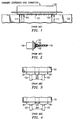
- FIG. 1 shows a side view and FIG. 2 shows an end view of a standard Centronic connector 100.
- Connector 100 includes an insulating (plastic) molding 101 through which extend two rows of a plurality of pins 102.
- Connector 100 mounts on an edge of a printed circuit (PC) board 110.
- the two rows of pins 102 straddle the edge of PC board 110 and connect to printed leads 111 of PC board 110 with one row of pins 102 on each face of PC board 110.
- FIGS. 3 and 4 show a top view of two adjacent pins 102 in more detail.
- Each pin 102 is made from a sheet of metal. It includes a wider base 301 which extends through and out of molding 101, and a narrower leg 300 which extends from base 301 and connects pin 102 to a PC lead 111 by being soldered thereto. Pins 102 are evenly spaced from each other, and the shortest distance between them is distance 120 between their bases 301.
- Bases 301 typically are rectangular as shown in FIG. 3, or rectangular-chamfered as shown in FIG. 4.
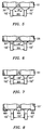
- FIG. 5 shows a pair of adjacent pins 102' that have the portion of base 301' which extends from molding 101 shaped substantially as a triangle, monotonically tapering toward leg 300. Therefore, at all points along pin 102 the new free-air distance 120' between pins 102' is greater than or equal to distance 120.
- the tapered portion of base 301' extends into molding 101, as shown in FIG. 6. This may be accomplished either by making the tapered portion longer, or by making molding 101 thicker.
- FIG. 7 shows an alternative embodiment, with a pair of adjacent pins 102'' that have the portion of base 301'' which extends from molding 101 concavely curved and tapering toward leg 300. Therefore, at all points along pin 102'', the new free-air distance 120'' between pins 102'' is greater than or equal to distance 120. Moreover, at substantially all points along the tapered portion of bases 301'', free-air distance 120'' is greater than free-air distance 120' of the embodiment of FIG. 5. Tapered portions of bases 301'' may likewise extend into molding 101 in the manner of FIG. 6.
- free-air distance 120'' may be further increased by using a molding 101' that has ribs 800 which extend outwardly between adjacent pins 102'', as shown in FIG. 8 or the molding can be made thicker.
- a molding 101' may also be used to advantage with the embodiment of FIGS. 3-6.
Landscapes
- Connector Housings Or Holding Contact Members (AREA)
- Details Of Connecting Devices For Male And Female Coupling (AREA)
- Coupling Device And Connection With Printed Circuit (AREA)
Abstract
Description
- This invention relates to the configuration of electrical connectors.
- Myriads of designs exist for electrical connectors. Most include a plurality of closely-spaced contacts for connecting to individual conductors of electrical signals. Many of these connector designs have become de jure or de facto standards for different applications. A representative of such a connector is the communications industry-standard Centronic connector, which mounts on printed circuit leads of a circuit board and connects the circuit board to off-board multi-lead cables.
- Equipment in which such connectors are typically used must often pass rigorous electrical tests before it can be sold. For example, telecommunications equipment in which the Centronic connector is used to connect to external communications tines must in many countries pass a high-voltage surge test wherein the conductors of the connector must withstand a 1 KV surge signal without arcing (shorting) to adjacent conductors. The connector is designed to pass such foreseen tests.
- Unfortunately, some jurisdictions have seen fit to impose more stringent tests over time. For example, some jurisdictions now require the above-mentioned telecommunications equipment to pass a 1.5 KV high-voltage surge test. Such tests were not foreseen and therefore not taken into consideration in the design of the connector, with the consequence that the connector does not pass this test. Of course, one can redesign the connector to pass the test, e.g., by increasing the spacing of the connector's conductors, or one can substitute a different kind of connector that is robust enough to pass the test. But the use of such different, non-standard, connectors would destroy the equipment's compliance with the industry standards and would also require the use of non-standard external telecommunications connectors that would subsequently attach to these non-standard connectors.
- This invention is directed to meeting these needs and solving these problems of the prior art. Generally according to the invention, a standard connector is modified in such a way that it meets more stringent high-voltage surge tests, yet still complies with the industry-standard specification for that connector. This is achieved through increasing the free-air distance between adjacent conductors ("pins") of the connector by modifying their shape but without changing their size, position, or separation.
- Specifically, according to the invention, in a connector that has an insulating molding and a plurality of conductive pins extending from the molding, each pin has a base that extends partly out of the molding with a leg of the pin narrower than the base in that portion extending from the base. The base tapers to the leg along an entire length thereof between the leg and the molding. The taper may be monotonic or concave. Preferably, the tapered portion of the base extends into the molding. Also preferably, the molding defines ribs that extend outwardly therefrom between adjacent pins.
- These and other features and advantages of the invention will become evident from the following description of an illustrative embodiment of the invention considered together with the drawing.
-
- FIG. 1 is a side view of a conventional Centronic connector;
- FIG. 2 is an end view of the connector of FIG. 1;
- FIGS. 3 and 4 are top views of two conventional embodiments of adjacent pins of the connector of FIG. 1;
- FIG. 5 is a top view of a first embodiment of adjacent pins of the connector of FIG. 1 modified according to the invention;
- FIG. 6 is a top view of a second embodiment of adjacent pins of the connector of FIG. 1 modified according to the invention;
- FIG. 7 is a top view of a third embodiment of adjacent pins of the connector of FIG. 1 modified according to the invention; and
- FIG. 8 is a top view of a fourth embodiment of adjacent pins of the connector of FIG. 1 modified according to the invention.
-
- FIG. 1 shows a side view and FIG. 2 shows an end view of a standard
Centronic connector 100.Connector 100 includes an insulating (plastic)molding 101 through which extend two rows of a plurality ofpins 102.Connector 100 mounts on an edge of a printed circuit (PC)board 110. The two rows ofpins 102 straddle the edge ofPC board 110 and connect to printedleads 111 ofPC board 110 with one row ofpins 102 on each face ofPC board 110. - FIGS. 3 and 4 show a top view of two
adjacent pins 102 in more detail. Eachpin 102 is made from a sheet of metal. It includes awider base 301 which extends through and out ofmolding 101, and anarrower leg 300 which extends frombase 301 and connectspin 102 to aPC lead 111 by being soldered thereto.Pins 102 are evenly spaced from each other, and the shortest distance between them isdistance 120 between theirbases 301.Bases 301 typically are rectangular as shown in FIG. 3, or rectangular-chamfered as shown in FIG. 4. - During a high-voltage surge test, it is free-
air distance 120 betweenadjacent pins 102 that determines whatvoltage pins 102 can withstand without arcing. (The distance betweenpins 102 withinmolding 101 is not critical, becausemolding 101 is a better insulator than air.) Therefore, to increase the voltage thatpins 102 can withstand without arcing, it is desirable to increase free-air distance 120 betweenadjacent pins 102. But this must be done without changing the size or the spacing ofpins 102, which are dictated by the standard forconnector 100 as well as by pin mechanical-strength considerations. - According to the invention, free-
air distance 120 betweenadjacent pins 102 is increased without changing the size or the spacing ofpins 102. Various ways of accomplishing this are shown in FIGS. 5-8. FIG. 5 shows a pair of adjacent pins 102' that have the portion ofbase 301' which extends frommolding 101 shaped substantially as a triangle, monotonically tapering towardleg 300. Therefore, at all points alongpin 102 the new free-air distance 120' between pins 102' is greater than or equal todistance 120. To ensure that distance 120' is always greater thatdistance 120 alongbases 301', the tapered portion ofbase 301' extends intomolding 101, as shown in FIG. 6. This may be accomplished either by making the tapered portion longer, or by makingmolding 101 thicker. - FIG. 7 shows an alternative embodiment, with a pair of adjacent pins 102'' that have the portion of
base 301'' which extends from molding 101 concavely curved and tapering towardleg 300. Therefore, at all points along pin 102'', the new free-air distance 120'' between pins 102'' is greater than or equal todistance 120. Moreover, at substantially all points along the tapered portion ofbases 301'', free-air distance 120'' is greater than free-air distance 120' of the embodiment of FIG. 5. Tapered portions ofbases 301'' may likewise extend intomolding 101 in the manner of FIG. 6. Moreover, free-air distance 120'' may be further increased by using a molding 101' that hasribs 800 which extend outwardly between adjacent pins 102'', as shown in FIG. 8 or the molding can be made thicker. Such a molding 101' may also be used to advantage with the embodiment of FIGS. 3-6. - Of course, various changes and modifications to the illustrative embodiments described above will be apparent to those skilled in the art. Such changes and modifications can be made without departing from the spirit and the scope of the invention and without diminishing its attendant advantages. It is therefore intended that such changes and modifications be covered by the following claims except insofar as limited by the prior art.
Claims (6)
- In a connector having an insulating molding and a plurality of conductive pins extending from the molding, each pin having a base extending partly out of the molding and a leg narrower than the base extending from the base, the improvement comprising:the base tapering to the leg along an entire length thereof between the leg and the molding.
- The improvement of claim 1 wherein:the base tapers monotonically.
- The improvement of claim 1 wherein:the base tapers concavely.
- The improvement of claim 1 wherein:the tapered length of the base extends into the molding.
- The improvement of claim 1 further comprising:the molding defining ribs extending outwardly therefrom between adjacent pins.
- The improvement of claim 1 further comprising:the molding being thicker and extending outwardly over the pins.
Applications Claiming Priority (2)
| Application Number | Priority Date | Filing Date | Title |
|---|---|---|---|
| US379498 | 1999-08-23 | ||
| US09/379,498 US6247940B1 (en) | 1999-08-23 | 1999-08-23 | Connector having improved high-voltage surge performance |
Publications (2)
| Publication Number | Publication Date |
|---|---|
| EP1079468A1 true EP1079468A1 (en) | 2001-02-28 |
| EP1079468B1 EP1079468B1 (en) | 2002-10-23 |
Family
ID=23497510
Family Applications (1)
| Application Number | Title | Priority Date | Filing Date |
|---|---|---|---|
| EP00306936A Expired - Lifetime EP1079468B1 (en) | 1999-08-23 | 2000-08-14 | Connector having improved high-voltage surge performance |
Country Status (6)
| Country | Link |
|---|---|
| US (1) | US6247940B1 (en) |
| EP (1) | EP1079468B1 (en) |
| JP (1) | JP2001076810A (en) |
| AU (1) | AU5339700A (en) |
| CA (1) | CA2315470A1 (en) |
| DE (1) | DE60000643T2 (en) |
Families Citing this family (2)
| Publication number | Priority date | Publication date | Assignee | Title |
|---|---|---|---|---|
| US8908335B2 (en) * | 2004-09-30 | 2014-12-09 | Rockwell Automation Technologies, Inc. | Arc extinguishing stab housing and method |
| JP2012018907A (en) * | 2010-06-11 | 2012-01-26 | Nissan Motor Co Ltd | Electrical component |
Citations (4)
| Publication number | Priority date | Publication date | Assignee | Title |
|---|---|---|---|---|
| US4090772A (en) * | 1977-01-24 | 1978-05-23 | International Telephone And Telegraph Corporation | Low insertion force electrical connector |
| EP0657961A2 (en) * | 1993-12-08 | 1995-06-14 | Sumitomo Wiring Systems, Ltd. | Male terminal fitting and method of producing the same |
| US5664974A (en) * | 1994-11-30 | 1997-09-09 | Yazaki Corporation | Male terminal and method of manufacturing thereof |
| EP0948088A2 (en) * | 1998-04-01 | 1999-10-06 | Tri-Star Electronics International Inc. | Two piece pin/socket contact |
Family Cites Families (5)
| Publication number | Priority date | Publication date | Assignee | Title |
|---|---|---|---|---|
| SE437900B (en) * | 1976-10-21 | 1985-03-18 | Ates Componenti Elettron | SEMICONDUCTOR DEVICE INCLUDING A HEAT CONDUCTOR OR REFRIGERATOR |
| US4506238A (en) * | 1981-12-14 | 1985-03-19 | Toko, Inc. | Hybrid circuit device |
| JPS63129652A (en) * | 1986-11-20 | 1988-06-02 | Toshiba Corp | Semiconductor device |
| JPH0316664U (en) * | 1989-06-30 | 1991-02-19 | ||
| JP3327385B2 (en) * | 1997-05-16 | 2002-09-24 | タイコエレクトロニクスアンプ株式会社 | Board mounted connector |
-
1999
- 1999-08-23 US US09/379,498 patent/US6247940B1/en not_active Expired - Lifetime
-
2000
- 2000-08-10 CA CA002315470A patent/CA2315470A1/en not_active Abandoned
- 2000-08-14 DE DE60000643T patent/DE60000643T2/en not_active Expired - Lifetime
- 2000-08-14 EP EP00306936A patent/EP1079468B1/en not_active Expired - Lifetime
- 2000-08-16 AU AU53397/00A patent/AU5339700A/en not_active Abandoned
- 2000-08-23 JP JP2000251742A patent/JP2001076810A/en active Pending
Patent Citations (4)
| Publication number | Priority date | Publication date | Assignee | Title |
|---|---|---|---|---|
| US4090772A (en) * | 1977-01-24 | 1978-05-23 | International Telephone And Telegraph Corporation | Low insertion force electrical connector |
| EP0657961A2 (en) * | 1993-12-08 | 1995-06-14 | Sumitomo Wiring Systems, Ltd. | Male terminal fitting and method of producing the same |
| US5664974A (en) * | 1994-11-30 | 1997-09-09 | Yazaki Corporation | Male terminal and method of manufacturing thereof |
| EP0948088A2 (en) * | 1998-04-01 | 1999-10-06 | Tri-Star Electronics International Inc. | Two piece pin/socket contact |
Also Published As
| Publication number | Publication date |
|---|---|
| US6247940B1 (en) | 2001-06-19 |
| CA2315470A1 (en) | 2001-02-23 |
| DE60000643T2 (en) | 2003-06-26 |
| JP2001076810A (en) | 2001-03-23 |
| EP1079468B1 (en) | 2002-10-23 |
| AU5339700A (en) | 2001-03-01 |
| DE60000643D1 (en) | 2002-11-28 |
Similar Documents
| Publication | Publication Date | Title |
|---|---|---|
| US10116067B2 (en) | Single element wire to board connector | |
| US6767257B2 (en) | Communication jack that withstands insertion of a communication plug that the jack is not specifically configured to mate with without being damage | |
| JP3194216B2 (en) | Electrical connector | |
| US5326285A (en) | Connection arrangement between terminal blocks | |
| US9172194B2 (en) | Coaxial connector plug | |
| EP0696089B1 (en) | Connector | |
| US9780488B2 (en) | Connector and connector assembly | |
| CN100546105C (en) | Electrical connectors capable of suppressing crosstalk | |
| US20090117779A1 (en) | Coaxial electrical connector | |
| US7160151B1 (en) | Electrical connector system | |
| US20100227481A1 (en) | Coaxial connector with a new type of contact | |
| CN101118993B (en) | Low profile connector | |
| EP1608185A3 (en) | Jack assembly | |
| KR970702596A (en) | Low Profile Electrical Connector | |
| EP0582264B1 (en) | Electrical connector for printed circuit boards | |
| JP2559086B2 (en) | Shielded electrical connector | |
| US5662483A (en) | Surge voltage preventing D-sub connector | |
| US6461194B2 (en) | Connector having a shield for signal contacts | |
| US6247940B1 (en) | Connector having improved high-voltage surge performance | |
| JPH05190222A (en) | Contact for printed circuit board | |
| FI69729C (en) | ANSLUTNINGSDON FOER KOAXIALLEDARE | |
| US7264493B2 (en) | High frequency coaxial jack | |
| CN111769394A (en) | Type-c socket and manufacturing process thereof | |
| CN210985005U (en) | Blind-insertion direct-type PCB welding socket for radio frequency connector | |
| US20250309598A1 (en) | Conductive terminal structure and socket |
Legal Events
| Date | Code | Title | Description |
|---|---|---|---|
| PUAI | Public reference made under article 153(3) epc to a published international application that has entered the european phase |
Free format text: ORIGINAL CODE: 0009012 |
|
| 17P | Request for examination filed |
Effective date: 20000824 |
|
| AK | Designated contracting states |
Kind code of ref document: A1 Designated state(s): DE |
|
| AX | Request for extension of the european patent |
Free format text: AL;LT;LV;MK;RO;SI |
|
| 17Q | First examination report despatched |
Effective date: 20010221 |
|
| AKX | Designation fees paid |
Free format text: DE |
|
| GRAG | Despatch of communication of intention to grant |
Free format text: ORIGINAL CODE: EPIDOS AGRA |
|
| GRAG | Despatch of communication of intention to grant |
Free format text: ORIGINAL CODE: EPIDOS AGRA |
|
| GRAH | Despatch of communication of intention to grant a patent |
Free format text: ORIGINAL CODE: EPIDOS IGRA |
|
| GRAH | Despatch of communication of intention to grant a patent |
Free format text: ORIGINAL CODE: EPIDOS IGRA |
|
| GRAA | (expected) grant |
Free format text: ORIGINAL CODE: 0009210 |
|
| AK | Designated contracting states |
Kind code of ref document: B1 Designated state(s): DE |
|
| REF | Corresponds to: |
Ref document number: 60000643 Country of ref document: DE Date of ref document: 20021128 |
|
| PLBE | No opposition filed within time limit |
Free format text: ORIGINAL CODE: 0009261 |
|
| STAA | Information on the status of an ep patent application or granted ep patent |
Free format text: STATUS: NO OPPOSITION FILED WITHIN TIME LIMIT |
|
| 26N | No opposition filed |
Effective date: 20030724 |
|
| PGFP | Annual fee paid to national office [announced via postgrant information from national office to epo] |
Ref country code: DE Payment date: 20180823 Year of fee payment: 19 |
|
| REG | Reference to a national code |
Ref country code: DE Ref legal event code: R119 Ref document number: 60000643 Country of ref document: DE |
|
| PG25 | Lapsed in a contracting state [announced via postgrant information from national office to epo] |
Ref country code: DE Free format text: LAPSE BECAUSE OF NON-PAYMENT OF DUE FEES Effective date: 20200303 |