EP1079461A2 - Direction estimating apparatus, directivity controlling antenna apparatus, and direction estimating method - Google Patents
Direction estimating apparatus, directivity controlling antenna apparatus, and direction estimating method Download PDFInfo
- Publication number
- EP1079461A2 EP1079461A2 EP00118320A EP00118320A EP1079461A2 EP 1079461 A2 EP1079461 A2 EP 1079461A2 EP 00118320 A EP00118320 A EP 00118320A EP 00118320 A EP00118320 A EP 00118320A EP 1079461 A2 EP1079461 A2 EP 1079461A2
- Authority
- EP
- European Patent Office
- Prior art keywords
- signal
- array elements
- estimating
- conversion means
- array
- Prior art date
- Legal status (The legal status is an assumption and is not a legal conclusion. Google has not performed a legal analysis and makes no representation as to the accuracy of the status listed.)
- Withdrawn
Links
Images






Classifications
-
- G—PHYSICS
- G01—MEASURING; TESTING
- G01S—RADIO DIRECTION-FINDING; RADIO NAVIGATION; DETERMINING DISTANCE OR VELOCITY BY USE OF RADIO WAVES; LOCATING OR PRESENCE-DETECTING BY USE OF THE REFLECTION OR RERADIATION OF RADIO WAVES; ANALOGOUS ARRANGEMENTS USING OTHER WAVES
- G01S3/00—Direction-finders for determining the direction from which infrasonic, sonic, ultrasonic or electromagnetic waves, or particle emission, not having a directional significance, are being received
- G01S3/02—Direction-finders for determining the direction from which infrasonic, sonic, ultrasonic or electromagnetic waves, or particle emission, not having a directional significance, are being received using radio waves
- G01S3/74—Multi-channel systems specially adapted for direction-finding, i.e. having a single antenna system capable of giving simultaneous indications of the directions of different signals
-
- H—ELECTRICITY
- H01—ELECTRIC ELEMENTS
- H01Q—ANTENNAS, i.e. RADIO AERIALS
- H01Q3/00—Arrangements for changing or varying the orientation or the shape of the directional pattern of the waves radiated from an antenna or antenna system
- H01Q3/26—Arrangements for changing or varying the orientation or the shape of the directional pattern of the waves radiated from an antenna or antenna system varying the relative phase or relative amplitude of energisation between two or more active radiating elements; varying the distribution of energy across a radiating aperture
-
- H—ELECTRICITY
- H01—ELECTRIC ELEMENTS
- H01Q—ANTENNAS, i.e. RADIO AERIALS
- H01Q3/00—Arrangements for changing or varying the orientation or the shape of the directional pattern of the waves radiated from an antenna or antenna system
- H01Q3/26—Arrangements for changing or varying the orientation or the shape of the directional pattern of the waves radiated from an antenna or antenna system varying the relative phase or relative amplitude of energisation between two or more active radiating elements; varying the distribution of energy across a radiating aperture
- H01Q3/2605—Array of radiating elements provided with a feedback control over the element weights, e.g. adaptive arrays
Definitions
- the present invention relates to a direction estimating apparatus and method that estimate a direction of an arrival radio signal using an array antenna, and to a directivity controlling antenna apparatus that controls directivity of the array antenna variably based on the estimated result.
- antenna directivity controlling techniques that change an antenna directivity dynamically corresponding to propagation environments.
- a representative example of the antenna directivity controlling techniques is an adaptive array employing an array antenna and digital signal processing.
- the adaptive array generally analyzes digital signals received at the array antenna based on some known information, and thereby obtains weights for array elements to form a radiation pattern.
- One of the known information is a direction of an arrival radio signal.
- control is performed to point a beam of the radiation pattern of the array antenna to the direction of the desired signal, and to point a null to the a direction of the interfering signal, whereby it is possible to improve communication qualities.
- the technique for estimating a direction of an arrival radio signal is also attractive to detect a position of a communication terminal in a base station.
- This technique can be used in assigning dynamic channels using spatial traffic information, and further is considered to be applied to an apparatus for supervising unlicensed signals.
- An example of methods for estimating a direction of an arrival radio signal with high accuracy from received signals at an array antenna is a subspace-based method represented by a MUSIC (MUltiple SIgnal Classification).
- the subspace-based method employs eigen vectors of a covariance matrix obtained from complex digital signals received at an array antenna.
- the details of the MUSIC method is described in "Multiple Emitter Location and Signal Parameter Estimation", R.O.Schmidt, IEEE Trans. AP-34, 3, 1986.
- TQR-SVD Transposed QR - Singular Value Decomposition
- L.P.Ammann L.D.DeGoat
- a TQR-Iteration Based Adaptive SVD for Real Time Angle and Frequency Tracking IEEE Trans, SP-42, 4, 1994.
- estimation accuracy and resolution at the time a plurality of signals arrival is dependent on, for example, the number of array elements composing the array antenna, a radiation pattern of each array element, and spatial positional relationship between arranged array elements.
- array elements in the form of a circle to estimate a direction of an arrival signal in a horizontal plane.
- array elements When array elements are arranged on a plane, it is possible to estimate directions of the arrival signal not only in the horizontal plane but also in a vertical plane. In particular, it is possible to improve estimation accuracy in the vertical plane by arranging circular arrays in the vertical direction so as to pile up a plurality of steps, thereby making a cylindrical form as an entire structure.
- the present invention achieves the above object by arranging a plurality of antennas composing the array antenna at respective different heights from a ground so as not to overlap to each other in the vertical direction.
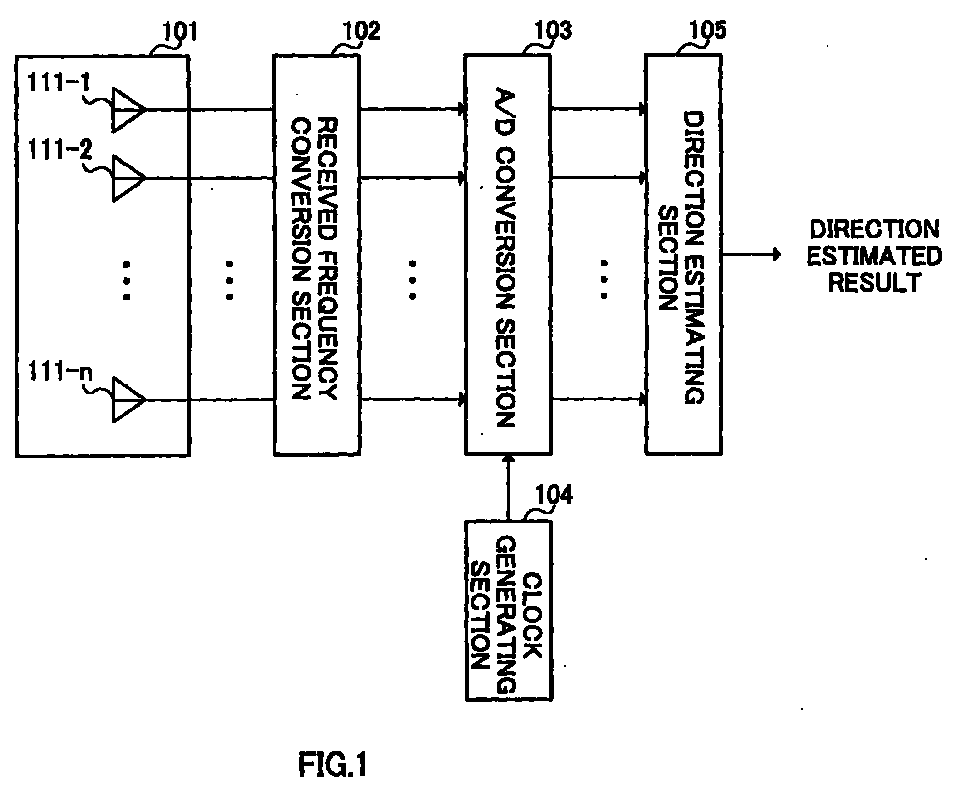
- FIG.1 is a block diagram illustrating a configuration of a direction estimating apparatus in the first embodiment of the present invention.
- the direction estimating apparatus illustrated in FIG.1 is mainly comprised of array antenna 101, received frequency conversion section 102, A/D conversion section 103 and direction estimating section 105.
- Array antenna 101 is comprised of n (n is a natural number equal to or more than 2) array elements 111-1 to 111-n. An arranged position of each of array elements 111-1 to 111-n in array antenna 101 is described later.
- Received frequency conversion section 102 converts a respective radio frequency signal received at each of array elements 111-1 to 111-n of array antenna 101 into a respective intermediate frequency signal or baseband signal.
- A/D conversion section 103 converts an analog signal output from received frequency conversion section 102 into a digital signal using a proper sampling frequency.
- Clock generating section 104 generates a clock with the sampling frequency to provide to A/D conversion section 103.
- the clock frequency generated in clock generating section 104 either of fixed or varied frequency is available.
- Direction estimating section 105 estimates directions of an incoming radio signal in a horizontal plane and vertical plane using received digital signals obtained in A/D conversion section 103.
- ⁇ is indicative of an angle in the range of 0° to 360 ° (0 to 2 ⁇ rad) in the horizontal direction
- ⁇ is indicative of an angle in the range of -90° to 90 ° (- ⁇ /2 to - ⁇ /2 rad) in the vertical direction.
- the MUSIC method calculates a covariance matrix from received signals of an array antenna, and using eigen vectors of the covariance matrix, estimates the direction of arrival.
- a covariance matrix R XX is obtained with the equation (1) shown below.
- R XX XX H
- X is a matrix having as elements respective received signals at array elements
- H is indicative of complex conjugate transposition
- - is indicative of mean.
- M eigen vectors of the covariance matrix R XX is divided into S subspace vectors E S belonging to a signal space, and (M-S) subspace vectors E N belonging to a noise space.
- the following equation (2) expresses a steering vector A( ⁇ , ⁇ ) for array antenna 101 with respect to directions ( ⁇ , ⁇ ) of the arrival signals.
- a ( ⁇ , ⁇ ) [ a 1 ( ⁇ , ⁇ ), ⁇ , a m ( ⁇ , ⁇ ), ⁇ , a M ( ⁇ , ⁇ )] T wherein m is a natural number of 1 to M, a m ( ⁇ , ⁇ ) is a steering vector for each array element, and T is indicative of transposition.
- E N and A( ⁇ 0, ⁇ 0) are orthogonalized to each other.
- an directional evaluation function F( ⁇ , ⁇ ) is expressed with the equation (3) shown below.
- F( ⁇ , ⁇ ) ⁇ A H ( ⁇ , ⁇ ) ⁇ E N ⁇ E H N ⁇ A( ⁇ , ⁇ ) ⁇ -1
- FIG.2 is a perspective view illustrating an example of arranged positions of the array elements in this embodiment when the number of array elements is 4.
- X, Y and z each is an orthogonal axis
- L is a distance between neighboring array elements on a horizontal plane
- D is a distance between neighboring array elements in the vertical direction.
- array elements 111-1 to 111-4 are arranged on a side surface of a right circular cylinder so that distance intervals on the horizontal plane are L (L>0), and concurrently distance intervals in the vertical direction are D (D>0).
- the array antenna elements 111-1 to 111-4 are arranged on a helix He.
- FIG.3A and FIG.3B illustrate diagrams to explain path differences between array elements when arrival radio signals are assumed to be plane waves in the case of FIG.2.
- FIG.3A illustrates an XY plane when a direction ( ⁇ , ⁇ ) of an arrival radio signal is ( ⁇ 1 ,0).
- the array elements 111-1 to 111-4 are arranged at equal intervals of element distance L in the form of a circle, and a center of the circle is a coordinate origin.
- path differences at array elements 111-3 and 111-4 are respectively ⁇ 1 and ⁇ 2 with respect to the coordinate origin.
- the path differences ⁇ 1 and ⁇ 2 are obtained with the equation (4) shown below.
- the path differences ⁇ 1 and ⁇ 2 are normalized with a wave length of the arrival radio signal.
- ⁇ 1 L 2sin( ⁇ /4) cos( ⁇ 1- ⁇ /4)
- ⁇ 2 L 2sin( ⁇ /4) cos( ⁇ 1-3 ⁇ /4)
- FIG.3B is a diagram illustrating an XZ plane when the direction ( ⁇ , ⁇ ) of the arrival radio signal is (0, ⁇ 1 ).
- the array elements are arranged with element distances D in the vertical direction.
- Relative path differences at array elements 111-2 and 111-4 are respectively ⁇ 1 and ⁇ 2 with respect to array element 111-3.
- the path differences ⁇ 1 and ⁇ 2 are obtained with the equation (5) shown below.
- the path differences ⁇ 1 and ⁇ 2 are normalized with the wave length of the arrival radio signal.
- a ( ⁇ , ⁇ ) [ a 1 ( ⁇ , ⁇ ), a 2 ( ⁇ , ⁇ ), a 3 ( ⁇ , ⁇ ), a 4 ( ⁇ , ⁇ )] T
- a 1 ( ⁇ , ⁇ ) exp [2 ⁇ - L 2sin( ⁇ /4) cos( ⁇ - ⁇ /4)cos ⁇ ]
- a 2 ( ⁇ , ⁇ ) exp [2 ⁇ D sin ⁇ - L 2sin( ⁇ /4) cos( ⁇ -3 ⁇ /4)cos ⁇ ]
- a 3 ( ⁇ , ⁇ ) exp [2 ⁇ 2 D sin ⁇ - L 2sin( ⁇ /4) cos( ⁇ -5 ⁇ /4)cos ⁇ ]
- a 4 ( ⁇ , ⁇ ) exp [2 ⁇ 3 D sin ⁇ - L 2sin( ⁇ /4) cos( ⁇ -7 ⁇ /4)cos ⁇ ]
- FIG.4A and FIG.4B illustrate diagrams of another example of arranged positions of array elements in this embodiment in the case where the number of array elements is M.
- FIG.4A is an XY plane
- FIG.4B is a perspective view.
- the steering vector A ( ⁇ , ⁇ ) is obtained with the equation (7) shown below.
- FIG.5A and FIG.5B are diagrams illustrating direction estimated results in the vertical direction when the number of array elements is 5, and direction estimating section 105 uses the MUSIC method as an estimation algorithm.
- FIG.5A illustrates a result in the case of using a circular array such that the array elements of array antenna 101 are arranged on the same plane in the form of a circle.
- FIG.5B illustrates another result in the case where the array elements of array antenna 101 are arranged on a helix.
- an abscissa is indicative of the vertical direction
- an ordinate is indicative of normalized level in the directional evaluation function.
- FIGs.5A and 5B illustrates a case that two arrival radio signals (P,Q) are present.
- FIG.5B has a lower normalized level K of the evaluation function at a point between the two arrival radio signals (around 0° in the vertical direction), and it is understood that arranging array elements on a helix improves the resolution.
- FIG. 6 is a diagram illustrating direction estimated results in the horizontal direction ⁇ and vertical direction ⁇ when the number of array elements is 5, the array elements are arranged on the helix, and direction estimating section 105 uses the MUSIC method as the estimation algorithm.
- FIG.6 it is possible to perform direction estimation with high resolution in the horizontal direction ⁇ and vertical direction ⁇ by arranging the array elements on the helix, and using the MUSIC method as the estimation algorithm.
- this embodiment explains the case where the array elements are arranged on the helix so that the array elements are arranged in the form of a circle on the horizontal plane. Further the present invention enables direction estimation with high resolution in the horizontal direction ⁇ and vertical direction ⁇ by arranging array elements at respective different heights from a ground so as not to overlap to each other in the vertical direction.
- FIG.7 is a block diagram illustrating a configuration of a direction estimating apparatus in this embodiment.
- sections common to those in the direction estimating apparatus illustrated in FIG.1 are assigned the same marks as those in FIG.1, and explanations thereof are omitted.
- the direction estimating apparatus illustrated in FIG.7 has position calculating section 201 in addition to configuration of the direction estimating apparatus illustrated in FIG.1.
- Direction estimating section 105 estimates directions of an incoming radio signal in the horizontal direction and vertical direction using received digital signals obtained in A/D conversion section 103, and outputs direction estimated results to position calculating section 201.
- Position calculating section 201 calculates a position of a transmission source using the direction estimated results and a height of array antenna 101.
- FIG.8 is a diagram illustrating one example of methods for calculating a position in position calculating section 201.
- H is the height of array antenna 101.
- R H/tan ⁇ 1
- position calculating section 201 is capable of specifying the position of the transmission source with R and ⁇ 1 .
- position calculating section 201 that calculates a position of a transmission source enables calculation of the position of the transmission source using the direction estimated results and the height H of array antenna 101.
- a method is conventionally known that calculates a position of a transmission-side apparatus based on a propagation delay that is a difference between a signal transmitted time at the transmission-side apparatus and a signal received time at a reception-side apparatus.
- the propagation delay of radio signals is extremely small, and the propagation environment varies due to effects of fading and noises in radio communications, whereby a measurement error in the propagation delay is large, and therefore the accuracy is limited in this method.
- the present invention estimates directions of an arrival radio signal in the horizontal direction and vertical direction, calculates a position of a transmission source based on the estimated results, and therefore provides high accuracy.
- the third embodiment explains a case that array elements are arranged so as to prevent deterioration of the estimation accuracy with respect to an arrival radio signal from a specific direction.
- a configuration of an entire apparatus is the same as that in FIG.1, and therefore the explanation thereof is omitted.
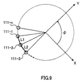
- FIG.9 is an XY plane illustrating one example of arranged positions of array elements in this embodiment.
- L1 and L2 are distances between neighboring array elements on a horizontal plane.
- the array elements of array antenna 101 are arranged on a helix so that distance intervals between neighboring array elements are ununiform on the horizontal plane.
- FIGs.10A and 10B are diagrams illustrating direction estimated results in the case of using 4 array elements, and using the MUSIC method as an estimation algorithm in direction estimating section 105.
- FIG.10A is a diagram illustrating direction estimated results in the case of arranging the array elements so that the distance intervals between neighboring array elements are constant on the horizontal plane.
- FIG.10B is a diagram illustrating another direction estimating results in the case of arranging the array elements on a helix so that the distance intervals between neighboring array elements are ununiform on the horizontal plane.
- FIGS.10A and 10B illustrates the case that a directional evaluation function F( ⁇ , ⁇ ) of an actual arrival radio signal is (90°,0°).
- the fourth embodiment explains about a directivity controlling antenna apparatus which is provided with an direction estimating apparatus according to the first embodiment, and which performs directional combining in reception using direction estimated results obtained in direction estimating section 105.
- FIG.11 is a block diagram illustrating a configuration of a directivity controlling antenna apparatus in this embodiment.
- sections common to those in the direction estimating apparatus illustrated in FIG.1 are assigned the same marks as those in FIG.1, and explanations thereof are omitted.
- the directivity controlling antenna apparatus illustrated in FIG.11 has reception weight calculating section 301 and reception beam forming section 302 in addition to the configuration of the direction estimating apparatus illustrated in FIG.1.
- Reception weight calculating section 301 obtains reception weights to control an amplitude and phase of a received signal at each array element of array antenna 101, using received digital signals output from A/D conversion section 103 and the direction estimated results output from direction estimating section 105.
- Reception beam forming section 302 performs directional combining for array antenna 101 on received digital signals output from A/D conversion section 103 using the reception weights, and outputs a desired received digital signal RX.
- the fifth embodiment explains about a directivity controlling antenna apparatus which is provided with an direction estimating apparatus according to the first embodiment, and which performs directional combining in transmission and reception using direction estimated results obtained in direction estimating section 105.
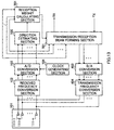
- FIG.12 is a block diagram illustrating a first configuration of the directivity controlling apparatus according to this embodiment.
- sections common to those in the directivity controlling antenna apparatus illustrated in FIG.11 are assigned the same marks as those in FIG.11, and explanations thereof are omitted.
- the directivity controlling antenna apparatus illustrated in FIG.12 has transmission weight calculating section 401, transmission beam forming section 402, D/A conversion section 403 and transmission frequency conversion section 404 in addition to the configuration of the directivity controlling antenna apparatus illustrated in FIG.12.
- Transmission weight calculating section 401 obtains transmission weights to control an amplitude and phase of a signal to be transmitted from each array element of array antenna 101, using received digital signals output from A/D conversion section 103 and the direction estimated results output from direction estimating section 105.
- Transmission beam forming section 402 performs directivity control of array antenna 101 on transmission digital signals using the transmission weights.
- D/A conversion section 403 converts an output signal from transmission beam forming section 402 into an analog transmission intermediate frequency signal or baseband signal.
- Transmission frequency conversion section 404 converts the intermediate frequency signal or baseband signal output from D/A conversion section 403 into a radio frequency signal, and the resultant radio signal is transmitted from the array antenna.
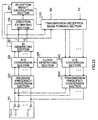
- a directivity controlling antenna apparatus is provided with transmission/reception beam forming section 501 that operates as reception beam forming section 302 and transmission beam forming section 402.
- transmission/reception beam forming section 501 performs directional combining for array antenna 101 on received digital signals output from A/D conversion section 103 using reception weights, and outputs a desired received digital signal.
- Further transmission/reception beam forming section 501 performs directivity control of array antenna 101 on transmission digital signals using the reception weights. This configuration does not require transmission weight calculating section 401, whereby it is possible to reduce a computation amount and miniaturize the apparatus.
- a directivity controlling antenna apparatus is provided with transmission array antenna 601 comprised of m array elements 611-1 to 611-m separately from array antenna 101 comprised of n (n ⁇ m) array elements, so that transmission array antenna 601 transmits a radio frequency signal output from transmission frequency conversion section 404.
- transmission array antenna 601 since it is possible to sharpen a radiation beam pattern in the direction of a desired signal in transmitting the signal, it is possible to reduce power consumption at a reception-side apparatus.
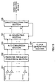
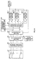
- FIG.15 is a block diagram illustrating a configuration of a direction estimating apparatus according to the sixth embodiment of the present invention.
- sections common to those in the direction estimating apparatus illustrated in FIG.1 are assigned the same marks as those in FIG.1, and explanation thereof are omitted.
- the direction estimating apparatus illustrated in FIG.15 has IQ generating section 701 in addition to the configuration of the direction estimating apparatus illustrated in FIG.1.
- A/D conversion section 103 converts an analog output signal from received frequency conversion section 102 into a digital signal using a proper sampling frequency to output to IQ generating section 701.
- IQ generating section 701 generates an in-phase component signal (hereinafter referred to as I signal) and a quadrature component signal (hereinafter referred to as Q signal) intermittently and aperiodically, using a received digital signal obtained in A/D conversion section 103, based on instruction from direction estimating section 105. In addition a specific method is described later that generates the I signal and Q signal in IQ generating section 701.
- I signal in-phase component signal
- Q signal quadrature component signal
- Direction estimating section 105 estimates a direction of arrival of a received radio signal using the I signal and Q signal output from IQ generating section 701. At this point, it is possible for direction estimating section 105 to estimate the direction of arrival of the received radio signal with high accuracy using a super resolution algorithm such as the MUSIC method. Further direction estimating section 105 instructs output timings of the I signal and Q signal to IQ generating section 701.
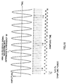
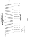
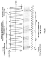
- FIGs.16 and 17 an abscissa is indicative of time, an ordinate is indicative of amplitude, and Ts is indicative of sampling period.
- a sampling frequency f s that clock generating section 104 generates is set to be 4 times the intermediate frequency f IF , a phase difference between successive two sampling points (for example, 2 and 3) is 90°. Therefore a received complex digital signal is obtained by setting a timewise former signal to be an I signal, and further setting a timewise latter signal to be a Q signal at the two successive sample points.
- a phase difference between successive two sampling points is 270°. Therefore a received complex digital signal is obtained by setting a timewise former signal to be an I signal, and further setting a timewise latter signal to be a -Q signal (which has an inverted polarity, i.e., a polarity-inverted Q signal) at the two successive sample points.
- IQ generating section 701 is capable of generating the I signals and Q signals intermittently and aperiodically.
- sampling period is set to be lower in the case of FIG.17 than that of FIG.16, it is possible to fetch the received complex digital signals more accurately, and to further improve accuracy in direction of arrival estimating processing, in the case of FIG.17.
- FIGs.16 and 17 explain the cases that the sampling frequency f s is 4 times the intermediate frequency f IF , and that the f s is 4/3 times the f IF , the present invention may obtain I signals and Q signals in a similar way to this embodiment by setting the sampling frequency f s to be 4N times or 4N/3 times the intermediate frequency f IF , and using two values in a sampling period of (N-1) (N is a natural number).
- direction estimating section 105 the direction of arrival estimating processing is performed with software operating on an OS using a PC, a time required for signal processing is indefinite, whereby it is not possible to set intervals to fetch a received signal from an array antenna to be constant.
- IQ signal generating section 701 is capable of generating I signals and Q signals intermittently and aperiodically. Therefore when direction estimating section 105 instructs IQ generating section 701 to output the I signal and Q signal at the time computation in the signal processing is completed, it is possible to generate complex digital signals aperiodically, and to perform the direction of arrival estimating processing independently of the time required for the signal processing.
- direction estimating section 105 is capable of updating a direction of arrival estimated result of a received signal sequentially every time a pair of the I signal and Q signal is obtained. Therefore it is possible to perform fast and highly accurate estimation adaptable to rapid changes in direction of arrival of a radio signal in the mobile communication environment.
- FIG.18 is a block diagram illustrating a configuration of a direction estimating apparatus in the seventh embodiment of the present invention.
- sections common to those in the direction estimating apparatus illustrated in FIG.15 are assigned the same marks as those in FIG.15, and explanations thereof are omitted.
- the direction estimating apparatus illustrated in FIG.18 has propagation environment analysis section 801, and estimation method selecting section 802 in addition to the configuration of the direction estimating apparatus illustrated in FIG.15, and further has k (k is a natural number equal to or more than 2) direction estimating sections 105-1 to 105-k.
- Propagation environment analysis section 801 measures respective levels of an I signal and Q signal output from IQ generating section 701, and based on variations in the respective levels, analyzes the propagation environment. Then propagation environment analysis section 801 outputs a signal indicative of a result analyzed from the propagation environment to estimation method selecting section 802.
- Estimation method selecting section 802 outputs the I signal and Q signal output from IQ generating section 701 to either of direction estimating sections 105-1 to 105-k, in order to enable the direction of arrival to be estimated with an optimal algorithm corresponding to the propagation environment.
- Direction estimating sections 105-1 to 105-k each estimates a direction of arrival of a received signal using an algorithm different from each other, using the I signal and Q signal output from estimation method selecting section 802.
- the eighth embodiment explains about a directivity controlling antenna apparatus which is provided with a direction estimating apparatus according to claim 6, and which performs directional combining in reception using direction estimated results obtained in direction estimating section 105.
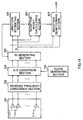
- FIG.19 is a block diagram illustrating a configuration of the directivity controlling antenna apparatus in this embodiment.
- sections common to those in the direction estimating apparatus illustrated in FIG.15 are assigned the same marks as those in FIG.15, and explanations thereof are omitted.
- the directivity controlling antenna apparatus illustrated in FIG.19 has reception weight calculating section 901 and reception beam forming section 902 in addition to the configuration of the direction estimating apparatus illustrated in FIG.15.
- Reception weight calculating section 901 obtains reception weights to control an amplitude and phase of a received signal at each array element of array antenna 101, using an I signal and Q signal output from IQ generating section 701 and the direction estimated results output from direction estimating section 105.
- Reception beam forming section 902 performs directional combining for array antenna 101 on the I signal and Q signal output from IQ generating section 701 using the reception weights, and outputs a desired received digital signal RX.
- an abscissa is indicative of time
- an ordinate is indicative of amplitude
- Ts is indicative of sampling period.
- a sampling frequency f S is set to be sufficiently higher than a symbol frequency f D of a received signal in A/D conversion section 103.
- time intervals (T IQ 1, T IQ 2,...) between the I signals and the Q signals generated in IQ generating section 701 is set to be shorter than a symbol duration, whereby demodulation processing in reception can be performed using the I signal and Q signal.
- the ninth embodiment explains about a directivity controlling antenna apparatus which is provided with a direction estimating apparatus according to the sixth embodiment, and which performs directional combining in transmission and reception using direction estimated results obtained in direction estimating section 105.
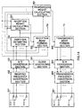
- FIG.21 is a block diagram illustrating a first configuration of the directivity controlling antenna apparatus according to this embodiment.
- sections common to those in the directivity controlling apparatus illustrated in FIG.19 are assigned the same marks as those in FIG.19, and explanations thereof are omitted.
- the directivity controlling antenna apparatus illustrated in FIG.21 has transmission weight calculating section 1001, transmission beam forming section 1002, D/A conversion section 1003 and transmission frequency conversion section 1004 in addition to the configuration of the directivity controlling antenna apparatus illustrated in FIG.19.
- Transmission weight calculating section 1001 obtains transmission weights to control an amplitude and phase of a signal to be transmitted from each array element of array antenna 101, using an I signal and Q signal output from IQ generating section 701 and the direction estimated results output from direction estimating section 105.
- Transmission beam forming section 1002 performs directivity control of array antenna 101 on transmission digital signals using the transmission weights.
- D/A conversion section 1003 converts an output signal from transmission beam forming section 1002 into an analog transmission intermediate frequency signal or baseband signal.
- Transmission frequency conversion section 1004 converts the intermediate frequency signal or baseband signal output from D/A conversion section 403 into a radio frequency signal, and the resultant radio signal is transmitted from the array antenna.
- a directivity controlling antenna apparatus is provided with transmission/reception beam forming section 1101 that operates as reception beam forming section 902 and transmission beam forming section 1002.
- transmission/reception beam forming section 1101 performs directional combining for array antenna 101 on the I signal and Q signal output from IQ generating section 701 using reception weights, and outputs a desired received digital signal.
- Further transmission/reception beam forming section 1101 performs directivity control of array antenna 101 on transmission digital signals using the reception weights. This configuration does not require transmission weight calculating section 1002, whereby it is possible to reduce a computation amount and miniaturize the apparatus.
- a directivity controlling antenna apparatus is provided with transmission array antenna 1201 comprised of m array elements 1211-1 to 1211-m separately from array antenna 101 comprised of n (n ⁇ m) array elements, so that transmission array antenna 601 transmits a radio frequency signal output from transmission frequency conversion section 1104.
- transmission array antenna 1201 comprised of m array elements 1211-1 to 1211-m separately from array antenna 101 comprised of n (n ⁇ m) array elements, so that transmission array antenna 601 transmits a radio frequency signal output from transmission frequency conversion section 1104.
- the present invention by arranging array elements of an array antenna at respective heights different from each other from a ground so as not to overlap to each other in the vertical direction, it is possible to improve direction estimation accuracy in the vertical direction and resolution as compared to the case that the array elements are arranged in the form of a circle on the same plane. Further it is possible to calculate a position of a transmission source by using the estimated results, and furthermore to obtain effects such as improved communication qualities and reduced power consumption by controlling the directivity of the array antenna.
Landscapes
- Physics & Mathematics (AREA)
- Engineering & Computer Science (AREA)
- General Physics & Mathematics (AREA)
- Radar, Positioning & Navigation (AREA)
- Remote Sensing (AREA)
- Variable-Direction Aerials And Aerial Arrays (AREA)
- Radio Transmission System (AREA)
Abstract
Description
Claims (16)
- An direction estimating apparatus comprising:an array antenna (101) using a plurality of antennas as array elements (111-1∼n), said array elements being arranged at respective different heights from a ground so as not to overlap to each other in a vertical direction;received frequency conversion means (102) for converting a radio frequency signal received at each of the array elements into an intermediate frequency signal or a baseband signal;A/D conversion means (103) for converting an analog signal output from the received frequency conversion means into a digital signal; anddirection estimating means (105) for estimating a horizontal direction and a vertical direction of an arrival radio signal using the digital signal output from the A/D conversion means.
- The direction estimating apparatus according to claim 1, wherein each of the array elements of the array antenna is arranged on a helix.
- The direction estimating apparatus according to claim 2, wherein each of the array elements of the array antenna is arranged so that neighboring array elements are arranged at equal intervals on a horizontal plane.
- The direction estimating apparatus according to claim 2, wherein each of the array elements of the array antenna is arranged so that intervals between neighboring array elements are ununiform on a horizontal plane.
- The direction estimating apparatus according to claim 1, further comprising:position calculating means (201) for calculating a position of a transmission source based on the horizontal direction and vertical direction of the arrival radio signal estimated in the direction estimating means.
- A directivity controlling antenna apparatus comprising:a first array antenna (101) using a plurality of antennas as array elements (111-1 ∼ n), said array elements being arranged at respective different heights from a ground so as not to overlap to each other in a vertical direction;received frequency conversion means (102) for converting a radio frequency signal received at each of the array elements into an intermediate frequency signal or a baseband signal;A/D conversion means (103) for converting an analog signal output from the received frequency conversion means into a digital signal;direction estimating means (105) for estimating a horizontal direction and a vertical direction of an arrival radio signal using the digital signal output from the A/D conversion means;reception weight calculating means (301) for obtaining a reception weight based on the digital signal and the horizontal direction and vertical direction of the arrival radio signal estimated in the direction estimating means; andreception beam forming means (302) for performing directional combining for the first array antenna using the reception weight obtained in the reception weight calculating means.
- The directivity controlling antenna apparatus according to claim 6, further comprising:transmission weight calculating means (401) for obtaining a transmission weight based on the digital signal and the horizontal direction and vertical direction of the arrival radio signal;transmission beam forming means (402) for performing weighting on a transmission digital signal using the transmission weight obtained in the transmission weight calculating means;D/A conversion means (403) for converting a weighted transmission digital signal into an analog signal; andtransmission frequency conversion means (404) for converting an intermediate frequency signal or a baseband signal output from the D/A conversion means into a radio frequency signal to transmit.
- The directivity controlling antenna apparatus according claim 6, further comprising:D/A conversion means (403) for converting a weighted transmission digital signal into an analog signal;transmission frequency conversion means (404) for converting an intermediate frequency signal or a baseband signal output from the D/A conversion means into a radio frequency signal to transmit, and
wherein the reception beam forming means (501) performs weighting on a transmission digital signal using the reception weight. - The directivity controlling antenna apparatus according claim 7, further comprising:a second array antenna (601) comprised of array elements (611-1∼n) of which the number is larger than the number of array elements of the first array antenna, and
wherein the transmission frequency conversion means (404) transmits the radio frequency signal from said second array antenna. - The direction estimating apparatus according claim 1, further comprising:IQ generating means (701) for generating an in-phase component signal and a quadrature component signal intermittently and aperiodically from the digital signal output from the A/D conversion means; and
wherein the direction estimating means (105) estimates the horizontal direction and the vertical direction of the arrival radio signal using the in-phase component signal and the quadrature component signal output from said IQ generating means. - The direction estimating apparatus according claim 10, wherein the A/D conversion means (103) converts the analog signal output from the received frequency conversion means into the digital signal using a sampling frequency 4N (N is a natural number) times an intermediate frequency, and the IQ generating means (701) sets two successive sampled signals at sampling intervals of (N-1) to be the in-phase component signal and the quadrature component signal.
- The direction estimating apparatus according claim 10, wherein the A/D conversion means (103) converts the analog signal output from the received frequency conversion means into the digital signal using a sampling frequency 4N/3 (N is a natural number) times an intermediate frequency, and the IQ generating means (701) sets two successive sampled signals at sampling intervals of (N-1) to be the in-phase component signal and a polarity-inverted quadrature component signal.
- The direction estimating apparatus according to claim 10, wherein the direction estimating means (105) updates estimated results of the horizontal direction and the vertical direction of the arrival radio signal every time the IQ generating means generates a pair of the in-phase component signal and the quadrature component signal.
- The direction estimating apparatus according to claim 10, further comprising:propagation environment analysis means (801) for measuring respective levels of the in-phase component signal and the quadrature component signal, and based on variations in the respective levels, analyzing a propagation environment;estimation method selecting means (802) for selecting an optimal direction of arrival estimating algorithm corresponding to the propagation environment analyzed in the propagation environment analysis means, and
wherein the direction estimating means (105-1∼n) estimates the horizontal direction and the vertical direction of the arrival radio signal using the direction of arrival estimating algorithm selected in the estimation method selecting means. - A directivity controlling antenna apparatus comprising:a third array antenna (101) using a plurality of antennas as array elements(111-1∼n);received frequency conversion means (102) for converting a radio frequency signal received at each of the array elements into an intermediate frequency signal or a baseband signal;A/D conversion means (103) for converting an analog signal output from the received frequency conversion means into a digital signal;IQ generating means (701) for generating an in-phase component signal and a quadrature component signal intermittently and aperiodically from the digital signal output from A/D conversion means; anddirection estimating means (105) for estimating a horizontal direction and a vertical direction of an arrival radio signal using the in-phase component signal and the quadrature component signal output from said IQ generating means;reception weight calculating means (901) for obtaining a reception weight based on the horizontal direction and the vertical direction of the arrival radio signal estimated in the direction estimating means and the digital signal; andreception beam forming means (902) for performing directional combining for the third array antenna using the reception weight obtained in the reception weight calculating means.
- An direction estimating method, comprising:arranging a plurality of antennas composing an array antenna at respective different heights from a ground so as not to overlap to each other in a vertical direction; andestimating a horizontal direction and a vertical direction of an arrival radio signal using a signal received at each of the antennas.
Applications Claiming Priority (4)
| Application Number | Priority Date | Filing Date | Title |
|---|---|---|---|
| JP23673299 | 1999-08-24 | ||
| JP23673299 | 1999-08-24 | ||
| JP2000242961 | 2000-08-10 | ||
| JP2000242961A JP4925502B2 (en) | 2000-08-10 | 2000-08-10 | Array antenna, azimuth estimation apparatus, communication apparatus, and azimuth estimation method |
Publications (2)
| Publication Number | Publication Date |
|---|---|
| EP1079461A2 true EP1079461A2 (en) | 2001-02-28 |
| EP1079461A3 EP1079461A3 (en) | 2002-08-14 |
Family
ID=26532820
Family Applications (1)
| Application Number | Title | Priority Date | Filing Date |
|---|---|---|---|
| EP00118320A Withdrawn EP1079461A3 (en) | 1999-08-24 | 2000-08-23 | Direction estimating apparatus, directivity controlling antenna apparatus, and direction estimating method |
Country Status (2)
| Country | Link |
|---|---|
| US (1) | US6333713B1 (en) |
| EP (1) | EP1079461A3 (en) |
Cited By (6)
| Publication number | Priority date | Publication date | Assignee | Title |
|---|---|---|---|---|
| GB2356740B (en) * | 1999-09-24 | 2003-11-19 | Fujitsu Ltd | Communication device with adaptive antenna |
| EP1178567A3 (en) * | 2000-08-02 | 2004-12-08 | Matsushita Electric Industrial Co., Ltd. | Circular array antenna and method of using the same |
| WO2005050783A1 (en) * | 2003-10-30 | 2005-06-02 | Telecom Italia S.P.A. | Method and system for performing digital beam forming at intermediate frequency on the radiation pattern of an array antenna |
| EP1584943A3 (en) * | 2004-04-10 | 2006-06-28 | Ewation GmbH | High resolution direction finding method with broad band FFT sensors |
| DE102006036940B3 (en) * | 2006-08-08 | 2008-04-10 | Bruno Dr. Demissie | Parameter determination method for position data processing of local variable sources with regular array antennas involves computing signal area and white noise area at antenna outputs by maximizing preset direction finding function |
| CN107844126A (en) * | 2016-09-20 | 2018-03-27 | 卡西欧计算机株式会社 | Direction estimation device, direction determining method, flight instruments, flying method and recording medium |
Families Citing this family (11)
| Publication number | Priority date | Publication date | Assignee | Title |
|---|---|---|---|---|
| JP2001305202A (en) * | 2000-04-24 | 2001-10-31 | Toyota Central Res & Dev Lab Inc | MUSIC spectrum calculation method, apparatus and medium |
| JP2002084217A (en) * | 2000-09-08 | 2002-03-22 | Matsushita Electric Ind Co Ltd | Base station apparatus and arrival direction estimation method |
| US7006040B2 (en) * | 2000-12-21 | 2006-02-28 | Hitachi America, Ltd. | Steerable antenna and receiver interface for terrestrial broadcast |
| JPWO2003073649A1 (en) * | 2002-02-28 | 2005-06-23 | 三洋電機株式会社 | Wireless device, wireless device calibration system, calibration method, and calibration program |
| GB0300352D0 (en) * | 2003-01-08 | 2003-02-05 | Secr Defence | Radio signal direction finder |
| US7706324B2 (en) * | 2004-07-19 | 2010-04-27 | Qualcomm Incorporated | On-demand reverse-link pilot transmission |
| WO2007101451A1 (en) * | 2006-03-09 | 2007-09-13 | Fundacio Privada Centre Tecnologic De Telecomunicacions De Catalunya | Method and system for estimating directions-of-arrival in low power or low sample size scenarios |
| US8774837B2 (en) | 2011-04-30 | 2014-07-08 | John Anthony Wright | Methods, systems and apparatuses of emergency vehicle locating and the disruption thereof |
| JP6924046B2 (en) * | 2017-03-08 | 2021-08-25 | 株式会社デンソーテン | Radar device and elevation estimation method |
| US10708876B2 (en) * | 2017-03-23 | 2020-07-07 | Legic Identsystem Ag | System and method for determining location information for a mobile radio transmitter |
| CN110221242B (en) * | 2019-05-20 | 2021-07-02 | 北京航空航天大学 | A UAV detection method based on time-modulated array |
Family Cites Families (12)
| Publication number | Priority date | Publication date | Assignee | Title |
|---|---|---|---|---|
| US3903522A (en) | 1971-02-08 | 1975-09-02 | Texas Instruments Inc | Direction-finding system having slope control means |
| JPH04177946A (en) * | 1990-11-09 | 1992-06-25 | Sony Corp | Digital demodulator |
| US5327143A (en) | 1992-06-22 | 1994-07-05 | Trw Inc. | Multiple arm spiral antenna system with multiple beamforming capability |
| EP0687031A2 (en) * | 1992-10-19 | 1995-12-13 | Nortel Networks Corporation | Base station antenna arrangement |
| US5317323A (en) * | 1993-03-05 | 1994-05-31 | E-Systems, Inc. | Passive high accuracy geolocation system and method |
| US5371506A (en) * | 1993-07-19 | 1994-12-06 | General Electric Co. | Simultaneous multibeam approach for cancelling multiple mainlobe jammers while preserving monopulse angle estimation accuracy on mainlobe targets |
| GB2309858B (en) * | 1996-01-31 | 2000-08-23 | Motorola Ltd | Apparatus and method for channel allocation |
| JPH09238009A (en) * | 1996-03-01 | 1997-09-09 | Mitsubishi Electric Corp | Circular array antenna |
| JP3204111B2 (en) * | 1996-08-28 | 2001-09-04 | 松下電器産業株式会社 | Directivity control antenna device |
| JPH10117220A (en) * | 1996-10-11 | 1998-05-06 | Hitachi Denshi Ltd | Digital demodulator |
| GB9623558D0 (en) * | 1996-11-12 | 1997-01-08 | Secr Defence | Antenna array |
| JP2000065911A (en) | 1998-08-17 | 2000-03-03 | Nec Corp | Method for detecting arrival azimuth of radio wave and apparatus for detecting arrival azimuth of radio wave |
-
2000
- 2000-08-17 US US09/639,996 patent/US6333713B1/en not_active Expired - Lifetime
- 2000-08-23 EP EP00118320A patent/EP1079461A3/en not_active Withdrawn
Cited By (8)
| Publication number | Priority date | Publication date | Assignee | Title |
|---|---|---|---|---|
| GB2356740B (en) * | 1999-09-24 | 2003-11-19 | Fujitsu Ltd | Communication device with adaptive antenna |
| EP1178567A3 (en) * | 2000-08-02 | 2004-12-08 | Matsushita Electric Industrial Co., Ltd. | Circular array antenna and method of using the same |
| US7031719B2 (en) | 2000-08-02 | 2006-04-18 | Matsushita Electric Industrial Co., Ltd. | Method of calculating exciting coefficients for circular array antenna and radio unit utilizing the same |
| WO2005050783A1 (en) * | 2003-10-30 | 2005-06-02 | Telecom Italia S.P.A. | Method and system for performing digital beam forming at intermediate frequency on the radiation pattern of an array antenna |
| US7403156B2 (en) | 2003-10-30 | 2008-07-22 | Telecon Italia S.P.A. | Method and system for performing digital beam forming at intermediate frequency on the radiation pattern of an array antenna |
| EP1584943A3 (en) * | 2004-04-10 | 2006-06-28 | Ewation GmbH | High resolution direction finding method with broad band FFT sensors |
| DE102006036940B3 (en) * | 2006-08-08 | 2008-04-10 | Bruno Dr. Demissie | Parameter determination method for position data processing of local variable sources with regular array antennas involves computing signal area and white noise area at antenna outputs by maximizing preset direction finding function |
| CN107844126A (en) * | 2016-09-20 | 2018-03-27 | 卡西欧计算机株式会社 | Direction estimation device, direction determining method, flight instruments, flying method and recording medium |
Also Published As
| Publication number | Publication date |
|---|---|
| EP1079461A3 (en) | 2002-08-14 |
| US6333713B1 (en) | 2001-12-25 |
Similar Documents
| Publication | Publication Date | Title |
|---|---|---|
| US6333713B1 (en) | Direction estimating apparatus, directivity controlling antenna apparatus, and direction estimating method | |
| JP3985883B2 (en) | Radio wave arrival direction estimation antenna device | |
| Li et al. | Angle-of-arrival estimation for localization and communication in wireless networks | |
| Garcia et al. | POLAR: Passive object localization with IEEE 802.11 ad using phased antenna arrays | |
| KR20160014107A (en) | Configuring antenna arrays of mobile wireless devices using motion sensors | |
| JP2013055663A (en) | Beam formation apparatus and beam formation method for antenna | |
| US6501943B1 (en) | Adaptive directivity transmission device and method | |
| US11502406B2 (en) | Phased array orientation finding method | |
| Rao et al. | MSDFL: a robust minimal hardware low-cost device-free WLAN localization system | |
| Celik et al. | Implementation and experimental verification of hybrid smart-antenna beamforming algorithm | |
| EP3120417B1 (en) | Method for finding signal direction using modal antenna | |
| Baig et al. | Joint communication and sensing beamforming for passive object localization | |
| JP4166401B2 (en) | Reception directivity control method, antenna apparatus, and mobile communication base station and mobile station using the same | |
| Werner et al. | Primary user localization in cognitive radio networks using sectorized antennas | |
| Taillefer et al. | Reactance-domain MUSIC for ESPAR antennas (experiment) | |
| JP4065802B2 (en) | Mobile station, communication control method | |
| CN101330304B (en) | Method and device for calculating arrival direction in an intelligent antenna system | |
| JP4925502B2 (en) | Array antenna, azimuth estimation apparatus, communication apparatus, and azimuth estimation method | |
| JP2004336390A (en) | Adaptive array and positioning device | |
| JP4119719B2 (en) | Mobile station direction estimation method and apparatus | |
| WO1998018018A1 (en) | Determining direction of a mobile terminal in a cellular communication system | |
| JP4660562B2 (en) | Mobile station direction estimation method and apparatus | |
| JP3640873B2 (en) | Direction estimation apparatus, directivity control antenna apparatus, and direction estimation method | |
| Jami et al. | Improved method for estimating angle of arrival in multipath conditions using the'MUSIC'algorithm | |
| JPH1075110A (en) | Transmit beamforming method |
Legal Events
| Date | Code | Title | Description |
|---|---|---|---|
| PUAI | Public reference made under article 153(3) epc to a published international application that has entered the european phase |
Free format text: ORIGINAL CODE: 0009012 |
|
| AK | Designated contracting states |
Kind code of ref document: A2 Designated state(s): AT BE CH CY DE DK ES FI FR GB GR IE IT LI LU MC NL PT SE |
|
| AX | Request for extension of the european patent |
Free format text: AL;LT;LV;MK;RO;SI |
|
| PUAL | Search report despatched |
Free format text: ORIGINAL CODE: 0009013 |
|
| RIC1 | Information provided on ipc code assigned before grant |
Free format text: 7H 01Q 3/26 A, 7G 01S 3/74 B, 7H 04Q 7/36 B, 7H 03D 3/00 B |
|
| AK | Designated contracting states |
Kind code of ref document: A3 Designated state(s): AT BE CH CY DE DK ES FI FR GB GR IE IT LI LU MC NL PT SE |
|
| AX | Request for extension of the european patent |
Free format text: AL;LT;LV;MK;RO;SI |
|
| 17P | Request for examination filed |
Effective date: 20020927 |
|
| 17Q | First examination report despatched |
Effective date: 20021211 |
|
| AKX | Designation fees paid |
Designated state(s): DE FR GB |
|
| 17Q | First examination report despatched |
Effective date: 20021211 |
|
| STAA | Information on the status of an ep patent application or granted ep patent |
Free format text: STATUS: THE APPLICATION IS DEEMED TO BE WITHDRAWN |
|
| 18D | Application deemed to be withdrawn |
Effective date: 20080301 |