EP1079460A2 - Glass antenna device - Google Patents
Glass antenna device Download PDFInfo
- Publication number
- EP1079460A2 EP1079460A2 EP00307253A EP00307253A EP1079460A2 EP 1079460 A2 EP1079460 A2 EP 1079460A2 EP 00307253 A EP00307253 A EP 00307253A EP 00307253 A EP00307253 A EP 00307253A EP 1079460 A2 EP1079460 A2 EP 1079460A2
- Authority
- EP
- European Patent Office
- Prior art keywords
- antenna device
- coaxial cable
- ground pattern
- pattern
- antenna
- Prior art date
- Legal status (The legal status is an assumption and is not a legal conclusion. Google has not performed a legal analysis and makes no representation as to the accuracy of the status listed.)
- Withdrawn
Links
- 239000011521 glass Substances 0.000 title claims abstract description 23
- 239000004020 conductor Substances 0.000 claims abstract description 22
- 230000005855 radiation Effects 0.000 claims abstract description 15
- 230000000052 comparative effect Effects 0.000 description 6
- 230000008878 coupling Effects 0.000 description 3
- 238000010168 coupling process Methods 0.000 description 3
- 238000005859 coupling reaction Methods 0.000 description 3
- 230000003247 decreasing effect Effects 0.000 description 2
- 239000005357 flat glass Substances 0.000 description 2
- 239000000463 material Substances 0.000 description 2
- 238000005476 soldering Methods 0.000 description 2
- 230000000007 visual effect Effects 0.000 description 2
- 230000000694 effects Effects 0.000 description 1
- 238000010295 mobile communication Methods 0.000 description 1
Images



Classifications
-
- H—ELECTRICITY
- H01—ELECTRIC ELEMENTS
- H01Q—ANTENNAS, i.e. RADIO AERIALS
- H01Q1/00—Details of, or arrangements associated with, antennas
- H01Q1/12—Supports; Mounting means
- H01Q1/1271—Supports; Mounting means for mounting on windscreens
Definitions
- the present invention relates to a glass antenna device for vehicles, particularly to a feeding structure in the glass antenna device.
- Glass antenna devices mounted on a vehicle window have been used widely to receive amplitude modulation waves or frequency modulation waves. Furthermore, glass antennas are beginning to be used as well as rod antennas for mobile communications (automobile telephones).
- Fig. 8 shows a conventional antenna device 101 for automobile telephones (e.g. for an 800 MHz band).
- the antenna device 101 comprises antenna patterns 111 and 112 formed on a rear window glass 105, a coaxial cable 102, and a receiver/transmitter (not shown).
- the substantially linear radiation pattern 111 is connected to a core 121 that is the inner conductor of the coaxial cable 102. Furthermore, the ground pattern 112 is arranged so that its one edge becomes parallel to and in close proximity to the vehicle body 104, so that it can be coupled capacitively with the vehicle body 104. Furthermore, a braided wire that is the outer conductor of the coaxial cable is connected and fixed to the ground pattern with a presser metallic terminal 103. Thus, the antenna device is grounded to the vehicle body 104 via the ground pattern.
- grounding by the ground pattern is not perfect.
- a potential difference may be generated between the ground pattern and the coaxial cable.
- a current may flow from the ground pattern to the coaxial cable. This current causes radiation of waves from the coaxial cable. That is, the coaxial cable acts like an antenna.
- the antenna performance changes when the coaxial cable is turned around, that is the position of the coaxial cable is changed, as if the antenna itself is moved.
- JP-A-6-53721 discloses a connecting structure of a glass antenna, particularly a structure in which the outer conductor of a coaxial cable is connected to a ring by soldering.
- JP-A-8-130404 also discloses another connecting structure of a glass antenna.
- the glass antennas disclosed in the above-mentioned publications have good electrical connections.
- positioning the coaxial cable in a vehicle may be restricted depending on the vehicle shape or the location at which the antenna device is mounted.
- the antenna performance may become poor with the turning that is allowed.
- the present invention provides a glass antenna device mounted on a fixed window of a vehicle, comprising a radiation conductor pattern and a ground conductor pattern, the radiation pattern being connected to an inner conductor of a coaxial cable, the ground pattern being coupled capacitively with a body of the vehicle and further being connected to an outer conductor of the coaxial cable in at least two connecting portions.
- the distance between two adjacent connecting portions is at least ⁇ /4, where ⁇ is a wavelength that is received or transmitted by the antenna device.
- ⁇ is a wavelength that is received or transmitted by the antenna device.
- the number of the connecting portions is two.
- an increase in the number of the assembly steps resulting from the increased connecting portions can be minimized, while the stability in the antenna performance is ensured.
- the number of the connecting portions is three.
- an antenna device can be provided in which the potential coupling between the ground pattern and the coaxial cable is further ensured, and in which the antenna performance is further stabilized.
- the ground pattern has a length of at least ⁇ /2, where ⁇ is a wavelength that is received or transmitted by the antenna device.
- the present invention is characterized in that the ground pattern is connected to the outer conductor of the coaxial cable in at least two connecting portions.
- This structure can ensure potential coupling between the ground pattern and the coaxial cable, so that the influence of the imperfect grounding by the ground pattern can be reduced. Moreover, by making the distance between the adjacent connecting portions at least ⁇ /4, the influence of the imperfect grounding can be further reduced.
- the present invention has an effect that the antenna performance is not affected by the position at which the coaxial cable is laid in a vehicle.
- the region of the coaxial cable from the last of the connecting portions can be positioned without particular restrictions.
- the glass antenna device can be mounted to a vehicle regardless of the vehicle design or the location at which it is mounted.
- the last connecting portion herein refers to the connecting portion that is the farthest from the radiation pattern.
- the distance between the adjacent connecting portions is less than ⁇ /4, the potential of the ground pattern might be increased, which may lead to difficulty in feeding.
- the distance between the adjacent connecting portions is at least ⁇ /4.
- Fig. 1 is a plan view showing a first embodiment of the antenna device according to the present invention.
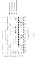
- Fig. 2 is a graph showing the change in the antenna performance.
- Fig. 3 is a plan view showing a second embodiment of the antenna device according to the present invention.
- Fig. 4 is a plan view showing a third embodiment of the antenna device according to the present invention.
- Fig. 5 is a plan view showing an application example of the first embodiment of the antenna device according to the present invention.
- Fig. 6 is a plan view showing another application example of the first embodiment of the antenna device according to the present invention.
- Fig. 7 is a plan view showing an application example of the second embodiment of the antenna device according to the present invention.
- Fig. 8 is a plan view showing a conventional antenna device for automobile telephones.
- Fig. 1 is a schematic illustration of an antenna device 1 that is a first embodiment of the present invention.
- An antenna device 1 is mounted along the lower edge of a rear window glass 5.
- a radiation conductor pattern 11 is a linear pattern having a length of substantially ⁇ /4, and is connected to a core 21 that is the inner conductor of a coaxial cable 2.
- a ground conductor pattern 12 is a band-shaped pattern that has a relieved portion (a recessed portion) surrounding an edge portion of the radiation pattern 11. The ground pattern has a length of substantially ⁇ /2, where ⁇ is the center wavelength that is received and transmitted.
- the wavelength ⁇ is about 400 mm in the case of an 800 MHz band, and about 200 mm in the case of a 1.5 GHz band.
- the ground pattern 12 and a braided wire that is the outer conductor of the coaxial cable 2 are connected and fixed with two metallic terminals 3, 3 spaced at a distance L of substantially ⁇ /4.
- the metallic terminals 3, 3 are soldered to the ground pattern 12.
- the outer sheath of the coaxial cable is peeled off in the portions corresponding to the metallic terminals 3, 3 so that it is electrically connected to the metallic terminals 3, 3.
- the coaxial cable 2 is connected to a receiver and transmitter, which is not shown in the drawing.
- Fig. 2 shows changes in VSWR (absolute value) when the coaxial cable was moved. Also shown in this graph are those of second and third embodiments and a comparative example below.
- the change in the antenna performance can be decreased.
- change in the antenna performance can be decreased when the spacing between the connecting portions is substantially ⁇ /4.
- Fig. 3 shows an antenna device of a second embodiment of the present invention.
- this second embodiment half of the ground pattern of the first embodiment was removed, and other features were the same as in the first embodiment.
- a comparison between the results of the first and second embodiments shows that it is preferable that the ground pattern has a length of substantially ⁇ /2 or longer in terms of antenna performance.
- Fig. 4 shows an antenna device of a third embodiment of the present invention.
- This third embodiment is an example having three connecting portions.
- a ground pattern 12 and a braided wire that is the outer conductor of a coaxial cable 2 are connected and fixed with three metallic terminals 3.
- Each of the spaces L and L' is substantially ⁇ /4.
- a comparison between the results of the second and third embodiments shows that it is preferable that the number of the connecting portions is three rather than two in terms of antenna performance.
- the ground pattern has a length of substantially ⁇ /2 or longer in terms of antenna performance.
- Fig. 5 shows an antenna device that is an application example of the first embodiment of the present invention.
- the ground pattern 12 is mounted along a side edge of a glass plate 5, although the ground pattern 12 of the above first embodiment was mounted along the lower edge of the glass plate.
- the radiation pattern 11 has a T-shape.
- Fig. 6 shows an antenna device that is another application example of the first embodiment of the present invention.
- the ground pattern 12 is mounted along a corner between the lower edge and a side edge of a glass plate, and has substantially an L-shape.
- Fig. 7 shows an antenna device that is an application example of the second embodiment of the present invention.
- the ground pattern 12 also is mounted along a side edge of a glass plate.
- the radiation pattern 11 has substantially an L-shape.
- the radiation pattern 111 is a linear pattern having a length of substantially ⁇ /4 and is connected to the core 121 that is the inner conductor of the coaxial cable 102.
- the ground pattern 112 is a rectangular pattern having a vertical length of substantially ⁇ /4 and a horizontal length of substantially ⁇ /2.
- the ground pattern 112 and a braided wire that is the outer conductor of the coaxial cable 102 are connected and fixed with a single metallic terminal 103. Furthermore, the metallic terminal 103 is soldered to the ground pattern 112.
- the present invention has been described with reference to the above embodiments.
- the shape of the radiation pattern is not particularly limited as long as it can transmit and receive the waves of intended wavelengths.
- At least the ground pattern is substantially band-shaped and has a sufficient width that enables the attachment of the metallic terminals so as to connect the ground pattern to the coaxial cable. If the width of the ground pattern is too large, the cost of the pattern material will be increased, and in addition, it will become a visual obstruction. Thus, it is desired that the width is kept within a suitable range.
- the length L of the ground pattern is preferably at least larger than ⁇ /4. It is more preferable that the length L is at least ⁇ /2. Moreover, although there is no particular upper limit, if the length of the ground pattern is too large, the cost of the pattern material will increase, and in addition, it will become a visual obstruction. Thus, it is desired that the length is kept within a suitable range, particularly within the range of L ⁇ ⁇ .
Landscapes
- Details Of Aerials (AREA)
Abstract
Description
Claims (5)
- A glass antenna device (1) mounted on a fixed window (5) of a vehicle, comprising a radiation conductor pattern (11) and a ground conductor pattern (12),the radiation pattern being connected to an inner conductor (21) of a coaxial cable (2),the ground pattern being coupled capacitively with a body (4) of the vehicle and further being connected to an outer conductor of the coaxial cable in at least two connecting portions (3).
- The glass antenna device according to claim 1, wherein the distance (L) between two adjacent connecting portions is at least λ/4, where λ is a wavelength that is received or transmitted by the antenna device.
- The glass antenna device according to claim 1 or 2, wherein the number of the connecting portions is two.
- The glass antenna device according to claim 1 or 2, wherein the number of the connecting portions is three.
- The glass antenna device according to any peceding claim, wherein the ground pattern (12) has a length of at least λ/2, where λ is a wavelength that is received or transmitted by the antenna device.
Applications Claiming Priority (2)
| Application Number | Priority Date | Filing Date | Title |
|---|---|---|---|
| JP23560499 | 1999-08-23 | ||
| JP23560499 | 1999-08-23 |
Publications (2)
| Publication Number | Publication Date |
|---|---|
| EP1079460A2 true EP1079460A2 (en) | 2001-02-28 |
| EP1079460A3 EP1079460A3 (en) | 2002-05-15 |
Family
ID=16988479
Family Applications (1)
| Application Number | Title | Priority Date | Filing Date |
|---|---|---|---|
| EP00307253A Withdrawn EP1079460A3 (en) | 1999-08-23 | 2000-08-23 | Glass antenna device |
Country Status (3)
| Country | Link |
|---|---|
| US (1) | US6292150B1 (en) |
| EP (1) | EP1079460A3 (en) |
| CA (1) | CA2316597A1 (en) |
Cited By (1)
| Publication number | Priority date | Publication date | Assignee | Title |
|---|---|---|---|---|
| WO2005027260A3 (en) * | 2003-09-15 | 2005-06-02 | Harada Ind Co Ltd | Integrated antenna with coupled ground |
Families Citing this family (10)
| Publication number | Priority date | Publication date | Assignee | Title |
|---|---|---|---|---|
| DE20202334U1 (en) | 2002-02-14 | 2002-06-06 | FUBA Automotive GmbH & Co. KG, 31162 Bad Salzdetfurth | Automobile antennas |
| DE20219770U1 (en) * | 2002-12-20 | 2004-01-15 | Pilkington Automotive Deutschland Gmbh | Car windscreen antenna has broadcast antenna wire and multiple wire combined earth radial and heater with capacitive coupling and stub tuning option |
| JP2004242153A (en) * | 2003-02-07 | 2004-08-26 | Honda Motor Co Ltd | In-vehicle antenna |
| US7154444B2 (en) * | 2003-04-04 | 2006-12-26 | General Motors Corporation | Ground plane compensation for mobile antennas |
| JP2010206772A (en) * | 2009-02-06 | 2010-09-16 | Central Glass Co Ltd | Glass antenna |
| US9385422B2 (en) * | 2010-05-19 | 2016-07-05 | Saint-Gobain Glass France | Antenna bandwidth-optimized by hybrid structure comprising planar and linear emitters |
| EP2400591A1 (en) * | 2010-06-14 | 2011-12-28 | Saint-Gobain Glass France | Antenna structure with improved signal/noise ratio |
| JP5707501B2 (en) * | 2011-09-26 | 2015-04-30 | 株式会社フジクラ | ANTENNA DEVICE AND ANTENNA MOUNTING METHOD |
| US10243251B2 (en) * | 2015-07-31 | 2019-03-26 | Agc Automotive Americas R&D, Inc. | Multi-band antenna for a window assembly |
| CN117144340B (en) * | 2022-05-24 | 2025-08-26 | 江苏微导纳米科技股份有限公司 | Winding processing equipment |
Family Cites Families (13)
| Publication number | Priority date | Publication date | Assignee | Title |
|---|---|---|---|---|
| JPS61174208U (en) * | 1985-04-18 | 1986-10-30 | ||
| US5293174A (en) * | 1987-05-21 | 1994-03-08 | Kropielnicki Jerzy J | Vehicle antenna |
| DE3907493A1 (en) * | 1989-03-08 | 1990-09-20 | Lindenmeier Heinz | DISC ANTENNA WITH ANTENNA AMPLIFIER |
| DE3911178A1 (en) * | 1989-04-06 | 1990-10-11 | Lindenmeier Heinz | WINDOW ANTENNA SYSTEM WITH ANTENNA AMPLIFIER |
| JPH045064U (en) * | 1990-04-26 | 1992-01-17 | ||
| GB9103737D0 (en) * | 1991-02-22 | 1991-04-10 | Pilkington Plc | Antenna for vehicle window |
| JPH04116411U (en) * | 1991-03-28 | 1992-10-19 | セントラル硝子株式会社 | Glass antenna connection structure |
| JP2538140B2 (en) * | 1991-06-28 | 1996-09-25 | セントラル硝子株式会社 | Glass antenna for vehicle |
| DE4205851C2 (en) * | 1992-02-26 | 1995-10-12 | Flachglas Ag | Antenna pane to be inserted into the window opening of a metallic motor vehicle body |
| JP2638715B2 (en) | 1992-07-31 | 1997-08-06 | セントラル硝子株式会社 | Glass antenna connection structure |
| US5657029A (en) * | 1993-02-09 | 1997-08-12 | Nippon Sheet Glass Co., Ltd. | Glass antenna device for automobile telephone |
| US5499034A (en) * | 1993-04-30 | 1996-03-12 | Central Glass Company, Limited | Glass antenna for automotive vehicles |
| JPH08130404A (en) | 1994-10-31 | 1996-05-21 | Central Glass Co Ltd | Glass antenna connection structure |
-
2000
- 2000-08-10 US US09/636,327 patent/US6292150B1/en not_active Expired - Fee Related
- 2000-08-22 CA CA002316597A patent/CA2316597A1/en not_active Abandoned
- 2000-08-23 EP EP00307253A patent/EP1079460A3/en not_active Withdrawn
Cited By (3)
| Publication number | Priority date | Publication date | Assignee | Title |
|---|---|---|---|---|
| WO2005027260A3 (en) * | 2003-09-15 | 2005-06-02 | Harada Ind Co Ltd | Integrated antenna with coupled ground |
| GB2422962A (en) * | 2003-09-15 | 2006-08-09 | Harada Ind Co Ltd | Integrated antenna with coupled ground |
| GB2422962B (en) * | 2003-09-15 | 2007-09-19 | Harada Ind Co Ltd | Integrated antenna with coupled ground |
Also Published As
| Publication number | Publication date |
|---|---|
| CA2316597A1 (en) | 2001-02-23 |
| EP1079460A3 (en) | 2002-05-15 |
| US6292150B1 (en) | 2001-09-18 |
Similar Documents
| Publication | Publication Date | Title |
|---|---|---|
| US6897810B2 (en) | Multi-band antenna | |
| US4839660A (en) | Cellular mobile communication antenna | |
| US5999132A (en) | Multi-resonant antenna | |
| US6836252B2 (en) | Dual-frequency inverted-F antenna | |
| US5418543A (en) | Antenna for vehicle window | |
| US6441791B1 (en) | Glass antenna system for mobile communication | |
| JP3980172B2 (en) | Broadband antenna | |
| US7109921B2 (en) | High-bandwidth multi-band antenna | |
| US8928537B2 (en) | Multiband antenna | |
| EP0137391B1 (en) | Cellular mobile communications antenna | |
| US6292150B1 (en) | Glass antenna device | |
| US5285210A (en) | Double loop antenna with reactance elements | |
| EP0866515B1 (en) | Window glass antenna system | |
| US7154443B2 (en) | Antenna apparatus capable of achieving a low-profile design | |
| EP0989628B1 (en) | Patch antenna having flexed ground plate | |
| US5657029A (en) | Glass antenna device for automobile telephone | |
| JPH03113901A (en) | Two-wire loop antenna | |
| WO1999066590A1 (en) | Antenna for mobile communications | |
| US20040090375A1 (en) | Wide-band antenna | |
| JP2001136010A (en) | Glass antenna device | |
| CN117134101A (en) | Antennas and communication equipment | |
| JP3534300B2 (en) | Glass antenna for vehicles | |
| JPH09321518A (en) | Glass antenna for car phone | |
| KR100812281B1 (en) | Film type high frequency antenna | |
| CN110073548A (en) | Antenna and glass pane |
Legal Events
| Date | Code | Title | Description |
|---|---|---|---|
| PUAI | Public reference made under article 153(3) epc to a published international application that has entered the european phase |
Free format text: ORIGINAL CODE: 0009012 |
|
| AK | Designated contracting states |
Kind code of ref document: A2 Designated state(s): AT BE CH CY DE DK ES FI FR GB GR IE IT LI LU MC NL PT SE |
|
| AX | Request for extension of the european patent |
Free format text: AL;LT;LV;MK;RO;SI |
|
| PUAL | Search report despatched |
Free format text: ORIGINAL CODE: 0009013 |
|
| AK | Designated contracting states |
Kind code of ref document: A3 Designated state(s): AT BE CH CY DE DK ES FI FR GB GR IE IT LI LU MC NL PT SE |
|
| AX | Request for extension of the european patent |
Free format text: AL;LT;LV;MK;RO;SI |
|
| 17P | Request for examination filed |
Effective date: 20020926 |
|
| AKX | Designation fees paid |
Designated state(s): BE DE FR GB IT |
|
| RAP1 | Party data changed (applicant data changed or rights of an application transferred) |
Owner name: NIPPON SHEET GLASS CO., LTD. |
|
| 17Q | First examination report despatched |
Effective date: 20031028 |
|
| STAA | Information on the status of an ep patent application or granted ep patent |
Free format text: STATUS: THE APPLICATION IS DEEMED TO BE WITHDRAWN |
|
| 18D | Application deemed to be withdrawn |
Effective date: 20060301 |