EP1079451A2 - Polymer electrolyte fuel cell and method for manufacturing the same - Google Patents
Polymer electrolyte fuel cell and method for manufacturing the same Download PDFInfo
- Publication number
- EP1079451A2 EP1079451A2 EP00118582A EP00118582A EP1079451A2 EP 1079451 A2 EP1079451 A2 EP 1079451A2 EP 00118582 A EP00118582 A EP 00118582A EP 00118582 A EP00118582 A EP 00118582A EP 1079451 A2 EP1079451 A2 EP 1079451A2
- Authority
- EP
- European Patent Office
- Prior art keywords
- polymer electrolyte
- electrodes
- catalyst layer
- electrolyte membrane
- porous
- Prior art date
- Legal status (The legal status is an assumption and is not a legal conclusion. Google has not performed a legal analysis and makes no representation as to the accuracy of the status listed.)
- Withdrawn
Links
Images



Classifications
-
- H—ELECTRICITY
- H01—ELECTRIC ELEMENTS
- H01M—PROCESSES OR MEANS, e.g. BATTERIES, FOR THE DIRECT CONVERSION OF CHEMICAL ENERGY INTO ELECTRICAL ENERGY
- H01M4/00—Electrodes
- H01M4/86—Inert electrodes with catalytic activity, e.g. for fuel cells
- H01M4/88—Processes of manufacture
- H01M4/8803—Supports for the deposition of the catalytic active composition
- H01M4/881—Electrolytic membranes
-
- H—ELECTRICITY
- H01—ELECTRIC ELEMENTS
- H01M—PROCESSES OR MEANS, e.g. BATTERIES, FOR THE DIRECT CONVERSION OF CHEMICAL ENERGY INTO ELECTRICAL ENERGY
- H01M4/00—Electrodes
- H01M4/86—Inert electrodes with catalytic activity, e.g. for fuel cells
- H01M4/88—Processes of manufacture
- H01M4/8803—Supports for the deposition of the catalytic active composition
- H01M4/8807—Gas diffusion layers
-
- H—ELECTRICITY
- H01—ELECTRIC ELEMENTS
- H01M—PROCESSES OR MEANS, e.g. BATTERIES, FOR THE DIRECT CONVERSION OF CHEMICAL ENERGY INTO ELECTRICAL ENERGY
- H01M4/00—Electrodes
- H01M4/86—Inert electrodes with catalytic activity, e.g. for fuel cells
- H01M4/88—Processes of manufacture
- H01M4/8825—Methods for deposition of the catalytic active composition
- H01M4/886—Powder spraying, e.g. wet or dry powder spraying, plasma spraying
-
- H—ELECTRICITY
- H01—ELECTRIC ELEMENTS
- H01M—PROCESSES OR MEANS, e.g. BATTERIES, FOR THE DIRECT CONVERSION OF CHEMICAL ENERGY INTO ELECTRICAL ENERGY
- H01M4/00—Electrodes
- H01M4/86—Inert electrodes with catalytic activity, e.g. for fuel cells
- H01M4/90—Selection of catalytic material
- H01M4/92—Metals of platinum group
- H01M4/925—Metals of platinum group supported on carriers, e.g. powder carriers
- H01M4/926—Metals of platinum group supported on carriers, e.g. powder carriers on carbon or graphite
-
- H—ELECTRICITY
- H01—ELECTRIC ELEMENTS
- H01M—PROCESSES OR MEANS, e.g. BATTERIES, FOR THE DIRECT CONVERSION OF CHEMICAL ENERGY INTO ELECTRICAL ENERGY
- H01M8/00—Fuel cells; Manufacture thereof
- H01M8/10—Fuel cells with solid electrolytes
- H01M8/1004—Fuel cells with solid electrolytes characterised by membrane-electrode assemblies [MEA]
-
- H—ELECTRICITY
- H01—ELECTRIC ELEMENTS
- H01M—PROCESSES OR MEANS, e.g. BATTERIES, FOR THE DIRECT CONVERSION OF CHEMICAL ENERGY INTO ELECTRICAL ENERGY
- H01M2300/00—Electrolytes
- H01M2300/0017—Non-aqueous electrolytes
- H01M2300/0065—Solid electrolytes
- H01M2300/0082—Organic polymers
-
- H—ELECTRICITY
- H01—ELECTRIC ELEMENTS
- H01M—PROCESSES OR MEANS, e.g. BATTERIES, FOR THE DIRECT CONVERSION OF CHEMICAL ENERGY INTO ELECTRICAL ENERGY
- H01M4/00—Electrodes
- H01M4/86—Inert electrodes with catalytic activity, e.g. for fuel cells
- H01M4/88—Processes of manufacture
- H01M4/8825—Methods for deposition of the catalytic active composition
- H01M4/8828—Coating with slurry or ink
-
- Y—GENERAL TAGGING OF NEW TECHNOLOGICAL DEVELOPMENTS; GENERAL TAGGING OF CROSS-SECTIONAL TECHNOLOGIES SPANNING OVER SEVERAL SECTIONS OF THE IPC; TECHNICAL SUBJECTS COVERED BY FORMER USPC CROSS-REFERENCE ART COLLECTIONS [XRACs] AND DIGESTS
- Y02—TECHNOLOGIES OR APPLICATIONS FOR MITIGATION OR ADAPTATION AGAINST CLIMATE CHANGE
- Y02E—REDUCTION OF GREENHOUSE GAS [GHG] EMISSIONS, RELATED TO ENERGY GENERATION, TRANSMISSION OR DISTRIBUTION
- Y02E60/00—Enabling technologies; Technologies with a potential or indirect contribution to GHG emissions mitigation
- Y02E60/30—Hydrogen technology
- Y02E60/50—Fuel cells
-
- Y—GENERAL TAGGING OF NEW TECHNOLOGICAL DEVELOPMENTS; GENERAL TAGGING OF CROSS-SECTIONAL TECHNOLOGIES SPANNING OVER SEVERAL SECTIONS OF THE IPC; TECHNICAL SUBJECTS COVERED BY FORMER USPC CROSS-REFERENCE ART COLLECTIONS [XRACs] AND DIGESTS
- Y02—TECHNOLOGIES OR APPLICATIONS FOR MITIGATION OR ADAPTATION AGAINST CLIMATE CHANGE
- Y02P—CLIMATE CHANGE MITIGATION TECHNOLOGIES IN THE PRODUCTION OR PROCESSING OF GOODS
- Y02P70/00—Climate change mitigation technologies in the production process for final industrial or consumer products
- Y02P70/50—Manufacturing or production processes characterised by the final manufactured product
Definitions
- the present invention relates to a polymer electrolyte fuel cell, and a method for manufacturing the same.
- the electrode of a polymer electrolyte fuel cell is generally manufactured by applying a carbon powder with a noble metal carried thereon (a catalyst powder) on a porous conductive base material. Specifically, first, a catalyst powder is dispersed in an organic solvent such as isopropyl alcohol to prepare an ink. Then, the obtained ink is applied on the base material by using a screen printing method or a transfer method to form a catalyst layer. Alternatively, there is another method in which a slurry containing a catalyst powder is applied on a resin sheet by using a doctor blade method or the like, to form a sheet of the catalyst powder.
- a slurry containing a catalyst powder is applied on a resin sheet by using a doctor blade method or the like, to form a sheet of the catalyst powder.
- a pore forming agent is previously added to the ink.
- a catalyst layer containing the pore forming agent is then formed.
- the electrode is calcined to form micropores in the catalyst layer, thereby ensuring gas diffusion within the entire electrode.
- the water repellence of the electrode can be enhanced by allowing the ink to contain a carbon powder with polytetrafluoroethylene (PTFE) carried thereon.
- PTFE polytetrafluoroethylene
- the electrode thus manufactured is joined to a polymer electrolyte membrane by hot pressing or the like, resulting in a membrane electrode assembly (MEA).
- MEA membrane electrode assembly
- a process for removing the pore forming agent from the catalyst layer is required in obtaining an electrode by conventional methods. Specifically, a process of calcining or washing the electrode is required. Therefore, the conventional process of manufacturing the electrode is complicated.
- a catalyst layer is preferably formed by directly applying the catalyst powder to the polymer electrolyte membrane from the viewpoint of an increase in electrode reaction area.
- the present invention relates to a polymer electrolyte fuel cell comprising a pair of electrodes, a polymer electrolyte membrane Interposed between the pair of the electrodes, a first conductive separator having a channel for supplying an oxidant gas to one of the electrodes therethrough, and a second conductive separator having a channel for supplying a fuel gas to the other of the electrodes therethrough, wherein at least one of the electrodes comprises a porous conductive base material and a porous catalyst layer formed on a surface of the polymer electrolyte membrane.
- the first or second separator includes a separator having a channel for supplying an oxidant gas to one of a pair of electrodes on one side and a channel for supplying a fuel gas to one of other pair of electrodes on the other side.
- the porous catalyst layer is preferably formed by spraying an ink containing a catalyst powder dispersed therein onto a surface of the polymer electrolyte membrane.
- the catalyst powder herein denotes, for example, a carbon powder with a noble metal carried thereon.
- the present invention relates to a polymer electrolyte fuel cell comprising a pair of electrodes, a polymer electrolyte membrane interposed between the pair of the electrodes, a first conductive separator having a channel for supplying an oxidant gas to one of the electrodes therethrough, and a second conductive separator having a channel for supplying a fuel gas to the other of the electrodes therethrough, wherein at least one of the electrodes comprises a porous conductive base material and a porous catalyst layer formed on a surface of the porous conductive base material, the porous catalyst layer facing the polymer electrolyte membrane.
- the porous catalyst layer is preferably formed by spraying an ink containing a catalyst powder dispersed therein onto a surface of the porous conductive base material.
- the present invention relates to a method for manufacturing a polymer electrolyte fuel cell comprising a step of obtaining an electrode by forming a porous catalyst layer by spraying an ink containing a catalyst powder dispersed therein onto a surface of a polymer electrolyte membrane or a porous conductive base material.
- the ink is preferably the one containing a carbon powder with a noble metal carried thereon, the one containing a carbon powder with a noble metal carried thereon and a polymer electrolyte, or the one containing a carbon powder with a noble metal carried thereon, a polymer electrolyte, and a water repellent-treated carbon powder.
- the water repellent treatment may be conducted by using a fluorocarbon resin such as polytetrafluoroethylene (PTFE) or the like.
- a polymer electrolyte fuel cell of the present invention is characterized by the electrode.
- the polymer electrolyte fuel cell of the present invention includes an electrode comprising a porous catalyst layer formed on the surface of a polymer electrolyte membrane, or an electrode comprising a porous catalyst layer formed on a surface of a porous conductive base material, the porous catalyst layer facing the polymer electrolyte membrane.
- the porous catalyst layer of the electrode of the present invention has more micropores than the catalyst layer of the electrode of a conventional polymer electrolyte fuel cell. Therefore, the electrode reaction area in the electrode of the present invention is larger than that in a conventional one, thereby facilitating the gas diffusion.
- the preferred mean diameter of the micropore is in the range of 0.04 to 1 ⁇ m.
- the specific volume of the porous catalyst layer is preferably 0.04 cm 3 /g or more, and more preferably 0.06 cm 3 /g or more.
- the porous catalyst layer can be formed by atomizing an ink containing a catalyst powder dispersed therein, and directly spraying it onto a surface of the polymer electrolyte membrane or the porous conductive base material.
- the ink is preferably atomized to fine particles, the particle having a mean particle size of 10 to 50 ⁇ m, and allowed to adhere onto the surface of an adherend, i.e. the surface to be adhered.
- a spray applying method can be exemplified in which the ink is sprayed onto the surface of the polymer electrolyte membrane or the porous conductive base material.
- the spray application may be conducted by spraying an ink containing a catalyst powder dispersed therein from a spray nozzle with an arbitrary pressure.
- the sprayed ink is atomized, and most of the solvent therein is vaporized before the atomized ink is adhered onto the surface of the polymer electrolyte membrane or the porous conductive base material. Therefore, the porous catalyst layer is formed in such a manner that the catalyst powder is deposited on the adherend.
- the polymer electrolyte membrane is hardly swelled with the solvent. Accordingly, it is possible to form the porous catalyst layer directly on the surface of the polymer electrolyte membrane, and hence the adhesion between the polymer electrolyte membrane and the porous catalyst layer is enhanced.
- the conditions for the spray application differ depending on the type of the solvent and the like.
- the preferred nozzle diameter is in the range of 0.5 to 2 mm; the preferred spraying pressure from the nozzle is in the range of 0.5 to 3 kgf/cm 2 ; and the preferred distance between the adherend and the nozzle is in the range of 5 to 30 cm.
- the ink for use in the spray application several catalyst powder particles, the polymer electrolyte and the like are tangled with each other to form a secondary particle.
- the preferred mean particle size of the secondary particle is in the range of 1 to 10 ⁇ m.
- the preferred catalyst powder is, for example, a carbon powder with a noble metal carried thereon.
- the mean particle size of the carbon powder may be, for example, in the range of 100 to 1000 nm.
- the ink may further contain a polymer electrolyte, a carbon powder, which was subjected to a water repellent treatment with a fluorocarbon resin, a water repellent agent and the like, in addition to the catalyst powder.
- a fluorocarbon resin such as PTFE is preferably used.
- the preferred content of the catalyst powder in the ink is in the range of 1 to 7 % by weight. Still further, the preferred content of the solid component in the ink is in the range of 5 to 20 % by weight. Furthermore, the preferred viscosity of the ink is 50 P or less.
- Preferred examples of the solvent for the ink include butanol, ethoxyethanol, pentyl alcohol, and butylacetate. These may be used singly, or in combination of two or more thereof. Among them, butanol and butylacetate are particularly preferred in terms of easiness in vaporization due to spraying.
- Preferred examples of the polymer electrolyte membrane include a membrane comprising perfluorocarbonsulfonic acid represented by a Nafion membrane (for example, Nafion 112) manufactured by Du Pont Co.
- porous conductive base material there are preferably used carbon paper, carbon cloth, a carbon-PTFE composite sheet (the base material obtained by kneading a carbon and PTFE, and forming the kneaded mixture into a sheet).
- the conductive separator to be used in the present invention the commonly and conventionally used one capable of supplying a gas to the electrode along the surface thereof can be used without particular limitation. Further, there is no particular limitation on the shape of the polymer electrolyte fuel cell obtained by laminating the MEA and the separator or the like.
- the obtained ink was sprayed onto the both surfaces of the Nafion membrane (Nafion 112 manufactured by Du Pont Co.), i.e., a polymer electrolyte membrane, by using a spray applying apparatus as shown by Fig. 1 to form a porous catalyst layer.
- Nafion membrane Nafion 112 manufactured by Du Pont Co.
- a spray applying apparatus as shown by Fig. 1 to form a porous catalyst layer.
- the nozzle diameter was set at 0.5 to 2 mm
- the spraying pressure from the nozzle was set at 0.5 to 3 kgf/cm 2
- the distance between the adherend and the nozzle was set at 5 to 30 cm in order to atomize the ink to fine particles with a mean particle size of 10 to 50 ⁇ m.
- an ink was charged in a container 1, and constantly stirred by a stirring blade.
- the ink in the container 1 was introduced into a spray nozzle 3 by a pump 2.
- the ink which was not sprayed from the spray nozzle 3 was circulated and recovered into the container 1.
- the spray nozzle 3 can be scanned two-dimensionally at an arbitrary speed by two actuators.
- a carbon paper having a thickness of 360 ⁇ m manufactured by Toray Industries, Inc.
- a water repellent treatment was carried out by immersing the carbon paper into a dispersion of PTFE (ND-1 manufactured by DAIKIN INDUSTRIES, Ltd.), and then calcining the carbon paper.
- the polymer electrolyte membrane with porous catalyst layers formed on both sides was interposed between two pieces of the carbon paper after the water repellent treatment.
- the MEA thus obtained was assembled to a unit cell and polarization characteristics of it was measured.
- a hydrogen gas and air were supplied to the anode and cathode of the unit cell, respectively.
- the cell temperature was Set at 80°C
- the ratio of fuel utilization was set at 90%
- the ratio of air utilization was set at 30%.
- the gases were humidified so that the hydrogen gas had a dew point of 75°C, and air had a dew point of 65°C.
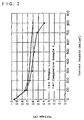
- the current-voltage characteristics of the obtained cell is shown in Fig. 2.
- a catalyst layer was formed by using a conventionally and commonly employed screen printing method with the same ink as in Example 1.
- the screen printing method it is difficult to print the ink on the surface of the polymer electrolyte membrane.
- the ink was screen printed on the same carbon paper, which had been subjected to the water repellent treatment, as in Example 1 in a conventional manner.
- a 100-mesh screen was used.
- the electrode thus obtained was sufficiently dried at 80°C to remove the solvent therefrom, and then the polymer electrolyte membrane was interposed between two electrodes. Then, the same unit cell was assembled as in Example 1 to perform the same operation.
- the current-voltage characteristics of the obtained cell is shown in Fig. 2.
- Example 3 The same procedure as in Example 1 was conducted, except that the ink was sprayed onto surfaces of two carbon papers which had been subjected to a water repellent treatment in place of the polymer electrolyte membrane to form a porous catalyst layer. Then a MEA was obtained by interposing the same polymer electrolyte membrane as Example 1 between the two carbon papers with the formed catalyst layer facing inside. The current-voltage characteristics of the obtained cell is shown together with the result of Comparative Example 1 in Fig. 3.
- Figs. 2 and 3 indicate that the unit cell including the porous catalyst layer in accordance with the present invention is more excellent in the characteristics than the unit cell using the electrode manufactured by the screen printing method.
- Fig. 4 shows a schematic cross sectional view of the porous catalyst layer formed on the carbon paper by the spray application.
- Fig. 5 shows a schematic cross sectional view of the catalyst layer formed on the carbon paper by a screen printing method.
- a numeral 13 denotes a micropore
- a numeral 14 denotes a catalyst layer
- a numeral 15 denotes a carbon paper.
- the ink containing a catalyst powder is sprayed onto the surface of the polymer electrolyte membrane or the porous conductive base material, most of the solvent in the ink is vaporized prior to adhesion of the ink onto the surface of the polymer electrolyte membrane or the porous conductive base material. Therefore, the ink is applied on, or rather adheres to the surface of the polymer electrolyte membrane or the porous conductive base material in such a manner that the catalyst powder is deposited thereon.
- the porous catalyst layer thus formed enables to produce an electrode having higher gas diffusion rate.
- the spray application since most of the solvent in the ink is vaporized, the polymer electrolyte membrane is not swelled with the solvent. Accordingly, the adhesion between the polymer electrolyte membrane and the porous catalyst layer is enhanced.
- the catalyst layer is closely formed on the carbon paper, and hence the number of the micropores 13 is decreased.
- the electrode formed by spraying the ink containing the catalyst powder dispersed therein onto the surface of the polymer electrolyte membrane or the carbon paper is more excellent in structure as well as performances as compared with the electrode manufactured by the conventional screen printing method.
- a polymer electrolyte fuel cell which comprises a pair of electrodes, a polymer electrolyte membrane interposed between the pair of the electrodes, a first conductive separator having a channel for supplying an oxidant gas to one of the electrodes therethrough, and a second conductive separator having a channel for supplying a fuel gas to the other of said electrodes therethrough, wherein at least one of the electrodes comprises a porous catalyst layer formed on the surface of the polymer electrolyte membrane, or formed on the surface of a porous conductive base material, the porous catalyst layer facing the polymer electrolyte membrane.
Landscapes
- Chemical & Material Sciences (AREA)
- Engineering & Computer Science (AREA)
- Chemical Kinetics & Catalysis (AREA)
- Electrochemistry (AREA)
- General Chemical & Material Sciences (AREA)
- Manufacturing & Machinery (AREA)
- Materials Engineering (AREA)
- Life Sciences & Earth Sciences (AREA)
- Sustainable Development (AREA)
- Sustainable Energy (AREA)
- Inert Electrodes (AREA)
- Fuel Cell (AREA)
Abstract
Description
Claims (4)
- A polymer electrolyte fuel cell comprising a pair of electrodes, a polymer electrolyte membrane interposed between said pair of electrodes, a first conductive separator having a channel for supplying an oxidant gas to one of said electrodes therethrough, and a second conductive separator having a channel for supplying a fuel gas to the other of said electrodes therethrough,
wherein at least one of said electrodes comprises a porous conductive base material and a porous catalyst layer formed on a surface of said polymer electrolyte membrane. - A polymer electrolyte fuel cell comprising a pair of electrodes, a polymer electrolyte membrane interposed between said pair of electrodes, and a first conductive separator having a channel for supplying an oxidant gas to one of said electrodes therethrough, and a second conductive separator having a channel for supplying a fuel gas to the other of said electrodes therethrough,
wherein at least one of said electrodes comprises a porous conductive base material and a porous catalyst layer formed on a surface of said porous conductive base material, said porous catalyst layer facing said polymer electrolyte membrane. - A method for manufacturing a polymer electrolyte fuel cell comprising a step of obtaining an electrode by forming a porous catalyst layer by spraying an ink containing a catalyst powder dispersed therein onto a surface of a polymer electrolyte membrane or a porous conductive base material.
- The method for manufacturing a polymer electrolyte fuel cell in accordance with claim 3,
wherein said ink contains a catalyst powder; a catalyst powder and a polymer electrolyte; or a catalyst powder, a polymer electrolyte, and a water repellent-treated carbon powder.
Applications Claiming Priority (2)
| Application Number | Priority Date | Filing Date | Title |
|---|---|---|---|
| JP24213299A JP4093439B2 (en) | 1999-08-27 | 1999-08-27 | Method for producing electrode for polymer electrolyte fuel cell |
| JP24213299 | 1999-08-27 |
Publications (2)
| Publication Number | Publication Date |
|---|---|
| EP1079451A2 true EP1079451A2 (en) | 2001-02-28 |
| EP1079451A3 EP1079451A3 (en) | 2003-08-06 |
Family
ID=17084792
Family Applications (1)
| Application Number | Title | Priority Date | Filing Date |
|---|---|---|---|
| EP00118582A Withdrawn EP1079451A3 (en) | 1999-08-27 | 2000-08-25 | Polymer electrolyte fuel cell and method for manufacturing the same |
Country Status (4)
| Country | Link |
|---|---|
| US (1) | US6667268B1 (en) |
| EP (1) | EP1079451A3 (en) |
| JP (1) | JP4093439B2 (en) |
| CN (1) | CN1134081C (en) |
Cited By (2)
| Publication number | Priority date | Publication date | Assignee | Title |
|---|---|---|---|---|
| EP1503439A2 (en) | 2003-07-30 | 2005-02-02 | JSR Corporation | Process of producing electrode paste and electrode paste composition |
| WO2008094374A3 (en) * | 2007-01-31 | 2008-10-09 | Motorola Inc | Micro fuel cell having macroporous metal current collectors |
Families Citing this family (18)
| Publication number | Priority date | Publication date | Assignee | Title |
|---|---|---|---|---|
| JP2003109612A (en) * | 2001-09-27 | 2003-04-11 | Asahi Glass Co Ltd | Method for producing gas diffusion electrode for polymer electrolyte fuel cell |
| KR100435323B1 (en) * | 2001-12-11 | 2004-06-10 | 현대자동차주식회사 | Direct coating type auto spraying system and fabrication of the high performance membrane-electrode assembly |
| GB0200253D0 (en) * | 2002-01-08 | 2002-02-20 | Johnson Matthey Plc | Improved material for electrode manufacture |
| US6893119B2 (en) * | 2002-08-02 | 2005-05-17 | Fuji Photo Film Co., Ltd. | Expendables unit, equipment, and printer |
| US20050272595A1 (en) * | 2002-10-16 | 2005-12-08 | Canon Kabushi Kaisha | Manufacturing process for fuel cell, and fuel cell apparatus |
| JP2004241362A (en) * | 2002-12-09 | 2004-08-26 | Toyota Motor Corp | Membrane electrode assembly and method for producing the same |
| JP3945440B2 (en) * | 2003-03-31 | 2007-07-18 | セイコーエプソン株式会社 | FUEL CELL, ITS MANUFACTURING METHOD, ELECTRONIC DEVICE, AND AUTOMOBILE |
| TWI274084B (en) | 2003-08-05 | 2007-02-21 | Lg Chemical Ltd | Hybrid membrane-electrode assembly with minimal interfacial resistance and preparation method thereof |
| JP4737924B2 (en) * | 2003-08-11 | 2011-08-03 | ノードソン コーポレーション | ELECTROLYTE MEMBRANE FOR FUEL CELL, ELECTROLYTE MEMBRANE COMPOSITION, METHOD FOR PRODUCING ROLL STOCK OF ELECTROLYTE MEMBRANE COMPOSITION, METHOD FOR PRODUCING ELECTROLYTE MEMBRANE / electrode assembly FOR FUEL CELL, AND METHOD FOR PRODUCING FUEL CELL |
| JP3912384B2 (en) * | 2004-02-10 | 2007-05-09 | セイコーエプソン株式会社 | Manufacturing method of fuel cell |
| ATE553510T1 (en) | 2004-05-13 | 2012-04-15 | Lg Chemical Ltd | SYSTEM AND METHOD FOR FORMING A MEMBRANE ELECTRODE ASSEMBLY FOR FUEL CELLS |
| EP1829147A2 (en) | 2004-11-16 | 2007-09-05 | Battelle Memorial Institute | Solution based enhancements of fuel cell components and other electrochemical systems and devices |
| KR101201816B1 (en) | 2005-03-07 | 2012-11-15 | 삼성에스디아이 주식회사 | Membrane-electrode assembly, method for preparing the same, and fuel cell system comprising the same |
| KR100760219B1 (en) | 2005-08-01 | 2007-10-05 | 연세대학교 산학협력단 | Method for manufacturing electrochemical cell by robo dispensing, its urea material paste, and solid oxide fuel cell produced thereby |
| US20100285388A1 (en) * | 2007-05-18 | 2010-11-11 | Sim Composites Inc. | Catalyst-coated proton exchange membrane and process of producing same |
| JP2011150978A (en) * | 2010-01-25 | 2011-08-04 | Toyota Motor Corp | Electrode manufacturing device and electrode manufacturing method |
| KR20210116751A (en) * | 2020-03-13 | 2021-09-28 | 이오플로우(주) | Electroosmotic pump, method for preparing thereof, and system for pumping of fluid comprising thereof |
| CN111900422A (en) * | 2020-07-07 | 2020-11-06 | 浙江锋源氢能科技有限公司 | Catalyst layer of fuel cell and preparation method thereof |
Family Cites Families (8)
| Publication number | Priority date | Publication date | Assignee | Title |
|---|---|---|---|---|
| JPS5620178A (en) * | 1979-07-30 | 1981-02-25 | Asahi Glass Co Ltd | Closely sticking method for ion exchange membrane and electrode |
| JP3422377B2 (en) | 1993-08-06 | 2003-06-30 | 松下電器産業株式会社 | Method for manufacturing polymer electrolyte fuel cell and polymer electrolyte fuel cell obtained by the method |
| US5547911A (en) | 1994-10-11 | 1996-08-20 | E. I. Du Pont De Nemours And Company | Process of imprinting catalytically active particles on membrane |
| US5843519A (en) * | 1994-10-17 | 1998-12-01 | Tanaka Kikinzoku Kogyo K.K. | Process for forming a catalyst layer on an electrode by spray-drying |
| DE19544323A1 (en) * | 1995-11-28 | 1997-06-05 | Magnet Motor Gmbh | Gas diffusion electrode for polymer electrolyte membrane fuel cells |
| US5672439A (en) | 1995-12-18 | 1997-09-30 | Ballard Power Systems, Inc. | Method and apparatus for reducing reactant crossover in an electrochemical fuel cell |
| US6221523B1 (en) * | 1998-02-10 | 2001-04-24 | California Institute Of Technology | Direct deposit of catalyst on the membrane of direct feed fuel cells |
| DE19812592B4 (en) * | 1998-03-23 | 2004-05-13 | Umicore Ag & Co.Kg | Membrane electrode unit for polymer electrolyte fuel cells, process for their production and ink |
-
1999
- 1999-08-27 JP JP24213299A patent/JP4093439B2/en not_active Expired - Fee Related
-
2000
- 2000-08-18 CN CNB001262408A patent/CN1134081C/en not_active Expired - Fee Related
- 2000-08-25 US US09/648,117 patent/US6667268B1/en not_active Expired - Fee Related
- 2000-08-25 EP EP00118582A patent/EP1079451A3/en not_active Withdrawn
Cited By (3)
| Publication number | Priority date | Publication date | Assignee | Title |
|---|---|---|---|---|
| EP1503439A2 (en) | 2003-07-30 | 2005-02-02 | JSR Corporation | Process of producing electrode paste and electrode paste composition |
| EP1503439A3 (en) * | 2003-07-30 | 2007-09-26 | JSR Corporation | Process of producing electrode paste and electrode paste composition |
| WO2008094374A3 (en) * | 2007-01-31 | 2008-10-09 | Motorola Inc | Micro fuel cell having macroporous metal current collectors |
Also Published As
| Publication number | Publication date |
|---|---|
| EP1079451A3 (en) | 2003-08-06 |
| JP4093439B2 (en) | 2008-06-04 |
| CN1134081C (en) | 2004-01-07 |
| JP2001068119A (en) | 2001-03-16 |
| CN1286505A (en) | 2001-03-07 |
| US6667268B1 (en) | 2003-12-23 |
Similar Documents
| Publication | Publication Date | Title |
|---|---|---|
| US6667268B1 (en) | Polymer electrolyte fuel cell having a porous catalyst layer and a method for manufacturing the same | |
| US6627035B2 (en) | Gas diffusion electrode manufacture and MEA fabrication | |
| KR100437293B1 (en) | Polymer electrolytic fuel cell and method for producing the same | |
| EP0948071A2 (en) | Electrode for fuel cell and method of producing the same | |
| EP1304753B1 (en) | Polyelectrolyte fuel cell | |
| KR100448168B1 (en) | A preparing method of Membrane-Electrode-Gasket Assembly for fuel cell | |
| EP1318559B9 (en) | Method for the production of membrane electrode assemblies for fuel cells | |
| CA2436261C (en) | Process for the manufacture of catalyst-coated substrates | |
| EP2124275A1 (en) | Apparatus for manufacturing electrode for polymer electrolyte fuel cell, and method of manufacturing the same | |
| EP1387423A1 (en) | Water-based catalyst inks and their use for manufacture of catalyst-coated substrates | |
| JPWO2001022514A1 (en) | Polymer electrolyte fuel cell and method of manufacturing the same | |
| US20030232714A1 (en) | Method of making membrane electrode assemblies | |
| CN1623243A (en) | Method for preparing membrane electrode assembly | |
| US20050163920A1 (en) | Membrane electrode assembly prepared by direct spray of catalyst to membrane | |
| EP1378952A1 (en) | Treated gas diffusion backings and their use in fuel cells | |
| CA2640961A1 (en) | Method of making membrane electrode assemblies | |
| EP1734602A1 (en) | Powder catalyst material, method for producing same and electrode for solid polymer fuel cell using same | |
| US7005397B2 (en) | Electrode for polymer electrolyte fuel cell and method of producing the same | |
| US20040175506A1 (en) | Application of an ionomer layer to a substrate and products related thereto | |
| US6579639B1 (en) | Polymer electrolyte fuel cell | |
| WO2004036678A1 (en) | Manufacturing process for fuel cell, and fuel cell apparatus | |
| EP1984967B1 (en) | Method of forming membrane electrode assemblies for electrochemical devices | |
| KR100689105B1 (en) | Method for producing catalyst layer of fuel cell using capillary process | |
| CN101288191B (en) | Method for preparing catalyst coated membrane using mask | |
| JP2026064398A (en) | Gas diffusion layer for fuel cells |
Legal Events
| Date | Code | Title | Description |
|---|---|---|---|
| PUAI | Public reference made under article 153(3) epc to a published international application that has entered the european phase |
Free format text: ORIGINAL CODE: 0009012 |
|
| AK | Designated contracting states |
Kind code of ref document: A2 Designated state(s): AT BE CH CY DE DK ES FI FR GB GR IE IT LI LU MC NL PT SE |
|
| AX | Request for extension of the european patent |
Free format text: AL;LT;LV;MK;RO;SI |
|
| PUAL | Search report despatched |
Free format text: ORIGINAL CODE: 0009013 |
|
| AK | Designated contracting states |
Designated state(s): AT BE CH CY DE DK ES FI FR GB GR IE IT LI LU MC NL PT SE |
|
| AX | Request for extension of the european patent |
Extension state: AL LT LV MK RO SI |
|
| RIC1 | Information provided on ipc code assigned before grant |
Ipc: 7H 01M 4/88 B Ipc: 7H 01M 8/10 B Ipc: 7H 01M 4/86 A |
|
| 17P | Request for examination filed |
Effective date: 20040109 |
|
| AKX | Designation fees paid |
Designated state(s): DE FR GB |
|
| RAP1 | Party data changed (applicant data changed or rights of an application transferred) |
Owner name: PANASONIC CORPORATION |
|
| STAA | Information on the status of an ep patent application or granted ep patent |
Free format text: STATUS: THE APPLICATION IS DEEMED TO BE WITHDRAWN |
|
| 18D | Application deemed to be withdrawn |
Effective date: 20091014 |