EP1079386A2 - Cassette storage case - Google Patents
Cassette storage case Download PDFInfo
- Publication number
- EP1079386A2 EP1079386A2 EP00402302A EP00402302A EP1079386A2 EP 1079386 A2 EP1079386 A2 EP 1079386A2 EP 00402302 A EP00402302 A EP 00402302A EP 00402302 A EP00402302 A EP 00402302A EP 1079386 A2 EP1079386 A2 EP 1079386A2
- Authority
- EP
- European Patent Office
- Prior art keywords
- cassette
- storage case
- lower half
- cassette storage
- upper half
- Prior art date
- Legal status (The legal status is an assumption and is not a legal conclusion. Google has not performed a legal analysis and makes no representation as to the accuracy of the status listed.)
- Withdrawn
Links
Images






Classifications
-
- G—PHYSICS
- G11—INFORMATION STORAGE
- G11B—INFORMATION STORAGE BASED ON RELATIVE MOVEMENT BETWEEN RECORD CARRIER AND TRANSDUCER
- G11B23/00—Record carriers not specific to the method of recording or reproducing; Accessories, e.g. containers, specially adapted for co-operation with the recording or reproducing apparatus ; Intermediate mediums; Apparatus or processes specially adapted for their manufacture
- G11B23/02—Containers; Storing means both adapted to cooperate with the recording or reproducing means
- G11B23/03—Containers for flat record carriers
-
- G—PHYSICS
- G11—INFORMATION STORAGE
- G11B—INFORMATION STORAGE BASED ON RELATIVE MOVEMENT BETWEEN RECORD CARRIER AND TRANSDUCER
- G11B23/00—Record carriers not specific to the method of recording or reproducing; Accessories, e.g. containers, specially adapted for co-operation with the recording or reproducing apparatus ; Intermediate mediums; Apparatus or processes specially adapted for their manufacture
- G11B23/02—Containers; Storing means both adapted to cooperate with the recording or reproducing means
- G11B23/023—Containers for magazines or cassettes
- G11B23/0233—Containers for a single cassette
Definitions
- the present invention relates to a cassette storage case preferable for storage of a tape cassette such as audio compact cassette and more particularly to a slide type cassette storage case in which a cassette is inserted laterally from an insertion port provided on a side of the case and stored.
- a compact cassette for use in audio equipment or the like is stored in a cassette storage case made of plastic or the like when it is not used.
- This cassette storage case is a slide type cassette storage case in which a cassette is inserted laterally through an insertion port provided on a side surface of the case and stored.
- reference numeral 11 denotes a cassette storage case and an audio compact cassette I (hereinafter referred to as cassette) is inserted laterally into this cassette storage case 11 through an insertion port 14 provided on a side surface thereof and stored therein.
- cassette an audio compact cassette I
- a case 2 of this cassette 1 has a thin casing structure in which a reel driving shaft insertion hole 3 is formed on each of the right and left sides. Inside the cassette case 2, a pair of tape reels 5 is rotatably accommodated in a magnetic tape 4 corresponding to the reel driving shaft insertion holes 3.
- An opening 6 in which the magnetic tape 4 is exposed is formed on a front surface of the cassette case 2.
- a tape running path is formed such that the magnetic tape 4 from one side of the tape reel 5 (supply side reel) is wound up by the other side of the tape reel 5 (windup side reel) through this opening portion 6.
- a magnetic head and the like are inserted into this opening portion 6 from a cassette deck.
- trapezoidal expanded portions 7 which are expanded from both sides of up and down are formed on a front portion of the cassette case 2.
- capstan shaft insertion holes 8 and positioning reference holes 9 are formed symmetrically on the right and left sides of this expanded portion 7.
- the cassette storage case 11 in which this cassette 1 is to be inserted is comprised of a upper half 12 and a lower half 13, which are joined together.
- the upper half 12 is plastic molding product molded of, for example, GPPS (general purpose polystyrene) and the lower half 13 is plastic molding product molded of, for example, HIPS (impact resistant polystyrene). With the upper half 12 and the lower half 13 joined together, they are integrated with each other by ultrasonic fusion.
- a completely open insertion port 14 is provided on a side surface of this cassette storage case 11.
- the cassette 1 is inserted laterally (in the longitudinal direction of the cassette case 2) through this insertion port 14 and stored therein.
- This cassette storage case 11 is so constructed as to incorporate the cassette 1 substantially without any gap.
- concave grooves 15, 16 which recess from expanded portions 7 of the cassette 1 are formed on inner surface sides of the upper half 12 and lower half 13 in the lateral direction or in a cassette insertion direction.
- an opening portion 17 of an elongated hole long in the cassette insertion direction is formed in the central portion of the upper half 12 of the cassette storage case 11.
- stopper pieces 18 are provided inside this cassette storage case 11, stopper pieces 18 are provided to prevent the cassette 1 from jumping out of such a cassette storage state.
- a stopper piece 18 is formed integrally with the lower half 13 so as to protrude and an engaging protrusion 18a is provided at a tip portion thereof.
- the engaging protrusion 18a of this stopper piece 18 engages with an error erase preventing detection hole (not shown) provided in the back of the cassette case 2.
- the cassette 1 is held in a lightly locked state in the cassette storage case 11, thereby preventing the cassette 1 from jumping out (slipping out) of the cassette storage case I unexpectedly.
- reel stopper pieces 19b are provided inside the cassette storage case 11 to prevent an unnecessary rotation of the tape reels 5 in the cassette 1, thereby preventing its magnetic tape from being loose.
- a reel stopper member 19 is a plastic molding product molded of for example, polypropylene (PP), in which reel stopper pieces 19b corresponding to reel driving shaft insertion holes 3 of the cassette 1 are formed on a base plate portion 19a thereof so as to be erected. Then, the base plate portion 19a is crimped to crimping protrusions 20 provided substantially in the center of the inner surface of the lower half 13 so as to protrude.
- PP polypropylene
- the reel stopper pieces 19b are subjected to elastic deformation so that they are pressed down by the cassette 1.
- the reel driving shaft insertion holes 3 of the cassette 1 correspond to the reel stopper pieces 19b, so that the reel stopper pieces 19b are elastically restored to their erected state.
- the reel stopper pieces 19b engage with the engaging protrusions 5a on an inner circumference of the tape reel 5, thereby blocking a rotation of the tape reel 5.
- the conventional cassette storage case 11 is comprised of three parts including the upper half 12, the lower half 13 and the reel stopper member 19.
- the reel stopper member 19 is cnmped to the lower half 13 and after that, the upper half 12 and the lower half 13 are fused together by ultrasonic wave.
- the cassette storage case 11 has to be formed in such a size large enough for accommodating the cassette 1 completely.
- the length thereof in the cassette insertion direction needs to be increased by a length of the protrusion 10.
- the size of the cassette storage case increases and more molding material is employed thereby leading to an increase of production cost.
- the problem becomes large in the case where the deep wall portion is to be formed by superposing the upper half on the lower half as is particularly shown in FIG. 11.
- this cassette storage case is formed of resin material such as polypropylene as described above, there is such a problem that due to the characteristic of resin, warp or surface sink (deformation in a concave state) is generated due to contraction after molding (particularly polypropylene is contracted largely after molding because of crystalline resin so that an excessive warp or surface sink may be generated).
- Such a warp or surface sink is likely to be generated in a portion having a large difference of thickness in a completed product. That is, because in the conventional cassette storage case described above, there is a large difference of thickness between the concave groove which retreats from the expanded portion of the cassette and the thick portion along the concave groove, the warp or surface sink is often generated at this portion after molding, so that the quality of a completed case is largely impaired.
- the present invention is implemented in view of such problems and its object is, in the slide type cassette storage case in which a cassette is laterally inserted from an inserting port provided on one side surface thereof, to offer a new cassette storage case capable of ensuring a state in which the cassette is stored and in concrete terms.
- the present invention provides
- the upper half and the lower half are fixed to each other by engagement.
- polypropyle resin is used as molding material thereof.
- the cassette storage case of the present invention having such a structure can be assembled easily without generating a deviation or a difference of step between the upper half and the lower half at the time of assembly, thereby improving production efficiency and making it possible to reduce production cost.
- the first embodiment comprises mainly a configuration related to 1) of means for solving the problems and includes a configuration related to 4) of means for solving the problems.
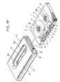
- reference numeral 31 denotes a cassette storage case of the present invention.
- This cassette storage case 31 is comprised of a upper half (cover halo 32 and a lower half(base half 33 and is so constructed that a cassette 1 is inserted by sliding laterally through an insertion port 34 provided on a side surface thereof and stored.
- Polypropylene resin is preferably used as molding material of this cassette storage case 31.
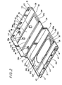
- the cassette storage case is molded integrally in a developed state in which the upper half 32 and the lower half 33 are linked to each other as shown in FIG. 2.
- a side wall portion 32b of the upper half 32 and a side edge portion 33b of the lower half 33 are linked to each other through a thin link portion 40.
- the upper half 32 is bent with respect to the lower half 33 with this link portion 40 as a hinge and joined thereto.
- the upper half 32 and the lower half 33 are joined together such that a side wall portion 32c and a deep wall portion 32d of the upper half 32 overlap inner surfaces of a side wall portion 33c and a deep wall portion 33d of the lower half 33 and then, with this joining state, they are fixed to each other by engagement.
- fitting convex portions 41 are provided at multiple positions of an outer surface of the side wall portion 32c of the upper half 32 and an engaging hole 42 is formed at each of them.
- notched fitting concave portions 43 are formed in the side wall portion 33c of the lower half 33 correspondingly and an engaging protrusion 44 is provided so as to protrude there.
- This engaging protrusion 44 is formed in a tapered hook shape such that a tip thereof has a width.
- FIG. 3 shows its essential portion.
- the fitting convex portion 41 is fit in the fitting concave 43 while the upper half 32 and the lower half 33 are in a state of being joined and at the same time, the engaging protrusion 43 engages with the engaging hole 42 by being press-fit thereinto. Consequently there is provided a structure in which the upper half 32 and the lower half 34 are correctly, surely and solidly joined.
- the upper half 32 and the lower half 33 each have an open surface 32a, 33a which has no side wall.
- the open surfaces 32a, 33a are joined together so as to form an insertion port 34.
- the cassette 1 is inserted by sliding laterally through this insertion port 34.
- This cassette storage case 31 is so constructed as to incorporate the cassette 1 substantially without any gap.
- concave grooves 35, 36 which recess from expanded portions 7 of the cassette 1 are formed on the inner surface side of each of the upper half 32 and lower half 33 in a cassette insertion direction.
- the concave grooves 35, 36 are provided symmetrically on both sides in the cassette insertion direction, so that the cassette 1 can be inserted into the cassette storage case 31 irrespective of setting the expanded portion 7 on the left side in the cassette insertion direction or on the right side.
- a central portion (portion between the concave grooves 35 on both sides) on the inner surface side of the upper half 32 is formed of a thin portion 32g excluding thick portions 32e, 32f along the concave portions 35 and open surface 32a.
- the central portion (portion between the concave grooves 36 on both sides) on the inner surface side of the lower half 33 is formed of a thin portion 33g excluding thick portions 33e, 33f along the concave portions 36 and open surface 33a.
- an opening portion 37 of an elongated hole long in the cassette insertion direction is formed in the central portion of the upper half 32 of the cassette storage case 31.
- a rib 37a is formed around the opening portion 37 in the thin portion 32g on the inner surface side of the upper half 32 so as to improve the strength of the upper half 32 thereby preventing a distortion.
- stopper pieces 38 are provided inside this cassette storage case 31 to prevent the cassette 1 from jumping out of such cassette 1 storage condition.
- This stopper piece 38 is formed by providing the lower half 33 of the cassette storage case 31 within the concave groove 36 thereof with a U-shape notched groove and an engaging protrusion 38a is provided at a front end thereof.
- the stopper pieces 38 are pressed down by the expanded portions 7 of the cassette 1 for a while.
- the engaging protrusion 38a engages with a capstan shaft insertion hole 8 in the expanded portion 7 of the cassette 1 by its elastic repellent force. Consequently, the cassette 1 is held in light locking state within the cassette storage case 31, thereby preventing the cassette 1 from jumping out (slipping out) of the cassette storage case 31 unexpectedly.
- this cassette storage case 31 is so constructed that the cassette 1 can be inserted thereinto in any direction of the cassette as described above, correspondingly, the stopper pieces 38 are provided symmetrically on both the right and left sides in the cassette insertion direction.
- reel stopper pieces 39 are provided inside the cassette storage case 31 to prevent an unnecessary rotation of the tape reels 5 in the cassette 1 thereby preventing its magnetic tape from being loose.
- This reel stopper piece 39 is formed integrally on the thin portion 33g so as to rise up on the inner surface side of the lower half 33 corresponding to the reel driving shaft insertion holes 3 of the cassette 1.
- two pieces provided in parallel in the cassette insertion direction act as a pair.
- the reel stoppers 39 are subjected to elastic deformation with the result that they are pressed down by the cassette 1.
- the reel driving shaft insertion holes 3 of the cassette 1 correspond to the reel stopper pieces 39, so that the reel stopper pieces 39 are elastically restored to their erected state.
- the reel stopper pieces 39 engage with the engaging protrusions 5a on an inner circumference of the tape reel 5, thereby blocking a rotation of the tape reel 5.
- Two pieces of the reel stopper pieces 39 engage with the tape reels 5 at the same time, so that a rotation of the tape reels 5 can be blocked securely.
- a concave notch 45 which retreats from the protrusion 10 on the side surface portion 2a of the cassette 1 is formed on a deep wall portion 32d of the upper half 32 opposing the side surface portion 2a when the cassette 1 is stored.
- this cassette storage case 31 is so constructed that the cassette 1 can be inserted in any direction as described above, correspondingly, the notches 45 are formed symmetrically on both the right and left in the cassette insertion direction.
- the thickness "a" of the deep wall portion 32d in which the notch 45 is to be formed is preferred to be the same as or larger than a protruding length "b" of the protrusion 10 of the cassette 1.
- the notch 45 Because the thickness "a" of the deep wall portion 32d in which the notch 45 is to be formed as described above is the same as or larger than the protruding length "b" of the protrusion 10 of the cassette 1, the notch 45 has a plenty of room for accommodating the protrusion 10 of the cassette 1. Consequently, the cassette 1 is stored in a stabilized state.
- the length in the cassette insertion direction of the cassette storage case 31 can be reduced by a length corresponding to the protrusion 10 as compared to the conventional one.
- the size of the case can be reduced and an amount of molding material for use can be suppressed, thereby leading to reduction of production cost.
- the second such embodiment comprises a configuration related to 2), 3) of means for solving the problems and includes a configuration related to 4) of means for solving the problems.
- reference numeral 31 denotes a cassette storage case and this cassette storage case 31 is comprised of a pair of cassette halves, namely, upper half (cover half) 32 and a lower half (base half) 33. Then, a cassette 1 is inserted laterally through an insertion port 34 provided on a side surface and stored there.
- Polypropylene resin is preferably used as molding material of this cassette storage case 31.
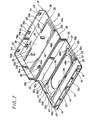
- the cassette storage case is molded integrally in a developed state in which the upper half 32 and the lower half 33 are linked to each other as shown in FIG. 7.
- the prominent structure of the present invention in the cassette storage case 31 having such a structure is that the thickness missing portion 45, as is shown in FIG. 7, is provided substantially in the center of the thick portion 33e along the concave groove 36 of the lower half 33.
- the thick portion 33e is formed over the entire length of the cassette in the cassette insertion direction along the concave groove 36, according to this embodiment, front and rear portions in the cassette insertion direction along each of the concave grooves 36 are left as the thick portions 33e so as to form a central portion therebetween as the thickness missing portion 45.
- the thickness missing portion 45 is formed such that the thickness of the case at this thickness missing portion 45 is the same as that of the thin portion 33g (that is, the thickness of the thick portion is eliminated so that it becomes the same plane as the thin portion 33g).
- a difference of thickness between the concave groove 36 of the lower half 33 and the thick portion 33e along the concave groove 36 can be reduced so that a change of the thickness between the concave groove 36 and the thick portion 33e becomes gentle.
- a generation of warp or surface sink at this portion is effectively prevented.
- both end portions 45a (a portion between the thickness missing portion 45 and the thick portion 33e) of each of the thickness missing portions 45 provided in the center of the thick portion 33e is formed in a gentle slope.
- the cassette 1 when the cassette 1 is taken in or out, it is not caught by the end portions 45a of the thickness missing portion 45 or if a label is pasted on the cassette, the label is not caught by the end portions 45a of the thickness missing portion 45.
- the cassette can be taken in or out smoothly.
- cassette holding portions 47 are provided so as to hold the cassette 1 substantially without any gap.
- the cassette holding portions 47 are formed so as to be swollen at front and rear end portions in the cassette insertion direction of the thick portion 32e along each of the concave grooves 35.
- the cassette holding portions at both ends thereof are formed thicker and a central portion therebetween is formed as the thickness missing portion 48 thinner than the cassette holding portion 47.
- a height "a" of the cassette holding portion 47 is formed substantially the same as a gap "b" between the cassette 1 and the upper half 32 when the cassette 1 is stored in a state that it is located near the lower half 33.
- the cassette 1 is stored and held by the cassette holding portion 47 such that there is substantially no gap in the case.
- the thickness missing portion 48 is provided in the central portion between the cassette holding portions 47 at both ends, a generation of warp or surface sink at this portion is effectively prevented after molding of the case.
- both end portions 48a portion between the thickness missing portion 48 and the cassette holding portion 47 of each of the thickness missing portions 48 is formed in a gentle slope.
- cassette half lower half 33 in this example
- cassette half upper half 32 in this example
- the reel stopper pieces 39 of the lower half 33 are deformed such that they are pressed down. Because in this structure, the thickness missing portions 48 are provided on the upper half 32 which is an opposite side of the reel stopper pieces 39, the cassette 1 is capable of moving away toward the upper half 32 in the case except near the insertion port. Therefore, the reel stopper pieces 39 are deformed without any limitation and restored to engage with the tape reel 5.
- the cassette 1 reaches the deepest portion of the case, the cassette 1 is held such that it rides over the cassette holding portion 47. As a result, the cassette can be taken in and out easily and when it is carried, looseness of the cassette is prevented securely.
- the cassette storage case 31 is molded integrally such that the upper half 32 and the lower half 33 are linked to each other. By bending with respect to the link portion 40, they are assembled by engagement. As a result, the assembly can be carried out easily without generating a deviation or a difference of step between the upper half 32 and the lower half 33.
- reel stopper pieces 39 for blocking a rotation of the tape reels 5 in the cassette 5 are formed integrally with the cassette storage case 31, a process for installing the reel stopper pieces 39 is not necessary unlike conventionally. Thus, the assembly is further facilitated.
- This cassette storage case 31 is molded of polypropylene. Because this is material having an excellent impact resistance and heat resistance, it is possible to provide a high quality cassette storage case by taking advantage of the characteristic of that material.
- polypropylene resin is material lighter than polystyrene resin conventionally used, it contributes to reduction of the weight of the cassette storage case.
- the present invention may be applied to such a cassette storage case in which the upper half and the lower half are molded separately and assembled by ultrasonic wave fusion or the like.
- the notch which retreats from a protrusion on a side surface portion of a tape cassette is formed in the deep wall portion thereof.
- the thickness missing portions are provided substantially in the center of the thick portion along the concave groove which retreats from the expanded portion of a tape cassette.
- the difference of the thickness between the concave groove and the thick portion can be reduced. Therefore, a generation of the warp or surface sink at this portion after molding of the case is effectively suppressed so that a high quality cassette storage case can be provided.
- the cassette storage case can be assembled easily without generating a deviation or difference of step between the upper half and the lower half, production efficiency is improved thereby leading to reduction of production cost and at the same time, because polypropylen resin is used as the molding material of the cassette storage case, impact resistance and heat resistance thereof can be improved and further, the reduction of the weight thereof can be achieved.
Landscapes
- Packaging Of Annular Or Rod-Shaped Articles, Wearing Apparel, Cassettes, Or The Like (AREA)
Abstract
Description
Claims (10)
- A cassette storage case comprised of a upper half (32) and a lower half (33) and in which a tape cassette (1) is inserted laterally through an insertion port (34) provided on a side surface thereof and stored, whereinthe cassette storage case (31) is molded integrally such that the upper half (32) and the lower half (33) are linked to each other in a developed state thereof and by bending a link portion between the upper half (32) and the lower half (33) as a hinge at the time of assembly, the upper half (32) and the lower half (33) are joined to each other andreel stopper pieces (39) elastically deformable so as to engage with tape reels (5) in the tape cassette to block a rotation thereof are formed integrally with an inner surface of the lower half (33).
- A cassette storage case according to claim 1, wherein polypropylene resin is used as molding material thereof.
- A cassette storage case comprised of a upper half (32) and a lower half (33) and in which a tape cassette (1) is inserted laterally through an insertion port (34) provided on a side surface thereof and stored, wherein
a deep wall portion opposing said inserting port (34) is formed such that a deep wall (32d) of the upper half (32) is superposed on a deep wall (33d) of the lower half (33) and a notch (45) which retreats from a protrusion (10) provided on a side surface portion (2a) of the cassette (1) is formed on the inner surface side of the deep wall portion (32d). - The cassette storage case according to claim 3, wherein a thickness (a) of the deep wall portion (32d) in which the notch (45) is formed is larger than a protruding length (b) of the protrusion (10) of the tape cassette (1).
- A cassette storage case having a structure in which a tape cassette (1) is inserted laterally through an insertion port (34) provided on a side surface thereof and stored and having concave grooves (35, 36) which retreat from an expanded portion of the tape cassette (1) formed in a cassette insertion direction of an inner surface of the case, wherein
thickness missing portions (48, 45) are provided substantially in the center of the thick portion (32e, 33e) along the concave grooves. - The cassette storage case according to claim 5, wherein front and rear portions (47) in the cassette insertion direction along the concave grooves (35, 36) are formed thick while the other portions thereof are formed as thickness missing portions (48).
- The cassette storage case according to claim 6, wherein the front and rear end portions (47) in the cassette insertion direction along the concave grooves (35, 36) are formed as cassette holding portions for holding the tape cassette (1) substantially without any gap in the case.
- The cassette storage case according to claim 5, wherein the thickness of the thickness missing portion (45) is substantially the same as the thickness of thin portion (33g) adjacent to the thick portion (33e).
- The cassette storage case according to claim 3 or claim 5, wherein the cassette storage case (31) is constituted such that the upper half (32) and the lower half (33) are integrally molded so as to be linked to each other in a developed state thereof and by bending a link portion (40) between the upper half (32) and the lower half (33) as a hinge at the time of assembly, the upper half (32) and the lower half (33) are joined to each other and the upper half (32) and the lower half (33) are fixed by engagement.
- The cassette storage case according to claim 1 or claim 9, wherein the upper half (32) and the lower half (33) are fixed by engagement.
Applications Claiming Priority (8)
| Application Number | Priority Date | Filing Date | Title |
|---|---|---|---|
| JP11230723A JP2001055289A (en) | 1999-08-17 | 1999-08-17 | Cassette storage case |
| JP23072399 | 1999-08-17 | ||
| JP28445099 | 1999-10-05 | ||
| JP28445399 | 1999-10-05 | ||
| JP28445399A JP2001106285A (en) | 1999-10-05 | 1999-10-05 | Cassette storage case |
| JP28445099 | 1999-10-05 | ||
| JP2000155006 | 2000-05-25 | ||
| JP2000155006A JP2001171779A (en) | 1999-10-05 | 2000-05-25 | Cassette storage case |
Publications (2)
| Publication Number | Publication Date |
|---|---|
| EP1079386A2 true EP1079386A2 (en) | 2001-02-28 |
| EP1079386A3 EP1079386A3 (en) | 2001-04-11 |
Family
ID=27477420
Family Applications (1)
| Application Number | Title | Priority Date | Filing Date |
|---|---|---|---|
| EP00402302A Withdrawn EP1079386A3 (en) | 1999-08-17 | 2000-08-17 | Cassette storage case |
Country Status (5)
| Country | Link |
|---|---|
| US (2) | US6454093B1 (en) |
| EP (1) | EP1079386A3 (en) |
| KR (1) | KR20010050097A (en) |
| CN (1) | CN1284723A (en) |
| TW (1) | TW476062B (en) |
Families Citing this family (6)
| Publication number | Priority date | Publication date | Assignee | Title |
|---|---|---|---|---|
| TW476062B (en) * | 1999-08-17 | 2002-02-11 | Sony Corp | Cassette storage case |
| US20030192792A1 (en) * | 2002-04-12 | 2003-10-16 | Kensuke Tokorotani | Tape-and-disc display container for use in video rental shops |
| US8223488B2 (en) | 2004-05-10 | 2012-07-17 | Think Products, Inc. | Locking assembly for electronic tablet and other devices |
| US8456836B2 (en) | 2004-05-10 | 2013-06-04 | Think Products, Inc. | Spring loaded security slot attachment for portable device security |
| US8139356B2 (en) | 2004-05-10 | 2012-03-20 | Peter Allen | Plunger security lock and personal electronic device configured to be secured by the plunger lock |
| USD565839S1 (en) * | 2006-10-10 | 2008-04-08 | Peter Allen | Locking cage for a portable music player |
Family Cites Families (13)
| Publication number | Priority date | Publication date | Assignee | Title |
|---|---|---|---|---|
| JPS609182Y2 (en) * | 1981-06-18 | 1985-04-02 | アルファレコ−ド株式会社 | cassette tape case magazine |
| US4921097A (en) | 1989-08-01 | 1990-05-01 | Specialty Store Services, Inc. | Display case for a jacketed cassette |
| US5038932A (en) | 1990-01-30 | 1991-08-13 | Shwan Sheu | Cassette and video tape holder |
| US5085322A (en) | 1990-08-24 | 1992-02-04 | Autronic Plastics, Inc. | Bottom-load video cassette container |
| US5160028A (en) * | 1991-01-10 | 1992-11-03 | Fuji Photo Film Co., Ltd. | Magnetic tape cassette accommodating case |
| US5560481A (en) * | 1991-05-16 | 1996-10-01 | U.S. Philips Corporation | Holder for a rectangular cassette |
| JP2571079Y2 (en) | 1992-10-16 | 1998-05-13 | 富士写真フイルム株式会社 | Storage case for magnetic tape cassette |
| WO1998001369A1 (en) * | 1996-07-08 | 1998-01-15 | Sony Corporation | Cassette storage casing |
| JPH10139087A (en) * | 1996-09-11 | 1998-05-26 | Sony Corp | Cassette storage case |
| JPH10291579A (en) | 1997-04-18 | 1998-11-04 | Sony Corp | Cassette storage case |
| JP2000025873A (en) * | 1998-07-09 | 2000-01-25 | Sony Corp | Cassette storage case |
| JP2000025874A (en) | 1998-07-09 | 2000-01-25 | Sony Corp | Cassette storage case |
| TW476062B (en) * | 1999-08-17 | 2002-02-11 | Sony Corp | Cassette storage case |
-
2000
- 2000-08-14 TW TW089116352A patent/TW476062B/en not_active IP Right Cessation
- 2000-08-16 US US09/639,170 patent/US6454093B1/en not_active Expired - Fee Related
- 2000-08-17 KR KR1020000047382A patent/KR20010050097A/en not_active Withdrawn
- 2000-08-17 EP EP00402302A patent/EP1079386A3/en not_active Withdrawn
- 2000-08-17 CN CN00128662A patent/CN1284723A/en active Pending
-
2002
- 2002-09-23 US US10/251,760 patent/US20030085143A1/en not_active Abandoned
Also Published As
| Publication number | Publication date |
|---|---|
| EP1079386A3 (en) | 2001-04-11 |
| CN1284723A (en) | 2001-02-21 |
| TW476062B (en) | 2002-02-11 |
| US20030085143A1 (en) | 2003-05-08 |
| KR20010050097A (en) | 2001-06-15 |
| US6454093B1 (en) | 2002-09-24 |
Similar Documents
| Publication | Publication Date | Title |
|---|---|---|
| US7021959B2 (en) | Wire cover with two longitudinal halves connectable around electric wires | |
| US4011940A (en) | Hinged storage container for tape cartridge with self-aligning walls | |
| EP1079386A2 (en) | Cassette storage case | |
| EP0027653A1 (en) | A hub for use in a magnetic recording tape cassette and a magnetic recording tape cassette comprising at least one such hub | |
| JPH08104387A (en) | Case for recording medium | |
| WO2001005681A1 (en) | Case | |
| US5524005A (en) | Cartridge for a recording reproducing medium having a shutter configured to reduce damage to the casing | |
| US6691941B2 (en) | Recording tape cartridge | |
| JPH0629831Y2 (en) | Tape cassette | |
| JP2001148181A (en) | Tape cartridge | |
| JP2000012333A (en) | Noise filter | |
| JP3932271B2 (en) | Connector with slider | |
| JP2002145375A (en) | Cassette storage case | |
| EP0971356A1 (en) | Cassette accommodation case | |
| KR100313728B1 (en) | Tape cassette | |
| JP2001171779A (en) | Cassette storage case | |
| JPH06227584A (en) | Tape cassette storage case | |
| JPH09323780A (en) | Storage case for disk cartridge | |
| JP3271080B2 (en) | Disk cartridge case | |
| JP2001106285A (en) | Cassette storage case | |
| JP2000025873A (en) | Cassette storage case | |
| JPS61265784A (en) | Disk cartridge | |
| JP2001106284A (en) | Cassette storage case | |
| JPH10275443A (en) | Cassette storage case | |
| JPH11222286A (en) | Cartridge storage case |
Legal Events
| Date | Code | Title | Description |
|---|---|---|---|
| PUAI | Public reference made under article 153(3) epc to a published international application that has entered the european phase |
Free format text: ORIGINAL CODE: 0009012 |
|
| PUAL | Search report despatched |
Free format text: ORIGINAL CODE: 0009013 |
|
| AK | Designated contracting states |
Kind code of ref document: A2 Designated state(s): DE FR GB IT |
|
| AX | Request for extension of the european patent |
Free format text: AL;LT;LV;MK;RO;SI |
|
| AK | Designated contracting states |
Kind code of ref document: A3 Designated state(s): AT BE CH CY DE DK ES FI FR GB GR IE IT LI LU MC NL PT SE |
|
| AX | Request for extension of the european patent |
Free format text: AL;LT;LV;MK;RO;SI |
|
| 17P | Request for examination filed |
Effective date: 20011011 |
|
| AKX | Designation fees paid |
Free format text: DE FR GB IT |
|
| 17Q | First examination report despatched |
Effective date: 20031218 |
|
| STAA | Information on the status of an ep patent application or granted ep patent |
Free format text: STATUS: THE APPLICATION IS DEEMED TO BE WITHDRAWN |
|
| 18D | Application deemed to be withdrawn |
Effective date: 20040629 |