EP1079150A2 - Multi-speed transmission with no lag electronically controlled valving - Google Patents
Multi-speed transmission with no lag electronically controlled valving Download PDFInfo
- Publication number
- EP1079150A2 EP1079150A2 EP00306887A EP00306887A EP1079150A2 EP 1079150 A2 EP1079150 A2 EP 1079150A2 EP 00306887 A EP00306887 A EP 00306887A EP 00306887 A EP00306887 A EP 00306887A EP 1079150 A2 EP1079150 A2 EP 1079150A2
- Authority
- EP
- European Patent Office
- Prior art keywords
- transmission
- valve
- coupling housing
- friction
- microprocessor
- Prior art date
- Legal status (The legal status is an assumption and is not a legal conclusion. Google has not performed a legal analysis and makes no representation as to the accuracy of the status listed.)
- Granted
Links
- 230000005540 biological transmission Effects 0.000 title claims abstract description 40
- 239000012530 fluid Substances 0.000 claims abstract description 7
- 230000008878 coupling Effects 0.000 claims description 11
- 238000010168 coupling process Methods 0.000 claims description 11
- 238000005859 coupling reaction Methods 0.000 claims description 11
- 230000001105 regulatory effect Effects 0.000 abstract 1
- 238000009499 grossing Methods 0.000 description 3
- 230000010354 integration Effects 0.000 description 3
- 230000002411 adverse Effects 0.000 description 1
- 210000004907 gland Anatomy 0.000 description 1
- XDDAORKBJWWYJS-UHFFFAOYSA-N glyphosate Chemical compound OC(=O)CNCP(O)(O)=O XDDAORKBJWWYJS-UHFFFAOYSA-N 0.000 description 1
- 238000000034 method Methods 0.000 description 1
- 238000012986 modification Methods 0.000 description 1
- 230000004048 modification Effects 0.000 description 1
- 238000012544 monitoring process Methods 0.000 description 1
Images
Classifications
-
- F—MECHANICAL ENGINEERING; LIGHTING; HEATING; WEAPONS; BLASTING
- F16—ENGINEERING ELEMENTS AND UNITS; GENERAL MEASURES FOR PRODUCING AND MAINTAINING EFFECTIVE FUNCTIONING OF MACHINES OR INSTALLATIONS; THERMAL INSULATION IN GENERAL
- F16H—GEARING
- F16H3/00—Toothed gearings for conveying rotary motion with variable gear ratio or for reversing rotary motion
- F16H3/44—Toothed gearings for conveying rotary motion with variable gear ratio or for reversing rotary motion using gears having orbital motion
- F16H3/46—Gearings having only two central gears, connected by orbital gears
- F16H3/48—Gearings having only two central gears, connected by orbital gears with single orbital gears or pairs of rigidly-connected orbital gears
- F16H3/52—Gearings having only two central gears, connected by orbital gears with single orbital gears or pairs of rigidly-connected orbital gears comprising orbital spur gears
- F16H3/54—Gearings having only two central gears, connected by orbital gears with single orbital gears or pairs of rigidly-connected orbital gears comprising orbital spur gears one of the central gears being internally toothed and the other externally toothed
-
- F—MECHANICAL ENGINEERING; LIGHTING; HEATING; WEAPONS; BLASTING
- F16—ENGINEERING ELEMENTS AND UNITS; GENERAL MEASURES FOR PRODUCING AND MAINTAINING EFFECTIVE FUNCTIONING OF MACHINES OR INSTALLATIONS; THERMAL INSULATION IN GENERAL
- F16H—GEARING
- F16H63/00—Control outputs from the control unit to change-speed- or reversing-gearings for conveying rotary motion or to other devices than the final output mechanism
- F16H63/02—Final output mechanisms therefor; Actuating means for the final output mechanisms
- F16H63/30—Constructional features of the final output mechanisms
- F16H63/3023—Constructional features of the final output mechanisms the final output mechanisms comprising elements moved by fluid pressure
- F16H63/3026—Constructional features of the final output mechanisms the final output mechanisms comprising elements moved by fluid pressure comprising friction clutches or brakes
-
- F—MECHANICAL ENGINEERING; LIGHTING; HEATING; WEAPONS; BLASTING
- F16—ENGINEERING ELEMENTS AND UNITS; GENERAL MEASURES FOR PRODUCING AND MAINTAINING EFFECTIVE FUNCTIONING OF MACHINES OR INSTALLATIONS; THERMAL INSULATION IN GENERAL
- F16H—GEARING
- F16H61/00—Control functions within control units of change-speed- or reversing-gearings for conveying rotary motion ; Control of exclusively fluid gearing, friction gearing, gearings with endless flexible members or other particular types of gearing
- F16H61/02—Control functions within control units of change-speed- or reversing-gearings for conveying rotary motion ; Control of exclusively fluid gearing, friction gearing, gearings with endless flexible members or other particular types of gearing characterised by the signals used
- F16H61/0202—Control functions within control units of change-speed- or reversing-gearings for conveying rotary motion ; Control of exclusively fluid gearing, friction gearing, gearings with endless flexible members or other particular types of gearing characterised by the signals used the signals being electric
- F16H61/0251—Elements specially adapted for electric control units, e.g. valves for converting electrical signals to fluid signals
-
- F—MECHANICAL ENGINEERING; LIGHTING; HEATING; WEAPONS; BLASTING
- F16—ENGINEERING ELEMENTS AND UNITS; GENERAL MEASURES FOR PRODUCING AND MAINTAINING EFFECTIVE FUNCTIONING OF MACHINES OR INSTALLATIONS; THERMAL INSULATION IN GENERAL
- F16H—GEARING
- F16H61/00—Control functions within control units of change-speed- or reversing-gearings for conveying rotary motion ; Control of exclusively fluid gearing, friction gearing, gearings with endless flexible members or other particular types of gearing
- F16H61/0003—Arrangement or mounting of elements of the control apparatus, e.g. valve assemblies or snapfittings of valves; Arrangements of the control unit on or in the transmission gearbox
- F16H61/0009—Hydraulic control units for transmission control, e.g. assembly of valve plates or valve units
Definitions
- the present invention relates to electronically controlled transmissions and more particularly to such transmissions having a plurality of solenoid valves grouped as a unit.
- Such systems can be mechanical with hydraulic controls that are load responsive to perform the drive and gear ratio selection.
- Such systems include one way clutches and various planetary gear sets along with clutches and brakes that are operated in response to the operation of grouped servo valves to execute shifts without interrupting the power flow from a power source to drive wheels of the vehicle.
- each of the solenoid valves that are grouped in one location on the transmission must be separately calibrated against a master.
- the various clutch and brake units within the transmission must be separately calibrated.
- the present invention includes the integration of solenoid controlled valves and clutch housings for use in automatic electronically controlled multi-speed transmissions so that they can be calibrated as a unit so as to improve friction disc pack response to electronic control signals in an electronic transmission control.
- An object is to provide for such integration in a configuration that will reduce lag between solenoid controlled valve operation and imposition of hydraulic pressure on the actuator for a friction disc pack.
- a further object is to provide for such integration by including the solenoid controlled valve within a drop in housing for a friction disc pack for controlling gear sets within an automatic transmission.
- a feature of the invention is to provide such reduced lag arrangements wherein the transmission has a clutch housing for gear ratio control clutch or brake of the type having a friction disc pack.
- Such packs have a first plurality of discs connected to a first transmission component and a second plurality of disc connected to a second transmission component.
- a solenoid-controlled valve and valve tracking are directly integrated into the clutch housing and the solenoid-controlled valve is responsive to an output signal from a high-speed microprocessor.
- the valve tracking communicates a pressurized inlet plenum within the clutch housing to a piston for actuating the friction disc pack in a manner that reduces the hydraulic lag time so as to improve the response of the clutches to pressure changes directed thereto.
- Figure 2 shows a electronic transmission control 10 of the prior art including a selector lever and position switch 12 and a microprocessor 14 that receives a position switch signal from the selector lever and position switch 12.
- Other monitors including a program switch 16; kick down switch 18 throttle valve angle sensor 20; output rpm sensor 22; engine torque 24 and engine rpm 26; all of which direct input signals to the microprocessor 14 for processing in a known manner and wherein the microprocessor 14 is programmed in a known manner to produce output signals for selectively actuating a plurality of solenoid controlled valves 30 that are grouped at one location on the underside of a transmission housing 32.
- the transmission 40 of the present invention includes a plurality of friction couplings that are operated by a piston when a pressurized fluid is directed there against.
- One such friction coupling is shown in Figure 1.
- the transmission 40 includes an outer case 42 and one or more drop in brake or clutch housings 44 for one or more friction disc packs 45.
- the drop in housing 44 has a splined inner surface 46 that is connected to externally splined plates 48.
- the plates 48 are interleaved with internally splined friction discs 50, 56 coupled to a hub portion 52 of a gear shift gear set (not shown) of a known type.
- the drop in housing 44 is secured with respect to the outer case 42 by being slidably engaged with an internal rib 42a on the interior surface thereof.
- the drop in housing 44 is integrated with a solenoid controlled valve assembly 54.
- a solenoid coil housing 56 is connected by a bracket 58 to the outer end 60 of the housing 44.
- the outer end 60 is formed on an annular cover 62 closing a brake housing surface 64 that can have a plurality of suitable passages therein for feeding one or more brake units if desired.
- the cover 62 and housing 44 have a valve track bore 66-formed therethrough.
- the bore 66 has a suitable seal gland 68 at the outboard end thereof. It receives a valve track 70 therein with spaced shoulders 72, 74, 76 sealed against the bore 66 to form annular cavities 78 and 80.
- the housing 44 includes an inlet passage 82 connected to a source of pressurized actuating fluid directed to cavity 78.
- the cavity 80 connects to an outlet passage 84 in the housing 44 that is communicated with a piston bore 86 therein.
- the piston bore 86 receives an actuating piston 88 that will be acted upon by pressure from the inlet 88 to engage the friction disc pack 45.
- valve element 92 of a known type with suitable lands thereon that seal against an internal bore 94 to control flow between the inlet passage 82, the outlet passage 84 and the exhaust 90 via openings 96, 98 in the valve track 70 and as is known by those skilled in the prior art.
- the solenoid operated control valve 54 is connected to a high speed microprocessor and because it is directly integrated on the housing 44 can be calibrated to accurately process outputs from such a microprocessor to produce a no lag response to brake engagement and release to produce a desired control of an associated gear set.
- the solenoid operated control valve 54 will respond to output signals to shift the valve element 92 connected thereto within the valve track 70 such that pressurized flow from the transmission pump will be directly applied to the brakes such that the speed range of the multi-speed gear set can be adjusted smoothly in response to a variety of desired operating programs.
Landscapes
- Engineering & Computer Science (AREA)
- General Engineering & Computer Science (AREA)
- Mechanical Engineering (AREA)
- Physics & Mathematics (AREA)
- Fluid Mechanics (AREA)
- Control Of Transmission Device (AREA)
- Hydraulic Clutches, Magnetic Clutches, Fluid Clutches, And Fluid Joints (AREA)
Abstract
Description
- The present invention relates to electronically controlled transmissions and more particularly to such transmissions having a plurality of solenoid valves grouped as a unit.
- Automatic transmissions for use in vehicular applications are known having multiple forward ratios from 3 to 5 speeds at the present time. Such systems can be mechanical with hydraulic controls that are load responsive to perform the drive and gear ratio selection. Such systems include one way clutches and various planetary gear sets along with clutches and brakes that are operated in response to the operation of grouped servo valves to execute shifts without interrupting the power flow from a power source to drive wheels of the vehicle.
- In order to further improve transmission performance electronic transmission controls have been developed that combine electronic processing of vehicle operation to establish output signals to selectively energize the various solenoid valves to control the gear selection and for adapting the pressures within the transmission in accordance with the torque flow of the drive train.
- It has been proposed that such electronically controlled transmissions have their solenoid valves operated so that the clutch apply and release sequences can be programmed in a manner to eliminate the need for one way clutch devices for smoothing gear shifts in the transmission.
- Theoretically, such electronic controls appear to be able to produce shift smoothing without one-way clutches. In practice this has not been the experience of transmission designers.
- The reason for a difference between theory and practice is in part due to the fact that the solenoid controlled valves are grouped in a valve housing on one part of the outer case of the transmission.
- In such arrangements each of the solenoid valves that are grouped in one location on the transmission must be separately calibrated against a master. Likewise, the various clutch and brake units within the transmission must be separately calibrated. Once the clutches/brakes are assembled within a clutch housings it in turn is assembled within an outer transmission case that includes suitable internal flow patterns to connect the operating pistons of the clutch/brakes to one or more individual valves in a grouped valve arrangement thereon including the separately calibrated solenoid operated control valves.
- Once assembled, variations in the separately calibrated components can produce unexpected lag between apply and release control steps at the clutch/brake components and as a consequence gear shift performance can be adversely affected.
- It is known to provide a single solenoid controller for a clutch pack as set-forth in United States Patent No. 4,750,384. However, in this arrangement the solenoid controller is mounted on the outer case of the transmission and the clutch pack is in a separate clutch housing. There is no suggestion that the solenoid controller be directly integrated within the clutch housing so that the clutch housing and solenoid controller can be calibrated as a single unit prior to assembly such that the operation thereof can be precisely determined prior to assembly.
- Another problem with such arrangements is that the grouped solenoid operated control valves are located in a valve housing at a single location on the outer case of a transmission. This results in different length hydraulic flow paths to actuators located at radially and axially spaced locations with respect to a common centerline through the transmission. The pressure losses in such paths further add to the difficulty in properly calibrating the fluid and mechanical components of a transmission so as to be suitable for accurate electronic control without performance lag.
- As a consequence the ability to affect various smoothing controls is limited not by the monitoring and electronic processing but rather by lags caused by differences in the imposition of pressure changes due to inadequate calibration.
- The present invention includes the integration of solenoid controlled valves and clutch housings for use in automatic electronically controlled multi-speed transmissions so that they can be calibrated as a unit so as to improve friction disc pack response to electronic control signals in an electronic transmission control.
- An object is to provide for such integration in a configuration that will reduce lag between solenoid controlled valve operation and imposition of hydraulic pressure on the actuator for a friction disc pack.
- A further object is to provide for such integration by including the solenoid controlled valve within a drop in housing for a friction disc pack for controlling gear sets within an automatic transmission.
- A feature of the invention is to provide such reduced lag arrangements wherein the transmission has a clutch housing for gear ratio control clutch or brake of the type having a friction disc pack. Such packs have a first plurality of discs connected to a first transmission component and a second plurality of disc connected to a second transmission component. A solenoid-controlled valve and valve tracking are directly integrated into the clutch housing and the solenoid-controlled valve is responsive to an output signal from a high-speed microprocessor. The valve tracking communicates a pressurized inlet plenum within the clutch housing to a piston for actuating the friction disc pack in a manner that reduces the hydraulic lag time so as to improve the response of the clutches to pressure changes directed thereto.
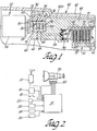
- Figure 1 is a diagrammatic view of a prior art multi-speed electronically controlled transmission.
- Figure 2 is a fragmentary sectional view of an integrated clutch housing and solenoid controlled valve of the present invention.
-
- Figure 2 shows a electronic transmission control 10 of the prior art including a selector lever and
position switch 12 and amicroprocessor 14 that receives a position switch signal from the selector lever andposition switch 12. Other monitors including aprogram switch 16; kick down switch 18 throttlevalve angle sensor 20;output rpm sensor 22;engine torque 24 andengine rpm 26; all of which direct input signals to themicroprocessor 14 for processing in a known manner and wherein themicroprocessor 14 is programmed in a known manner to produce output signals for selectively actuating a plurality of solenoid controlledvalves 30 that are grouped at one location on the underside of atransmission housing 32. - In the past the fluid pressure from a pump is directed through valves in the grouped solenoid controlled valves and then through a passage or external line to a point of use.
- As shown in Figure 1, the
transmission 40 of the present invention includes a plurality of friction couplings that are operated by a piston when a pressurized fluid is directed there against. One such friction coupling is shown in Figure 1. In order to avoid the lag problem of the prior art, thetransmission 40 includes anouter case 42 and one or more drop in brake orclutch housings 44 for one or morefriction disc packs 45. - In the illustrated arrangement the drop in
housing 44 has a splinedinner surface 46 that is connected to externally splinedplates 48. Theplates 48 are interleaved with internally splinedfriction discs hub portion 52 of a gear shift gear set (not shown) of a known type. - The drop in
housing 44 is secured with respect to theouter case 42 by being slidably engaged with an internal rib 42a on the interior surface thereof. - In accordance with the invention the drop in
housing 44 is integrated with a solenoid controlledvalve assembly 54. Asolenoid coil housing 56 is connected by abracket 58 to theouter end 60 of thehousing 44. In this embodiment, theouter end 60 is formed on anannular cover 62 closing abrake housing surface 64 that can have a plurality of suitable passages therein for feeding one or more brake units if desired. - The
cover 62 andhousing 44 have a valve track bore 66-formed therethrough. The bore 66 has asuitable seal gland 68 at the outboard end thereof. It receives a valve track 70 therein with spacedshoulders annular cavities housing 44 includes aninlet passage 82 connected to a source of pressurized actuating fluid directed tocavity 78. Thecavity 80 connects to anoutlet passage 84 in thehousing 44 that is communicated with apiston bore 86 therein. Thepiston bore 86 receives an actuating piston 88 that will be acted upon by pressure from the inlet 88 to engage thefriction disc pack 45. When the actuation pressure is connected to anexhaust 90 in thecontroller 54 the piston 88 is biased by areturn spring 92 so as to disengage theplates 48 andfriction discs 50 of thepack 45. The control of pressurized fluid within thecontroller 54 is by avalve element 92 of a known type with suitable lands thereon that seal against an internal bore 94 to control flow between theinlet passage 82, theoutlet passage 84 and theexhaust 90 viaopenings 96, 98 in the valve track 70 and as is known by those skilled in the prior art. - The solenoid operated
control valve 54 is connected to a high speed microprocessor and because it is directly integrated on thehousing 44 can be calibrated to accurately process outputs from such a microprocessor to produce a no lag response to brake engagement and release to produce a desired control of an associated gear set. - The solenoid operated
control valve 54 will respond to output signals to shift thevalve element 92 connected thereto within the valve track 70 such that pressurized flow from the transmission pump will be directly applied to the brakes such that the speed range of the multi-speed gear set can be adjusted smoothly in response to a variety of desired operating programs. - The invention has been described in an illustrative manner. It is to be understood that the terminology, which has been used, is intended to be in the nature of words of description rather than of limitation.
- Many modifications and variations of the invention are possible in light of the above teachings. Therefore, within the scope of the appended claims, the invention may be practiced other than as specifically described.
Claims (6)
- An electronically controlled transmission having a microprocessor (14); a transmission case (32) and a solenoid controlled valve (30) operated by signals from the microprocessor characterized by:a friction coupling housing (44) including an integrated solenoid controlled valve (54); said friction coupling housing (44) including a valve track (70) operably receiving a valve element (92) connected for operation by said integrated solenoid controlled valve; a friction disc pack (52) within said friction coupling housing; and a piston actuator (88) within said friction coupling housing pressurized by fluid flow across said valve element in response to electronic control signals from the microprocessor.
- The transmission of claim 1 wherein said friction coupling housing (44) is a drop in housing (42a) secured to the inside of said transmission casing.
- The transmission of claim 2 wherein said drop in housing includes a pressurizable inlet passage (82) and an outlet passage (84) therein configured to reduce hydraulic lag between solenoid controlled valve operation and imposition of hydraulic pressure on said piston actuator for the friction disc pack.
- The transmission of claim 1 said microprocessor being a high-speed microprocessor.
- The transmission of claim 1 wherein said friction disc pack is a gear-ratio control friction disc pack (52); said friction coupling housing encloses said gear-ratio control friction disc pack; said friction disc pack comprising a first plurality of discs (48) non-rotatably connected to said friction coupling housing and a second plurality of discs (50) non-rotatably connected to a second transmission component.
- The transmission of claim 1 wherein said solenoid controlled valve (54) and said valve track are located axially of said friction coupling housing and said friction coupling housing having a cover (62) and said solenoid controlled valve directly integrated into said cover.
Applications Claiming Priority (2)
| Application Number | Priority Date | Filing Date | Title |
|---|---|---|---|
| US09/379,402 US6209695B1 (en) | 1999-08-24 | 1999-08-24 | Multi-speed transmission with no lag electronically controlled valving |
| US379402 | 1999-08-24 |
Publications (3)
| Publication Number | Publication Date |
|---|---|
| EP1079150A2 true EP1079150A2 (en) | 2001-02-28 |
| EP1079150A3 EP1079150A3 (en) | 2004-01-07 |
| EP1079150B1 EP1079150B1 (en) | 2006-06-14 |
Family
ID=23497109
Family Applications (1)
| Application Number | Title | Priority Date | Filing Date |
|---|---|---|---|
| EP00306887A Expired - Lifetime EP1079150B1 (en) | 1999-08-24 | 2000-08-11 | Multi-speed transmission with no lag electronically controlled valving |
Country Status (5)
| Country | Link |
|---|---|
| US (1) | US6209695B1 (en) |
| EP (1) | EP1079150B1 (en) |
| JP (1) | JP2001099289A (en) |
| KR (1) | KR100624845B1 (en) |
| DE (1) | DE60028668T2 (en) |
Cited By (1)
| Publication number | Priority date | Publication date | Assignee | Title |
|---|---|---|---|---|
| KR100624845B1 (en) * | 1999-08-24 | 2006-09-14 | 보르그워너 인코퍼레이티드 | Multi-Speed Transmission with No Lag Electronically Controlled Valving |
Families Citing this family (17)
| Publication number | Priority date | Publication date | Assignee | Title |
|---|---|---|---|---|
| US6607062B1 (en) * | 2002-02-19 | 2003-08-19 | Torque Traction Technologies, Inc. | Piston assembly for hydraulically actuated friction coupling |
| US7316096B2 (en) * | 2004-06-30 | 2008-01-08 | Yale Security Inc. | Door operator |
| US8348628B2 (en) * | 2006-08-15 | 2013-01-08 | General Electric Company | System and method for monitoring a reciprocating compressor |
| CN101802335B (en) * | 2007-04-24 | 2013-11-06 | 耶鲁安全公司 | Door closer assembly |
| US8303463B2 (en) * | 2007-10-26 | 2012-11-06 | GM Global Technology Operations LLC | Method and apparatus to control clutch fill pressure in an electro-mechanical transmission |
| JP4924474B2 (en) * | 2008-02-27 | 2012-04-25 | マツダ株式会社 | Automatic transmission |
| US9289795B2 (en) * | 2008-07-01 | 2016-03-22 | Precision Coating Innovations, Llc | Pressurization coating systems, methods, and apparatuses |
| US9163446B2 (en) * | 2010-03-17 | 2015-10-20 | Yale Security Inc. | Door control apparatus |
| US8415902B2 (en) | 2010-04-16 | 2013-04-09 | Yale Security Inc. | Door closer with calibration mode |
| US8527101B2 (en) | 2010-04-16 | 2013-09-03 | Yale Security Inc. | Door closer assembly |
| US8547046B2 (en) | 2010-04-16 | 2013-10-01 | Yale Security Inc. | Door closer with self-powered control unit |
| US8779713B2 (en) * | 2010-04-16 | 2014-07-15 | Yale Security Inc. | Door closer with dynamically adjustable latch region parameters |
| US8773237B2 (en) | 2010-04-16 | 2014-07-08 | Yale Security Inc. | Door closer with teach mode |
| US8564235B2 (en) | 2010-04-16 | 2013-10-22 | Yale Security Inc. | Self-adjusting door closer |
| US20130303321A1 (en) * | 2012-05-11 | 2013-11-14 | Evan Earl Jacobson | Drive system having a planetary gear set |
| DE102021114788B4 (en) * | 2021-06-09 | 2023-11-02 | Schaeffler Technologies AG & Co. KG | Space-saving and safe control unit for the electro-hydraulic actuation of motor vehicle units |
| JP7185798B1 (en) | 2022-04-27 | 2022-12-07 | 大日精化工業株式会社 | Alumina-based thermally conductive round disk-like particles, method for producing same, thermally conductive composition, article, liquid composition, thermally conductive thin film, and electronic device member |
Citations (1)
| Publication number | Priority date | Publication date | Assignee | Title |
|---|---|---|---|---|
| US4750384A (en) | 1986-10-24 | 1988-06-14 | American Overdrive, Inc. | Overdrive transmission unit |
Family Cites Families (8)
| Publication number | Priority date | Publication date | Assignee | Title |
|---|---|---|---|---|
| US3138972A (en) * | 1959-12-08 | 1964-06-30 | J Rivoire Ets | Transmission mechanism for material handling vehicles |
| US4147245A (en) * | 1976-12-16 | 1979-04-03 | Tsentralny Nauchno-Issledovatelsky Avtomobilny I Avtomotorny Institut (Nami) | Hydraulically operated friction clutch |
| JPS6330657A (en) * | 1986-07-23 | 1988-02-09 | Daihatsu Motor Co Ltd | Power transmission |
| FR2693247B1 (en) * | 1992-07-03 | 1995-03-10 | Modern Automotive Technologies | Method for controlling a gear change and related gear transmission device, in particular for a vehicle. |
| JP3012426B2 (en) * | 1993-04-19 | 2000-02-21 | 株式会社クボタ | Transmission structure of agricultural work vehicle |
| FR2723775A1 (en) * | 1994-08-18 | 1996-02-23 | Antonov Automotive Europ | TRANSMISSION DEVICE, PARTICULARLY FOR VEHICLE, AND DRIVING METHOD RELATING THERETO. |
| DE19728228C2 (en) * | 1997-07-02 | 2000-06-29 | Zahnradfabrik Friedrichshafen | Automatic transmission |
| US6209695B1 (en) * | 1999-08-24 | 2001-04-03 | Borgwarner Inc. | Multi-speed transmission with no lag electronically controlled valving |
-
1999
- 1999-08-24 US US09/379,402 patent/US6209695B1/en not_active Expired - Lifetime
-
2000
- 2000-08-11 DE DE60028668T patent/DE60028668T2/en not_active Expired - Lifetime
- 2000-08-11 EP EP00306887A patent/EP1079150B1/en not_active Expired - Lifetime
- 2000-08-21 JP JP2000249840A patent/JP2001099289A/en active Pending
- 2000-08-24 KR KR1020000049211A patent/KR100624845B1/en not_active Expired - Fee Related
Patent Citations (1)
| Publication number | Priority date | Publication date | Assignee | Title |
|---|---|---|---|---|
| US4750384A (en) | 1986-10-24 | 1988-06-14 | American Overdrive, Inc. | Overdrive transmission unit |
Cited By (1)
| Publication number | Priority date | Publication date | Assignee | Title |
|---|---|---|---|---|
| KR100624845B1 (en) * | 1999-08-24 | 2006-09-14 | 보르그워너 인코퍼레이티드 | Multi-Speed Transmission with No Lag Electronically Controlled Valving |
Also Published As
| Publication number | Publication date |
|---|---|
| US6209695B1 (en) | 2001-04-03 |
| DE60028668T2 (en) | 2006-12-21 |
| EP1079150A3 (en) | 2004-01-07 |
| KR20010021406A (en) | 2001-03-15 |
| DE60028668D1 (en) | 2006-07-27 |
| JP2001099289A (en) | 2001-04-10 |
| EP1079150B1 (en) | 2006-06-14 |
| KR100624845B1 (en) | 2006-09-14 |
Similar Documents
| Publication | Publication Date | Title |
|---|---|---|
| US6209695B1 (en) | Multi-speed transmission with no lag electronically controlled valving | |
| US5613583A (en) | Slip control apparatus for motor vehicle lock-up clutch | |
| EP0038998B1 (en) | Electronic and hydraulic control system for automatic gear change transmission | |
| EP1371868B1 (en) | Electronic controlled coupling | |
| KR100334736B1 (en) | Actuator system for vehicular automated clutches with electric motor actuator and pressurized fluid override | |
| US7752935B2 (en) | Control system for a multi-speed transmission | |
| US20070093950A1 (en) | Electronic control system | |
| US4998604A (en) | Variable capacity control apparatus for an automotive torque converter clutch | |
| US6935204B2 (en) | Automated manual transmission and shift method | |
| US5850898A (en) | Method and device for the hydraulic actuation of a clutch, especially for automobiles | |
| US5569117A (en) | Slip control apparatus for motor vehicle lock-up clutch | |
| CN105697758A (en) | Electronic transmission range selection subsystem in a hydraulic control system for an automatic transmission | |
| US20140048374A1 (en) | Power transmitting apparatus | |
| EP1162392A2 (en) | Swap-shift control system for multiple ratio transmissions | |
| WO2008125950A1 (en) | Fail-safe mechanism for automatic transmission, and fail-safe valve provided in the fail-safe mechanism | |
| EP0783640B1 (en) | Automatic transmission system for automotive vehicle | |
| CA2390890C (en) | Electrohydraulic control system for controlling gearspeed changes in partially or fully automatic transmissions of vehicles | |
| US5415606A (en) | Synchronous shift coordination responsive to an O/D switch in an automatic transmission | |
| US4803901A (en) | Method and system for detecting the rotation rate of the output shaft of a torque converter | |
| US4787471A (en) | Power transmitting system for a four-wheel drive vehicle | |
| US20180172087A1 (en) | System and method for clutch actuation having electronic clutch actuator with integrated manual operation | |
| US7048104B2 (en) | Selective bypass of solenoid-controlled supply to friction elements of an automatic transmission | |
| US5637056A (en) | Automatic transmission system for automotive vehicle | |
| KR102341627B1 (en) | A PNEUMATIC ACTUATING DEVICE FOR ACTUATION TO BASED Dog clutch in manual transmission | |
| JP3897831B2 (en) | Hydraulic control device for automatic transmission |
Legal Events
| Date | Code | Title | Description |
|---|---|---|---|
| PUAI | Public reference made under article 153(3) epc to a published international application that has entered the european phase |
Free format text: ORIGINAL CODE: 0009012 |
|
| AK | Designated contracting states |
Kind code of ref document: A2 Designated state(s): AT BE CH CY DE DK ES FI FR GB GR IE IT LI LU MC NL PT SE |
|
| AX | Request for extension of the european patent |
Free format text: AL;LT;LV;MK;RO;SI |
|
| PUAL | Search report despatched |
Free format text: ORIGINAL CODE: 0009013 |
|
| AK | Designated contracting states |
Kind code of ref document: A3 Designated state(s): AT BE CH CY DE DK ES FI FR GB GR IE IT LI LU MC NL PT SE |
|
| AX | Request for extension of the european patent |
Extension state: AL LT LV MK RO SI |
|
| RIC1 | Information provided on ipc code assigned before grant |
Ipc: 7F 16H 63/30 B Ipc: 7F 16H 61/02 A Ipc: 7F 16D 48/06 B |
|
| 17P | Request for examination filed |
Effective date: 20040519 |
|
| RAP1 | Party data changed (applicant data changed or rights of an application transferred) |
Owner name: BORGWARNER INC. |
|
| AKX | Designation fees paid |
Designated state(s): DE FR GB IT |
|
| RAP1 | Party data changed (applicant data changed or rights of an application transferred) |
Owner name: BORGWARNER INC. |
|
| GRAP | Despatch of communication of intention to grant a patent |
Free format text: ORIGINAL CODE: EPIDOSNIGR1 |
|
| GRAS | Grant fee paid |
Free format text: ORIGINAL CODE: EPIDOSNIGR3 |
|
| GRAA | (expected) grant |
Free format text: ORIGINAL CODE: 0009210 |
|
| AK | Designated contracting states |
Kind code of ref document: B1 Designated state(s): DE FR GB IT |
|
| REG | Reference to a national code |
Ref country code: GB Ref legal event code: FG4D |
|
| REF | Corresponds to: |
Ref document number: 60028668 Country of ref document: DE Date of ref document: 20060727 Kind code of ref document: P |
|
| ET | Fr: translation filed | ||
| PLBE | No opposition filed within time limit |
Free format text: ORIGINAL CODE: 0009261 |
|
| STAA | Information on the status of an ep patent application or granted ep patent |
Free format text: STATUS: NO OPPOSITION FILED WITHIN TIME LIMIT |
|
| 26N | No opposition filed |
Effective date: 20070315 |
|
| PGFP | Annual fee paid to national office [announced via postgrant information from national office to epo] |
Ref country code: GB Payment date: 20090708 Year of fee payment: 10 |
|
| PGFP | Annual fee paid to national office [announced via postgrant information from national office to epo] |
Ref country code: IT Payment date: 20090812 Year of fee payment: 10 |
|
| GBPC | Gb: european patent ceased through non-payment of renewal fee |
Effective date: 20100811 |
|
| PG25 | Lapsed in a contracting state [announced via postgrant information from national office to epo] |
Ref country code: IT Free format text: LAPSE BECAUSE OF NON-PAYMENT OF DUE FEES Effective date: 20100811 |
|
| PG25 | Lapsed in a contracting state [announced via postgrant information from national office to epo] |
Ref country code: GB Free format text: LAPSE BECAUSE OF NON-PAYMENT OF DUE FEES Effective date: 20100811 |
|
| PGFP | Annual fee paid to national office [announced via postgrant information from national office to epo] |
Ref country code: DE Payment date: 20110831 Year of fee payment: 12 Ref country code: FR Payment date: 20110811 Year of fee payment: 12 |
|
| REG | Reference to a national code |
Ref country code: FR Ref legal event code: ST Effective date: 20130430 |
|
| PG25 | Lapsed in a contracting state [announced via postgrant information from national office to epo] |
Ref country code: DE Free format text: LAPSE BECAUSE OF NON-PAYMENT OF DUE FEES Effective date: 20130301 |
|
| PG25 | Lapsed in a contracting state [announced via postgrant information from national office to epo] |
Ref country code: FR Free format text: LAPSE BECAUSE OF NON-PAYMENT OF DUE FEES Effective date: 20120831 |
|
| REG | Reference to a national code |
Ref country code: DE Ref legal event code: R119 Ref document number: 60028668 Country of ref document: DE Effective date: 20130301 |