EP1079142A1 - Power transmission belt - Google Patents
Power transmission belt Download PDFInfo
- Publication number
- EP1079142A1 EP1079142A1 EP00117517A EP00117517A EP1079142A1 EP 1079142 A1 EP1079142 A1 EP 1079142A1 EP 00117517 A EP00117517 A EP 00117517A EP 00117517 A EP00117517 A EP 00117517A EP 1079142 A1 EP1079142 A1 EP 1079142A1
- Authority
- EP
- European Patent Office
- Prior art keywords
- fabric
- power transmission
- transmission belt
- flock
- belt
- Prior art date
- Legal status (The legal status is an assumption and is not a legal conclusion. Google has not performed a legal analysis and makes no representation as to the accuracy of the status listed.)
- Granted
Links
- 230000005540 biological transmission Effects 0.000 title claims abstract description 21
- 239000004744 fabric Substances 0.000 claims abstract description 40
- 230000006835 compression Effects 0.000 claims abstract description 11
- 238000007906 compression Methods 0.000 claims abstract description 11
- 244000144992 flock Species 0.000 claims description 30
- 239000000853 adhesive Substances 0.000 claims description 27
- 230000001070 adhesive effect Effects 0.000 claims description 27
- 239000000835 fiber Substances 0.000 claims description 23
- 229920000728 polyester Polymers 0.000 claims description 12
- 229920000742 Cotton Polymers 0.000 claims description 11
- 239000004677 Nylon Substances 0.000 claims description 9
- 229920000297 Rayon Polymers 0.000 claims description 9
- 229920001778 nylon Polymers 0.000 claims description 9
- 239000002964 rayon Substances 0.000 claims description 9
- 229920003235 aromatic polyamide Polymers 0.000 claims description 6
- 239000004760 aramid Substances 0.000 claims description 5
- 239000004814 polyurethane Substances 0.000 claims description 5
- 239000000463 material Substances 0.000 claims description 4
- 239000000203 mixture Substances 0.000 claims description 4
- -1 polytetrafluoroethylene Polymers 0.000 claims description 4
- 229920002635 polyurethane Polymers 0.000 claims description 4
- 229920000049 Carbon (fiber) Polymers 0.000 claims description 3
- 239000004917 carbon fiber Substances 0.000 claims description 3
- 239000011152 fibreglass Substances 0.000 claims description 3
- VNWKTOKETHGBQD-UHFFFAOYSA-N methane Chemical compound C VNWKTOKETHGBQD-UHFFFAOYSA-N 0.000 claims description 3
- 230000001360 synchronised effect Effects 0.000 claims description 3
- NIXOWILDQLNWCW-UHFFFAOYSA-N acrylic acid group Chemical group C(C=C)(=O)O NIXOWILDQLNWCW-UHFFFAOYSA-N 0.000 claims description 2
- 230000002457 bidirectional effect Effects 0.000 claims description 2
- 229920001343 polytetrafluoroethylene Polymers 0.000 claims description 2
- 239000004810 polytetrafluoroethylene Substances 0.000 claims description 2
- 238000000034 method Methods 0.000 description 14
- 229920001971 elastomer Polymers 0.000 description 8
- 239000000806 elastomer Substances 0.000 description 6
- 239000010410 layer Substances 0.000 description 5
- 229920001577 copolymer Polymers 0.000 description 4
- 239000000758 substrate Substances 0.000 description 4
- 244000043261 Hevea brasiliensis Species 0.000 description 3
- 229920000459 Nitrile rubber Polymers 0.000 description 3
- 229920006168 hydrated nitrile rubber Polymers 0.000 description 3
- 229920003052 natural elastomer Polymers 0.000 description 3
- 229920001194 natural rubber Polymers 0.000 description 3
- 229920000642 polymer Polymers 0.000 description 3
- 229920003048 styrene butadiene rubber Polymers 0.000 description 3
- 229920002943 EPDM rubber Polymers 0.000 description 2
- 239000005062 Polybutadiene Substances 0.000 description 2
- 125000003262 carboxylic acid ester group Chemical class [H]C([H])([*:2])OC(=O)C([H])([H])[*:1] 0.000 description 2
- 229920006229 ethylene acrylic elastomer Polymers 0.000 description 2
- 239000004816 latex Substances 0.000 description 2
- 229920000126 latex Polymers 0.000 description 2
- 229920001084 poly(chloroprene) Polymers 0.000 description 2
- 229920002857 polybutadiene Polymers 0.000 description 2
- 229920001195 polyisoprene Polymers 0.000 description 2
- 239000005060 rubber Substances 0.000 description 2
- 150000003751 zinc Chemical class 0.000 description 2
- KGIGUEBEKRSTEW-UHFFFAOYSA-N 2-vinylpyridine Chemical compound C=CC1=CC=CC=N1 KGIGUEBEKRSTEW-UHFFFAOYSA-N 0.000 description 1
- 229920003189 Nylon 4,6 Polymers 0.000 description 1
- 229920002292 Nylon 6 Polymers 0.000 description 1
- 229920002302 Nylon 6,6 Polymers 0.000 description 1
- 229910000831 Steel Inorganic materials 0.000 description 1
- 239000012790 adhesive layer Substances 0.000 description 1
- 230000001680 brushing effect Effects 0.000 description 1
- 239000004568 cement Substances 0.000 description 1
- 230000000295 complement effect Effects 0.000 description 1
- 238000005336 cracking Methods 0.000 description 1
- 238000005520 cutting process Methods 0.000 description 1
- 238000007598 dipping method Methods 0.000 description 1
- 230000005684 electric field Effects 0.000 description 1
- 230000005611 electricity Effects 0.000 description 1
- 230000005686 electrostatic field Effects 0.000 description 1
- 239000000839 emulsion Substances 0.000 description 1
- 230000005484 gravity Effects 0.000 description 1
- 239000004615 ingredient Substances 0.000 description 1
- 239000012948 isocyanate Substances 0.000 description 1
- 238000004519 manufacturing process Methods 0.000 description 1
- 239000011159 matrix material Substances 0.000 description 1
- 229920002577 polybenzoxazole Polymers 0.000 description 1
- 229920003225 polyurethane elastomer Polymers 0.000 description 1
- 229920002689 polyvinyl acetate Polymers 0.000 description 1
- 239000011118 polyvinyl acetate Substances 0.000 description 1
- 229920000915 polyvinyl chloride Polymers 0.000 description 1
- 239000004800 polyvinyl chloride Substances 0.000 description 1
- 230000002028 premature Effects 0.000 description 1
- 239000011347 resin Substances 0.000 description 1
- 229920005989 resin Polymers 0.000 description 1
- 238000012216 screening Methods 0.000 description 1
- 230000035939 shock Effects 0.000 description 1
- 239000002904 solvent Substances 0.000 description 1
- 239000007921 spray Substances 0.000 description 1
- 238000005507 spraying Methods 0.000 description 1
- 230000003068 static effect Effects 0.000 description 1
- 239000010959 steel Substances 0.000 description 1
Images

Classifications
-
- F—MECHANICAL ENGINEERING; LIGHTING; HEATING; WEAPONS; BLASTING
- F16—ENGINEERING ELEMENTS AND UNITS; GENERAL MEASURES FOR PRODUCING AND MAINTAINING EFFECTIVE FUNCTIONING OF MACHINES OR INSTALLATIONS; THERMAL INSULATION IN GENERAL
- F16G—BELTS, CABLES, OR ROPES, PREDOMINANTLY USED FOR DRIVING PURPOSES; CHAINS; FITTINGS PREDOMINANTLY USED THEREFOR
- F16G5/00—V-belts, i.e. belts of tapered cross-section
- F16G5/04—V-belts, i.e. belts of tapered cross-section made of rubber
- F16G5/06—V-belts, i.e. belts of tapered cross-section made of rubber with reinforcement bonded by the rubber
-
- F—MECHANICAL ENGINEERING; LIGHTING; HEATING; WEAPONS; BLASTING
- F16—ENGINEERING ELEMENTS AND UNITS; GENERAL MEASURES FOR PRODUCING AND MAINTAINING EFFECTIVE FUNCTIONING OF MACHINES OR INSTALLATIONS; THERMAL INSULATION IN GENERAL
- F16G—BELTS, CABLES, OR ROPES, PREDOMINANTLY USED FOR DRIVING PURPOSES; CHAINS; FITTINGS PREDOMINANTLY USED THEREFOR
- F16G1/00—Driving-belts
- F16G1/06—Driving-belts made of rubber
- F16G1/08—Driving-belts made of rubber with reinforcement bonded by the rubber
-
- F—MECHANICAL ENGINEERING; LIGHTING; HEATING; WEAPONS; BLASTING
- F16—ENGINEERING ELEMENTS AND UNITS; GENERAL MEASURES FOR PRODUCING AND MAINTAINING EFFECTIVE FUNCTIONING OF MACHINES OR INSTALLATIONS; THERMAL INSULATION IN GENERAL
- F16G—BELTS, CABLES, OR ROPES, PREDOMINANTLY USED FOR DRIVING PURPOSES; CHAINS; FITTINGS PREDOMINANTLY USED THEREFOR
- F16G5/00—V-belts, i.e. belts of tapered cross-section
- F16G5/20—V-belts, i.e. belts of tapered cross-section with a contact surface of special shape, e.g. toothed
Definitions
- Power transmission belts such as V-ribbed belts
- V-ribbed belts are normally wound around pulleys that are complementary to the inner surface of the belt. Power transmission is effected by making use of the frictional forces generated between the surfaces.
- a splice is created at the point where the two ends of the belt are joined. In those instances where the flock is embedded into the elastomer, the fibers have been observed to become lodged in the splice and contribute to undesirable cracking and premature failure of the belt. Therefore, there exists a need to obtain the advantages of improving the frictional properties of power transmission belts in the absence of embedding the fibers into the elastomeric drive surface of the belt.
- the present invention relates to a power transmission belt that is characterized by a flocked fabric on the drive surface which increases the coefficient of friction.
- an endless power transmission belt comprising
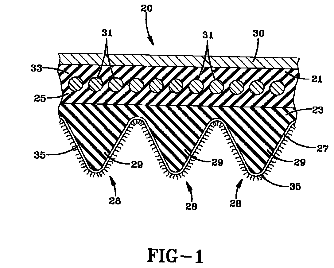
- FIG. 1 of the drawing illustrates an endless power transmission belt structure or belt of this invention which is designated generally by the reference numeral 20.
- the belt 20 is particularly adapted to be used in associated sheaves in accordance with techniques known in the art.
- the belt is particularly suited for use in short center drives, exercise equipment, automotive drives, farm equipment, so-called torque sensing drives, application where shock loads of varying belt tension are imposed on the belt, applications where the belt is operated at variable speeds, applications where the belt is spring-loaded to control its tension, and the like.
- the belt 20 comprises a tension section 21, a compression section 23 and a load-carrying section 25 disposed between the tension section 21 and compression section 23.
- the belt 20 also has an inside ply or inner fabric layer 27, adhered to a drive surface 28 and three ribs 29 or Vs which are fabric-coated.
- the belt 20 of Figure 1 has a fabric backing 30.
- the fabric backing 30 may be bidirectional, non-woven, woven or knitted fabric.
- the fabric backing layer 30 may be frictioned, dipped, spread, coated or laminated.
- the fabric facing layer 27 may be made from a bi-directional, non-woven, woven or knitted fabric.
- the preferred fabric layer 27 is non-woven.
- the fabrics to be flocked for use in the present invention are made of conventional materials including nylon (such as nylon 4,6, nylon 6,6 and nylon 6), polyester/rayon, cotton, cotton/rayon, polyester, cotton/polyester, nylon/polyester, cotton/nylon, LycraTM (segmented polyurethane), aramid, rayon, and the like.
- nylon such as nylon 4,6, nylon 6,6 and nylon 6
- polyester/rayon cotton, cotton/rayon
- polyester cotton/polyester, nylon/polyester, cotton/nylon
- LycraTM spun polyurethane
- aramid rayon
- rayon and the like.
- the fabric is made of polyester/rayon.
- the load-carrying section 25 has load-carrying means in the form of load-carrying cords 31 or filaments which are suitably embedded in an elastomeric cushion or matrix 33 in accordance with techniques which are well known in the art.
- the cords 31 or filaments may be made of any suitable material known and used in the art. Representative examples of such materials include aramids, fiberglass, nylon, polyester, cotton, steel, carbon fiber and polybenzoxazole.
- the drive surface 28 of the belt 20 of Figure 1 is multi-V-grooved.
- the belts of the present invention also include those belts where the drive surface of the belt may be flat, single V-grooved and synchronous.
- Representative examples of synchronous include belts having trapezoidal or curvilinear teeth.
- the tooth design may have a helical offset tooth design such as shown in US-A- 5,209,705 and 5,421,789.
- the belt 20 of Figure 1 has one drive surface 28.
- the belt may have two drive surfaces (not shown) such as in a double-sided belt.
- one or both drive surfaces may be coated with the flocked fabric as described herein.
- the belt 20 has one drive surface.
- the rubber compositions for use in the tension section 21 and compression section 22 may be the same or different.
- Conventional elastomers which may be used in one or both of these sections include natural rubber, polychloroprene, acrylonitrile-butadiene copolymers (NBR), polyisoprene, zinc salts of unsaturated carboxylic acid ester grafted hydrogenated nitrile butadiene elastomers, styrene-butadiene rubbers, polybutadiene, EPDM, hydrogenated acrylonitrile-butadiene copolymers (HNBR), polyurethane, elastomers marketed under the VitonTM designation and ethylene-acrylic elastomers sold under the name VAMAC and blends thereof.
- NBR acrylonitrile-butadiene copolymers
- HNBR hydrogenated acrylonitrile-butadiene copolymers
- the surface of the fabric 27 on the drive surface is covered with a short fiber flock 35 by means of an adhesive to directly adhere the flock 35 to the fabric 27.
- the short fiber flock 35 for use in this invention is characterized by a length range of from 0.12 mm to 9.6 mm and a denier (grams per 9000 meters) of 0.5 to 50.
- the length (measured in the longest direction) ranges from 0.25 to 6 mm and the denier ranges from 0.8 to 25.
- the most preferred flock has a length of from 0.5 mm to 3 mm and a denier of from 1 to 3.
- the short fiber flock 35 is uniformly distributed directly on the surface of the drive surface 28 of the power transmission belt 20.
- the short fiber flock 35 may be derived from cotton, carbon fiber, rayon, acrylic, TeflonTM (polytetrafluoroethylene), nylon, polyester, aromatic polyamide (aramid), fiberglass and mixtures thereof.
- the flock 35 may be produced by means known to those skilled in the art, such as by reducing the length of a mass of already short fibers by cutting or grinding. The ground fibers are then graded by screening to eliminate overly long fibers.
- the particular adhesive that may be used may vary.
- One conventional adhesive which may be used is known in the art as a RFL (resorcinol-formaldehyde-latex) adhesive.
- the RFL adhesives comprise a polymer latex which may be based on natural rubber, styrene-butadiene rubber, acrylonitrile-butadiene rubber (NBR), hydrogenated acrylonitrile-butadiene rubber (HNBR) and vinyl pyridine.
- An optional ingredient to the RFL is an isocyanate compound.
- adhesives are the resin emulsions sold by BF Goodrich which include polyvinyl acetate, polyacrylic, polyvinyl chloride and polyurethane.
- Cement solutions (organic) of polymers may also be used as an adhesive.
- Representative polymers include natural rubber, polychloroprene, acrylonitrile-butadiene copolymers, polyisoprene, zinc salts of unsaturated carboxylic acid ester grafted hydrogenated nitrile butadiene elastomers, styrene-butadiene rubbers, polybutadiene, EPDM, hydrogenated acrylonitrile-butadiene copolymers, polyurethane and ethylene-acrylic elastomers.
- the adhesive is first applied to the fabric 27 and the flock 35 is thereafter applied.
- the adhesive may be applied to the fabric either before or after being adhered to the compression section 23 of the belt.
- the adhesive and flock are first applied to the fabric 27 and thereafter the flock-treated fabric 27 is applied to the belt 20.
- flock adhesives There are many methods available for applying flock adhesives.
- the adhesive may be applied with a knife, reverse roll or roll-over-platform coaters. Engraved rolls, spray applicators and rotary screen printers may also be used.
- Other flock adhesive application methods include silk-screen, dipping, brushing and spraying.
- the thickness of the adhesive layer may vary. Generally speaking, the thickness of the adhesive may range from 0.05 mm to 1 mm. Preferably, the thickness of the adhesive will range from 0.05 to 0.4 mm.
- the short fiber flock 35 may be applied to the adhesive-treated fabric in a number of means and thereafter the flocked fabric applied to as uncured belt.
- the flock may be applied to the adhesive-coated surface either mechanically, electrostatically or by means of a combination of both techniques.
- Mechanical flocking can be further divided into windblown and beater-bar methods.
- Electrostatic flocking sometimes incorporates a pneumatic process to propel fibers toward a surface in a windstream.
- the beater bar method involves passage of the adhesive-treated fabric over a series of polygonal rollers that rapidly rotate to vibrate the substrate. The vibration is used to drive the fiber onto the adhesive. Fibers may be fed to the substrate by gravity from a flock module.
- Windblown mechanical flocking uses an airstream to deliver the flock to the adhesive-treated fabric.
- Electrostatic flocking is a known technique which utilizes a field of static electricity to orient fibers and promote their perpendicular alignment. This technique is recommended with longer fibers.
- the adhesive-coated substrate passes between the potentials of a high voltage electrostatic field.
- An electrode is utilized to give the flock a charge.
- the charged fibers become aligned with the electric field lines of force.
- the ground potential is formed by the substrate and/or the grounded parts of the machine.
- the flock is thus attracted to the adhesive where it becomes embedded.
- the windblown and electrostatic methods may be utilized simultaneously through pneumatic/electrostatic flocking. With this method, an airstream containing the fibers are directed through a nozzle. At the exit of the nozzle, a charge orients the fibers according to field lines.
- the short fiber flock may be applied to the fabric of the belt in a variety of levels.
- the amount of flock may range from 0.05 kg/m 2 to 1.0 kg/m 2 .
- the preferred level ranges from 0.1 kg/m 2 to 0.5 kg/m 2 .
- the flocked fabric may be cleaned by suction and the like. Thereafter, the adhesive is dried.
- power transmission belts may be built on a drum device.
- the backing is applied to drum as a sheet.
- any tension section is applied as a sheet followed by spiralling onto the drum the cord or tensile members (load-carrying section).
- the cushion section is applied followed by the flocked fabric.
- the assembled laminate or slab is then removed from the drum, placed in a mold, cured and cut into the belts in a manner known to those skilled in the art.
Landscapes
- Engineering & Computer Science (AREA)
- General Engineering & Computer Science (AREA)
- Mechanical Engineering (AREA)
- Treatments For Attaching Organic Compounds To Fibrous Goods (AREA)
- Woven Fabrics (AREA)
- Devices For Conveying Motion By Means Of Endless Flexible Members (AREA)
- Laminated Bodies (AREA)
- Belt Conveyors (AREA)
Abstract
Description
- Power transmission belts, such as V-ribbed belts, are normally wound around pulleys that are complementary to the inner surface of the belt. Power transmission is effected by making use of the frictional forces generated between the surfaces. To increase such frictional forces, particularly in wet conditions, it is known to embed short fibers in the elastomer of the drive surface in the compression section of the belt. Unfortunately, in the manufacture of rubber belts, a splice is created at the point where the two ends of the belt are joined. In those instances where the flock is embedded into the elastomer, the fibers have been observed to become lodged in the splice and contribute to undesirable cracking and premature failure of the belt. Therefore, there exists a need to obtain the advantages of improving the frictional properties of power transmission belts in the absence of embedding the fibers into the elastomeric drive surface of the belt.
- The present invention relates to a power transmission belt that is characterized by a flocked fabric on the drive surface which increases the coefficient of friction.
- The accompanying figure shows embodiments of this invention in which
- Figure 1 is a fragmentary perspective view illustrating one embodiment of an endless power transmission belt of this invention.
-
- There is disclosed an endless power transmission belt comprising
- (a) a tension section;
- (b) a compression section;
- (c) a load-carrying section disposed between said tension section and cushion section; and
- (d) at least one drive surface having a flocked fabric facing layer bonded to an outer surface of the belt.
-
- Reference is now made to Figure 1 of the drawing which illustrates an endless power transmission belt structure or belt of this invention which is designated generally by the
reference numeral 20. Thebelt 20 is particularly adapted to be used in associated sheaves in accordance with techniques known in the art. The belt is particularly suited for use in short center drives, exercise equipment, automotive drives, farm equipment, so-called torque sensing drives, application where shock loads of varying belt tension are imposed on the belt, applications where the belt is operated at variable speeds, applications where the belt is spring-loaded to control its tension, and the like. - The
belt 20 comprises atension section 21, acompression section 23 and a load-carryingsection 25 disposed between thetension section 21 andcompression section 23. Thebelt 20 also has an inside ply orinner fabric layer 27, adhered to adrive surface 28 and threeribs 29 or Vs which are fabric-coated. Thebelt 20 of Figure 1 has a fabric backing 30. The fabric backing 30 may be bidirectional, non-woven, woven or knitted fabric. Thefabric backing layer 30 may be frictioned, dipped, spread, coated or laminated. - The
fabric facing layer 27 may be made from a bi-directional, non-woven, woven or knitted fabric. The preferredfabric layer 27 is non-woven. - The fabrics to be flocked for use in the present invention are made of conventional materials including nylon (such as nylon 4,6, nylon 6,6 and nylon 6), polyester/rayon, cotton, cotton/rayon, polyester, cotton/polyester, nylon/polyester, cotton/nylon, Lycra™ (segmented polyurethane), aramid, rayon, and the like. Preferably, the fabric is made of polyester/rayon.
- The load-carrying
section 25 has load-carrying means in the form of load-carryingcords 31 or filaments which are suitably embedded in an elastomeric cushion ormatrix 33 in accordance with techniques which are well known in the art. Thecords 31 or filaments may be made of any suitable material known and used in the art. Representative examples of such materials include aramids, fiberglass, nylon, polyester, cotton, steel, carbon fiber and polybenzoxazole. - The
drive surface 28 of thebelt 20 of Figure 1 is multi-V-grooved. In accordance with other embodiments and as discussed later, it is contemplated herein the belts of the present invention also include those belts where the drive surface of the belt may be flat, single V-grooved and synchronous. Representative examples of synchronous include belts having trapezoidal or curvilinear teeth. The tooth design may have a helical offset tooth design such as shown in US-A- 5,209,705 and 5,421,789. - The
belt 20 of Figure 1 has onedrive surface 28. However, it is contemplated herein that the belt may have two drive surfaces (not shown) such as in a double-sided belt. In such an instance, one or both drive surfaces may be coated with the flocked fabric as described herein. Preferably, thebelt 20 has one drive surface. - The rubber compositions for use in the
tension section 21 and compression section 22 may be the same or different. Conventional elastomers which may be used in one or both of these sections include natural rubber, polychloroprene, acrylonitrile-butadiene copolymers (NBR), polyisoprene, zinc salts of unsaturated carboxylic acid ester grafted hydrogenated nitrile butadiene elastomers, styrene-butadiene rubbers, polybutadiene, EPDM, hydrogenated acrylonitrile-butadiene copolymers (HNBR), polyurethane, elastomers marketed under the Viton™ designation and ethylene-acrylic elastomers sold under the name VAMAC and blends thereof. - The surface of the
fabric 27 on the drive surface is covered with ashort fiber flock 35 by means of an adhesive to directly adhere theflock 35 to thefabric 27. Theshort fiber flock 35 for use in this invention is characterized by a length range of from 0.12 mm to 9.6 mm and a denier (grams per 9000 meters) of 0.5 to 50. Preferably, the length (measured in the longest direction) ranges from 0.25 to 6 mm and the denier ranges from 0.8 to 25. The most preferred flock has a length of from 0.5 mm to 3 mm and a denier of from 1 to 3. Theshort fiber flock 35 is uniformly distributed directly on the surface of thedrive surface 28 of thepower transmission belt 20. Unlike the prior art belts, the flock is not dispersed in the elastomer of thecompression section 23 but rather the flock is separated from the elastomer in thecompression section 23 by thefabric 27. Theshort fiber flock 35 may be derived from cotton, carbon fiber, rayon, acrylic, Teflon™ (polytetrafluoroethylene), nylon, polyester, aromatic polyamide (aramid), fiberglass and mixtures thereof. Theflock 35 may be produced by means known to those skilled in the art, such as by reducing the length of a mass of already short fibers by cutting or grinding. The ground fibers are then graded by screening to eliminate overly long fibers. - There are many types of water- and solvent-based adhesives which may be used to adhere the flock to the surface of the fabric. The particular adhesive that may be used may vary. One conventional adhesive which may be used is known in the art as a RFL (resorcinol-formaldehyde-latex) adhesive. The RFL adhesives comprise a polymer latex which may be based on natural rubber, styrene-butadiene rubber, acrylonitrile-butadiene rubber (NBR), hydrogenated acrylonitrile-butadiene rubber (HNBR) and vinyl pyridine. An optional ingredient to the RFL is an isocyanate compound. Additional examples of conventional adhesives are the resin emulsions sold by BF Goodrich which include polyvinyl acetate, polyacrylic, polyvinyl chloride and polyurethane. Cement solutions (organic) of polymers may also be used as an adhesive. Representative polymers include natural rubber, polychloroprene, acrylonitrile-butadiene copolymers, polyisoprene, zinc salts of unsaturated carboxylic acid ester grafted hydrogenated nitrile butadiene elastomers, styrene-butadiene rubbers, polybutadiene, EPDM, hydrogenated acrylonitrile-butadiene copolymers, polyurethane and ethylene-acrylic elastomers.
- The adhesive is first applied to the
fabric 27 and theflock 35 is thereafter applied. The adhesive may be applied to the fabric either before or after being adhered to thecompression section 23 of the belt. Preferably, the adhesive and flock are first applied to thefabric 27 and thereafter the flock-treatedfabric 27 is applied to thebelt 20. - There are many methods available for applying flock adhesives. In roll-to-roll flocking, the adhesive may be applied with a knife, reverse roll or roll-over-platform coaters. Engraved rolls, spray applicators and rotary screen printers may also be used. Other flock adhesive application methods include silk-screen, dipping, brushing and spraying.
- The thickness of the adhesive layer may vary. Generally speaking, the thickness of the adhesive may range from 0.05 mm to 1 mm. Preferably, the thickness of the adhesive will range from 0.05 to 0.4 mm.
- The
short fiber flock 35 may be applied to the adhesive-treated fabric in a number of means and thereafter the flocked fabric applied to as uncured belt. The flock may be applied to the adhesive-coated surface either mechanically, electrostatically or by means of a combination of both techniques. Mechanical flocking can be further divided into windblown and beater-bar methods. Electrostatic flocking sometimes incorporates a pneumatic process to propel fibers toward a surface in a windstream. The beater bar method involves passage of the adhesive-treated fabric over a series of polygonal rollers that rapidly rotate to vibrate the substrate. The vibration is used to drive the fiber onto the adhesive. Fibers may be fed to the substrate by gravity from a flock module. Windblown mechanical flocking uses an airstream to deliver the flock to the adhesive-treated fabric. Electrostatic flocking is a known technique which utilizes a field of static electricity to orient fibers and promote their perpendicular alignment. This technique is recommended with longer fibers. In the electrostatic technique, the adhesive-coated substrate passes between the potentials of a high voltage electrostatic field. An electrode is utilized to give the flock a charge. The charged fibers become aligned with the electric field lines of force. The ground potential is formed by the substrate and/or the grounded parts of the machine. The flock is thus attracted to the adhesive where it becomes embedded. Via this method, most of the fibers adhering to the adhesive-coated surface are perpendicular to it. The windblown and electrostatic methods may be utilized simultaneously through pneumatic/electrostatic flocking. With this method, an airstream containing the fibers are directed through a nozzle. At the exit of the nozzle, a charge orients the fibers according to field lines. - The short fiber flock may be applied to the fabric of the belt in a variety of levels. For example, the amount of flock may range from 0.05 kg/m2 to 1.0 kg/m2. The preferred level ranges from 0.1 kg/m2 to 0.5 kg/m2.
- After the fiber flock has been applied, the flocked fabric may be cleaned by suction and the like. Thereafter, the adhesive is dried.
- As known to those skilled in the art, power transmission belts may be built on a drum device. First, the backing is applied to drum as a sheet. Next, any tension section is applied as a sheet followed by spiralling onto the drum the cord or tensile members (load-carrying section). Thereafter, the cushion section is applied followed by the flocked fabric. The assembled laminate or slab is then removed from the drum, placed in a mold, cured and cut into the belts in a manner known to those skilled in the art.
Claims (10)
- An endless power transmission belt (20) comprising(a) a tension section (21);(b) a compressoin section (23);(c) a load-carrying section (25) disposed between said tension section and compression section (23); and(d) at least one drive surface (28) having a flocked fabric facing layer (35) bonded to an outer surface of the belt.
- The power transmission belt (20) of claim 1 characterized in that said fabric is selected from the group consisting of bidirectional, non-woven, woven and knitted fabric.
- The power transmission belt (20) of claim 1 characterized in that the flock on said fabric is adhered to said fabric by the use of an adhesive.
- The power transmission belt (20) of claim 3 characterized in that the thickness of said adhesive ranges from 0.05 to 1 mm.
- The power transmission belt (20) of claim 1 characterized in that the flock on said fabric is selected from the group consisting of cotton, carbon fiber, rayon, acrylic, polytetrafluoroethylene, nylon, polyester, aromatic polyamide, fiberglass and mixtures thereof.
- The power transmission belt (20) of claim 1 characterized in that the length of the flock on said fabric ranges from 0.12 mm to 9.6 mm.
- The power transmission belt (20) of claim 1 characterized in that the denier of the flock on said fabric ranges from 0.5 to 50.
- The power transmission belt (20) of claim 1 characterized in that the fabric that is flocked is made of a material selected from the group consisting of nylon, polyester/rayon, cotton, cotton/rayon, polyester, cotton/polyester, nylon/polyester, cotton/nylon, segmented polyurethane, aramid and rayon.
- The power transmission belt (20) of claim 1 characterized in that said short fiber flock is present on said fabric in an amount ranging from 0.05 to 1.0 kg/m2.
- The power transmission belt (20) of claim 1 characterized in that the drive surface (28) of the belt is selected from the group consisting of flat, single V-grooved, multi-V-grooved and synchronous.
Applications Claiming Priority (2)
| Application Number | Priority Date | Filing Date | Title |
|---|---|---|---|
| US15087199P | 1999-08-26 | 1999-08-26 | |
| US150871P | 1999-08-26 |
Publications (2)
| Publication Number | Publication Date |
|---|---|
| EP1079142A1 true EP1079142A1 (en) | 2001-02-28 |
| EP1079142B1 EP1079142B1 (en) | 2006-04-05 |
Family
ID=22536357
Family Applications (1)
| Application Number | Title | Priority Date | Filing Date |
|---|---|---|---|
| EP00117517A Expired - Lifetime EP1079142B1 (en) | 1999-08-26 | 2000-08-14 | Method to manufacture a power transmission belt |
Country Status (6)
| Country | Link |
|---|---|
| US (1) | US6561937B1 (en) |
| EP (1) | EP1079142B1 (en) |
| JP (1) | JP2001082549A (en) |
| BR (1) | BR0003688A (en) |
| CA (1) | CA2313421A1 (en) |
| DE (1) | DE60027096T2 (en) |
Cited By (2)
| Publication number | Priority date | Publication date | Assignee | Title |
|---|---|---|---|---|
| WO2001075330A1 (en) * | 2000-04-03 | 2001-10-11 | Contitech Antriebssysteme Gmbh | Frictionally engaged driving belt |
| DE102006007509B4 (en) * | 2006-02-16 | 2009-01-22 | Contitech Antriebssysteme Gmbh | V-ribbed belt with improved noise behavior |
Families Citing this family (18)
| Publication number | Priority date | Publication date | Assignee | Title |
|---|---|---|---|---|
| DE10144547A1 (en) * | 2001-09-10 | 2003-03-27 | Arntz Beteiligungs Gmbh & Co | Toothed belt for force transmission comprises a layer of twisted cords which consist of polyester-polyacrylate fibers or filaments produced out of liquid-crystal polymers by a melt-spinning process |
| ES2269574T3 (en) * | 2002-09-07 | 2007-04-01 | Contitech Antriebssysteme Gmbh | BELT OF TRAPEZOID NERVES AND PROCEDURE FOR MANUFACTURING. |
| US8030404B2 (en) * | 2004-12-31 | 2011-10-04 | Veyance Technologies, Inc. | Power transmission products having enhanced properties |
| US20060148989A1 (en) * | 2004-12-31 | 2006-07-06 | George Burrowes | Power transmission belts having enhanced properties |
| US7695386B2 (en) * | 2005-06-16 | 2010-04-13 | Veyance Technologies, Inc. | Fabric treatment for reinforced elastomeric articles |
| US7683136B2 (en) * | 2005-06-16 | 2010-03-23 | VeyanceTechnologies, Inc. | Elastomeric compound |
| CN100534262C (en) * | 2005-09-16 | 2009-08-26 | 富葵精密组件(深圳)有限公司 | Film hole forming device and method |
| KR101569937B1 (en) * | 2006-01-19 | 2015-11-17 | 데이코 유로페 에스.알.엘. 콘 유니코 소시오 | toothed belt and timing control system |
| US8197372B2 (en) | 2006-04-07 | 2012-06-12 | The Gates Corporation | Power transmission belt |
| JP2008069008A (en) * | 2006-08-11 | 2008-03-27 | Inventio Ag | Belt of elevator device, method of manufacturing the belt, and elevator device having the belt |
| US7325864B1 (en) * | 2006-08-28 | 2008-02-05 | Valentin Echeverria | Rotating automotive grille assembly |
| EP2201266B1 (en) | 2007-09-14 | 2018-10-31 | Gates Corporation | V-ribbed belt and method for manufacturing same |
| JP4989556B2 (en) * | 2008-05-26 | 2012-08-01 | 三ツ星ベルト株式会社 | V-ribbed belt |
| CN102428296B (en) * | 2009-05-20 | 2015-03-04 | 阪东化学株式会社 | Friction drive belt and manufacturing method thereof |
| JP5367006B2 (en) * | 2011-03-31 | 2013-12-11 | ゲイツ・ユニッタ・アジア株式会社 | Friction transmission belt |
| US9157503B2 (en) * | 2013-03-14 | 2015-10-13 | Dayco Ip Holdings, Llc | V-ribbed belt with spaced rib flank reinforcement |
| DE102014003564B4 (en) * | 2014-03-13 | 2015-12-17 | Arntz Beteiligungs Gmbh & Co. Kg | V-ribbed belt and method for indicating a state of wear on a V-ribbed belt |
| ES2748214B2 (en) | 2019-06-13 | 2022-02-01 | Gates Corp | POWER TRANSMISSION BELT WITH STRIPED SURFACE AND A STRIPED COVERING FABRIC. |
Citations (6)
| Publication number | Priority date | Publication date | Assignee | Title |
|---|---|---|---|---|
| GB868916A (en) * | 1958-10-28 | 1961-05-25 | Raybestos Manhattan Inc | Improvements in or relating to a rubber belt with fibre traction surface and method of making same |
| US4047446A (en) * | 1976-06-14 | 1977-09-13 | Dayco Corporation | Endless power transmission belt |
| US4504258A (en) * | 1981-09-17 | 1985-03-12 | Mitsuboshi Belting Ltd. | Power transmission belt |
| EP0328511A1 (en) * | 1988-02-09 | 1989-08-16 | Highland Industries, Inc. | Producing improved V-belt bare-back cover fabric |
| US5209705A (en) | 1992-05-29 | 1993-05-11 | The Goodyear Tire & Rubber Company | Synchronous drive belt with oblique and offset teeth |
| EP0662571A1 (en) * | 1994-01-10 | 1995-07-12 | Continental Aktiengesellschaft | Elastomeric drive belt with belt faces having good friction properties |
Family Cites Families (27)
| Publication number | Priority date | Publication date | Assignee | Title |
|---|---|---|---|---|
| US3190137A (en) * | 1958-10-28 | 1965-06-22 | Raybestos Manhattan Inc | Rubber faced belt with fiber traction surface |
| US3961115A (en) | 1972-10-24 | 1976-06-01 | United Merchants And Manufacturers, Inc. | Method for texturizing flocked fabric and fabric produced thereby |
| US4209483A (en) | 1974-11-25 | 1980-06-24 | Uniroyal, Inc. | Method of making a notched transmission belt |
| US4174415A (en) * | 1975-10-29 | 1979-11-13 | Uniroyal, Inc. | No-gel latex foam material and its preparation |
| US4031768A (en) | 1976-06-18 | 1977-06-28 | Dayco Corporation | Endless power transmission belt structure |
| US4244234A (en) | 1978-10-10 | 1981-01-13 | Dayco Corporation | Power transmission belt structure and method of making same |
| US4414047A (en) * | 1981-06-11 | 1983-11-08 | Dayco Corporation | Method of making an endless power transmission belt |
| US4410314A (en) * | 1982-02-11 | 1983-10-18 | Dayco Corporation | Endless power transmission V-belt construction and method of making the same |
| US4409047A (en) | 1982-03-10 | 1983-10-11 | Dayco Corporation | Method of making a top toothed endless power transmission belt construction and a belt construction made by such method |
| US4634726A (en) | 1983-12-12 | 1987-01-06 | The Goodyear Tire & Rubber Company | Cushion stock for power transmission belts |
| JPS61199935A (en) | 1985-03-04 | 1986-09-04 | Bando Chem Ind Ltd | Manufacture of ribbed v-belt |
| US4892510A (en) | 1985-03-04 | 1990-01-09 | Bando Chemical Industries, Ltd. | V-ribbed belt and the method of manufacturing the same |
| US4702729A (en) * | 1986-02-10 | 1987-10-27 | Mitsuboshi Belting Ltd. | Timing belt with controlled friction backside ribs |
| US4775357A (en) | 1987-03-06 | 1988-10-04 | The Goodyear Tire & Rubber Company | Positive drive belt |
| US4956036A (en) | 1987-11-19 | 1990-09-11 | The Gates Rubber Company | Method of making a power transmission belt including moisturizing and grinding |
| US4798566A (en) | 1987-11-19 | 1989-01-17 | The Gates Rubber Company | Power transmission belt |
| JPH0746828Y2 (en) * | 1990-02-19 | 1995-10-25 | バンドー化学株式会社 | V-ribbed belt |
| JPH0731006Y2 (en) | 1990-05-02 | 1995-07-19 | 三ツ星ベルト株式会社 | Power transmission belt |
| JP2885882B2 (en) | 1990-05-14 | 1999-04-26 | バンドー化学株式会社 | Transmission belt |
| US5273496A (en) * | 1991-06-18 | 1993-12-28 | Dayco Products, Inc. | Belt construction, the combination of the belt construction and a puley and methods of making the same |
| JP2558070Y2 (en) | 1992-11-04 | 1997-12-17 | 三ツ星ベルト株式会社 | V-ribbed belt |
| JPH07117124B2 (en) | 1993-03-04 | 1995-12-18 | 三ツ星ベルト株式会社 | Power transmission belt |
| US5501908A (en) | 1993-03-26 | 1996-03-26 | Bando Chemical Industries, Ltd. | Rubber composition and transmission belt using the same |
| FR2753248B1 (en) | 1996-09-10 | 1998-11-06 | Hutchinson | METHOD FOR MANUFACTURING A TRANSMISSION BELT AND BELT OBTAINED THEREBY |
| JPH10168740A (en) * | 1996-11-28 | 1998-06-23 | Toray Ind Inc | Flocked products and method for producing the same |
| JPH10331374A (en) * | 1997-05-29 | 1998-12-15 | Takiron Co Ltd | Stair flooring |
| JPH11138672A (en) * | 1997-11-10 | 1999-05-25 | Nippon Telegr & Teleph Corp <Ntt> | Electrostatic flocking cloth and method of manufacturing the same |
-
2000
- 2000-07-05 CA CA002313421A patent/CA2313421A1/en not_active Abandoned
- 2000-07-25 US US09/624,937 patent/US6561937B1/en not_active Expired - Fee Related
- 2000-08-14 DE DE60027096T patent/DE60027096T2/en not_active Expired - Fee Related
- 2000-08-14 EP EP00117517A patent/EP1079142B1/en not_active Expired - Lifetime
- 2000-08-18 BR BR0003688-9A patent/BR0003688A/en not_active IP Right Cessation
- 2000-08-21 JP JP2000249162A patent/JP2001082549A/en active Pending
Patent Citations (7)
| Publication number | Priority date | Publication date | Assignee | Title |
|---|---|---|---|---|
| GB868916A (en) * | 1958-10-28 | 1961-05-25 | Raybestos Manhattan Inc | Improvements in or relating to a rubber belt with fibre traction surface and method of making same |
| US4047446A (en) * | 1976-06-14 | 1977-09-13 | Dayco Corporation | Endless power transmission belt |
| US4504258A (en) * | 1981-09-17 | 1985-03-12 | Mitsuboshi Belting Ltd. | Power transmission belt |
| EP0328511A1 (en) * | 1988-02-09 | 1989-08-16 | Highland Industries, Inc. | Producing improved V-belt bare-back cover fabric |
| US5209705A (en) | 1992-05-29 | 1993-05-11 | The Goodyear Tire & Rubber Company | Synchronous drive belt with oblique and offset teeth |
| US5421789A (en) | 1992-05-29 | 1995-06-06 | The Goodyear Tire & Rubber Company | Synchronous drive pulley and its combination with a belt having oblique and offset teeth |
| EP0662571A1 (en) * | 1994-01-10 | 1995-07-12 | Continental Aktiengesellschaft | Elastomeric drive belt with belt faces having good friction properties |
Cited By (3)
| Publication number | Priority date | Publication date | Assignee | Title |
|---|---|---|---|---|
| WO2001075330A1 (en) * | 2000-04-03 | 2001-10-11 | Contitech Antriebssysteme Gmbh | Frictionally engaged driving belt |
| US7128674B2 (en) | 2000-04-03 | 2006-10-31 | Contitech Antriebssysteme Gmbh | Frictionally engaged driving belt |
| DE102006007509B4 (en) * | 2006-02-16 | 2009-01-22 | Contitech Antriebssysteme Gmbh | V-ribbed belt with improved noise behavior |
Also Published As
| Publication number | Publication date |
|---|---|
| DE60027096T2 (en) | 2006-10-05 |
| JP2001082549A (en) | 2001-03-27 |
| CA2313421A1 (en) | 2001-02-26 |
| US6561937B1 (en) | 2003-05-13 |
| BR0003688A (en) | 2001-03-27 |
| EP1079142B1 (en) | 2006-04-05 |
| DE60027096D1 (en) | 2006-05-18 |
Similar Documents
| Publication | Publication Date | Title |
|---|---|---|
| EP1079142B1 (en) | Method to manufacture a power transmission belt | |
| CA2319739C (en) | Power transmission belt | |
| CN1128945C (en) | Wear resistant belt, and process for manufacture | |
| JP3025618B2 (en) | Power transmission belt, and cord and canvas used for the power transmission belt | |
| CA2391108C (en) | Power transmission belt using stabilized open mesh textile material in overcord for enhanced rubber penetration | |
| EP2916034B1 (en) | Friction transmission belt and process for producing same | |
| US7128674B2 (en) | Frictionally engaged driving belt | |
| JPH0731006Y2 (en) | Power transmission belt | |
| EP0624738B1 (en) | Canvas-rubber complex, V-ribbed belt using it and method of producing V-ribbed belt | |
| CA2944507A1 (en) | Electrically conductive power transmission belt | |
| CN1938460A (en) | Power transmission belt | |
| CA2078479C (en) | Method of forming rib surfaces on a power transmission belt | |
| JPS63195447A (en) | Endless belt for transmitting power and power transmission | |
| KR910001827B1 (en) | Electric belt | |
| MXPA00007929A (en) | Power transmission belt | |
| US20030203781A1 (en) | Low modulus belt | |
| JP2700370B2 (en) | Manufacturing method of V-belt with ridge | |
| GB1588952A (en) | Driving belt | |
| JP2002255390A (en) | Conveyor belt | |
| JP4800794B2 (en) | V-ribbed belt manufacturing method and V-ribbed belt | |
| EP1593875A2 (en) | Driving belt | |
| JPH04219545A (en) | V-belt for transmission | |
| US20200056308A1 (en) | Fabric and belt containing it for shear stressing applications | |
| JP2010101478A (en) | V-rib belt | |
| JP2008281153A (en) | V-ribbed belt and its manufacturing method |
Legal Events
| Date | Code | Title | Description |
|---|---|---|---|
| PUAI | Public reference made under article 153(3) epc to a published international application that has entered the european phase |
Free format text: ORIGINAL CODE: 0009012 |
|
| AK | Designated contracting states |
Kind code of ref document: A1 Designated state(s): DE FR GB IT |
|
| AX | Request for extension of the european patent |
Free format text: AL;LT;LV;MK;RO;SI |
|
| 17P | Request for examination filed |
Effective date: 20010828 |
|
| AKX | Designation fees paid |
Free format text: DE FR GB IT |
|
| 17Q | First examination report despatched |
Effective date: 20030710 |
|
| GRAP | Despatch of communication of intention to grant a patent |
Free format text: ORIGINAL CODE: EPIDOSNIGR1 |
|
| RTI1 | Title (correction) |
Free format text: METHOD TO MANUFACTURE A POWER TRANSMISSION BELT |
|
| GRAS | Grant fee paid |
Free format text: ORIGINAL CODE: EPIDOSNIGR3 |
|
| GRAA | (expected) grant |
Free format text: ORIGINAL CODE: 0009210 |
|
| AK | Designated contracting states |
Kind code of ref document: B1 Designated state(s): DE FR GB IT |
|
| REG | Reference to a national code |
Ref country code: GB Ref legal event code: FG4D |
|
| REF | Corresponds to: |
Ref document number: 60027096 Country of ref document: DE Date of ref document: 20060518 Kind code of ref document: P |
|
| ET | Fr: translation filed | ||
| PLBE | No opposition filed within time limit |
Free format text: ORIGINAL CODE: 0009261 |
|
| STAA | Information on the status of an ep patent application or granted ep patent |
Free format text: STATUS: NO OPPOSITION FILED WITHIN TIME LIMIT |
|
| 26N | No opposition filed |
Effective date: 20070108 |
|
| PGFP | Annual fee paid to national office [announced via postgrant information from national office to epo] |
Ref country code: DE Payment date: 20070831 Year of fee payment: 8 |
|
| PGFP | Annual fee paid to national office [announced via postgrant information from national office to epo] |
Ref country code: GB Payment date: 20070705 Year of fee payment: 8 |
|
| PGFP | Annual fee paid to national office [announced via postgrant information from national office to epo] |
Ref country code: IT Payment date: 20070813 Year of fee payment: 8 |
|
| PGFP | Annual fee paid to national office [announced via postgrant information from national office to epo] |
Ref country code: FR Payment date: 20070803 Year of fee payment: 8 |
|
| GBPC | Gb: european patent ceased through non-payment of renewal fee |
Effective date: 20080814 |
|
| REG | Reference to a national code |
Ref country code: FR Ref legal event code: ST Effective date: 20090430 |
|
| PG25 | Lapsed in a contracting state [announced via postgrant information from national office to epo] |
Ref country code: FR Free format text: LAPSE BECAUSE OF NON-PAYMENT OF DUE FEES Effective date: 20080901 Ref country code: IT Free format text: LAPSE BECAUSE OF NON-PAYMENT OF DUE FEES Effective date: 20080814 Ref country code: DE Free format text: LAPSE BECAUSE OF NON-PAYMENT OF DUE FEES Effective date: 20090303 |
|
| PG25 | Lapsed in a contracting state [announced via postgrant information from national office to epo] |
Ref country code: GB Free format text: LAPSE BECAUSE OF NON-PAYMENT OF DUE FEES Effective date: 20080814 |