EP1079109A2 - Hollow cast piston for swash plate compressor - Google Patents
Hollow cast piston for swash plate compressor Download PDFInfo
- Publication number
- EP1079109A2 EP1079109A2 EP00117379A EP00117379A EP1079109A2 EP 1079109 A2 EP1079109 A2 EP 1079109A2 EP 00117379 A EP00117379 A EP 00117379A EP 00117379 A EP00117379 A EP 00117379A EP 1079109 A2 EP1079109 A2 EP 1079109A2
- Authority
- EP
- European Patent Office
- Prior art keywords
- blank
- cast
- base section
- piston
- die
- Prior art date
- Legal status (The legal status is an assumption and is not a legal conclusion. Google has not performed a legal analysis and makes no representation as to the accuracy of the status listed.)
- Withdrawn
Links
Images


Classifications
-
- F—MECHANICAL ENGINEERING; LIGHTING; HEATING; WEAPONS; BLASTING
- F04—POSITIVE - DISPLACEMENT MACHINES FOR LIQUIDS; PUMPS FOR LIQUIDS OR ELASTIC FLUIDS
- F04B—POSITIVE-DISPLACEMENT MACHINES FOR LIQUIDS; PUMPS
- F04B25/00—Multi-stage pumps
-
- F—MECHANICAL ENGINEERING; LIGHTING; HEATING; WEAPONS; BLASTING
- F04—POSITIVE - DISPLACEMENT MACHINES FOR LIQUIDS; PUMPS FOR LIQUIDS OR ELASTIC FLUIDS
- F04B—POSITIVE-DISPLACEMENT MACHINES FOR LIQUIDS; PUMPS
- F04B27/00—Multi-cylinder pumps specially adapted for elastic fluids and characterised by number or arrangement of cylinders
- F04B27/08—Multi-cylinder pumps specially adapted for elastic fluids and characterised by number or arrangement of cylinders having cylinders coaxial with, or parallel or inclined to, main shaft axis
- F04B27/0873—Component parts, e.g. sealings; Manufacturing or assembly thereof
- F04B27/0878—Pistons
-
- Y—GENERAL TAGGING OF NEW TECHNOLOGICAL DEVELOPMENTS; GENERAL TAGGING OF CROSS-SECTIONAL TECHNOLOGIES SPANNING OVER SEVERAL SECTIONS OF THE IPC; TECHNICAL SUBJECTS COVERED BY FORMER USPC CROSS-REFERENCE ART COLLECTIONS [XRACs] AND DIGESTS
- Y10—TECHNICAL SUBJECTS COVERED BY FORMER USPC
- Y10T—TECHNICAL SUBJECTS COVERED BY FORMER US CLASSIFICATION
- Y10T29/00—Metal working
- Y10T29/49—Method of mechanical manufacture
- Y10T29/49229—Prime mover or fluid pump making
- Y10T29/49249—Piston making
-
- Y—GENERAL TAGGING OF NEW TECHNOLOGICAL DEVELOPMENTS; GENERAL TAGGING OF CROSS-SECTIONAL TECHNOLOGIES SPANNING OVER SEVERAL SECTIONS OF THE IPC; TECHNICAL SUBJECTS COVERED BY FORMER USPC CROSS-REFERENCE ART COLLECTIONS [XRACs] AND DIGESTS
- Y10—TECHNICAL SUBJECTS COVERED BY FORMER USPC
- Y10T—TECHNICAL SUBJECTS COVERED BY FORMER US CLASSIFICATION
- Y10T29/00—Metal working
- Y10T29/49—Method of mechanical manufacture
- Y10T29/49229—Prime mover or fluid pump making
- Y10T29/49249—Piston making
- Y10T29/49252—Multi-element piston making
Definitions
- the present invention relates in general to a piston for a swash plate type compressor, and more particularly to a die-cast piston for such a compressor, and a method of producing such a piston by die-casting.
- a piston for a swash plate type compressor is conventionally produced by forging or the-casting. Described more specifically, a blank for the piston is formed by forging or die-casting, and the blank is subjected to appropriate machining operations, to produce the desired piston.
- the swash plate type compressor piston may be a single-headed piston or a double-headed piston.
- the single-headed piston includes a head portion and a neck portion which are slidably movable in a cylinder bore formed in a cylinder block of the compressor.
- the neck portion is a generally U-shaped portion having a base section and a pair of substantially parallel arm sections which extend from the base section.
- the double-headed piston includes two head portions on the opposite sides of the neck portion.
- the single- or double-headed piston is reciprocated within the cylinder bore, it is generally required to reduce the weight of the piston. For this reason, there has been proposed a piston formed of an aluminum alloy and designed to have a wall thickness as small as possible.
- the base section of the neck portion of the piston is subject to repeated application of a bending moment during a reciprocating movement of the piston. To assure the intended durability of the piston, therefore, the reduction of the wall thickness is limited. While the piston produced from a forged blank has a comparatively high degree of strength, the piston by produced by the-casing inevitably has a lower strength.
- a first object of the present invention to provide a die-cast piston for a swash plate type compressor, which piston has a sufficiently high degree of durability while having a reduced weight.
- a second object of the invention is to provide a method of producing such a lightweight, highly durable the-cast piston.
- the first or second object may be achieved according to any one of the following modes of the present invention, each of which is numbered like the appended claims and depends from the other mode or modes, where appropriate, to indicate and clarify possible combinations of elements or technical features. It is to be understood that the present invention is not limited to the technical features or any combinations thereof which will be described for illustrative purpose only. It is to be further understood that a plurality of elements or features included in any one of the following modes of the invention are not necessarily provided all together, and that the invention may be embodied without some of the elements or features described with respect to the same mode.
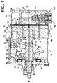
- FIG. 1 there is shown a compressor of swash plate type incorporating a plurality of single-headed pistons each constructed and produced according to one embodiment of this invention.
- reference numeral 10 denotes a cylinder block having a centerline M and a plurality of cylinder bores 12 formed so as to extend in its axial direction such that the cylinder bores 12 are arranged along a circle whose center lies on the centerline M.
- a single-headed piston generally indicated at 14 (hereinafter referred to as “piston 14") is reciprocably received in each of the cylinder bores 12.
- a front housing 16 To one of the axially opposite end faces (the left end face as seen in Fig. 1, witch will be referred to as "front end face") of the cylinder block 10, there is attached a front housing 16.
- front housing 18 To the other end face (the right end face as seen in Fig. 1, which will be referred to as "rear end face"), there is attached a rear housing 18 through a valve plate structure 20.
- the front housing 16, rear housing 18 and cylinder block 10 cooperate to constitute a major portion of the housing assembly of the swash plate type compressor.
- the rear housing 18 and the valve plate structure 20 cooperate to define a suction chamber 22 and a discharge chamber 24, which are connected to a refrigerating circuit (not shown) through an inlet 26 and an outlet 28, respectively.
- the valve plate structure 20 has suction ports 40, suction valves 42, discharge ports 44 and discharge valves 48.
- a rotary drive shaft 50 is disposed in the cylinder block 10 and the front housing 16 such that the axis of rotation of the drive shaft 50 is aligned with the centerline M of the cylinder block 10.
- the drive shaft 50 is supported at its opposite end portions by the front housing 16 and the cylinder block 10 via respective bearings.
- the cylinder block 10 has a central bearing hole 56 in a central portion thereof, and the bearing is disposed in this central bearing hole 56, for supporting the drive shaft 50 at its rear end portion.
- the front end portion of the rotary drive shaft 50 extends through a central portion of the front housing 16, such that the front end of the drive shaft 50 is located outside the front housing 16, so that the drive shaft 50 is connected at its front end to a drive power source (not shown).
- the drive shaft 50 carries a swash plate 60 mounted thereon such that the swash plate 60 is axially movable and tiltable relative to the drive shaft 50.
- the swash plate 60 has a center hole 61 through which the driveshaft 50 extends.
- the diameter of the center hole 61 gradually increases in the opposite axial directions from its axially intermediate portion towards the axially opposite ends.
- To the drive shaft 50 there is fixed a lug plate 62 which is held in engagement with the swash plate 60 through a hinge mechanism 64.
- the lug plate 62 is rotatable with the drive shaft 50 relative to the front housing 16 through a thrust bearing 66.
- the hinge mechanism 64 causes the swash plate 60 to be rotated with the drive shaft 50 during rotation of the drive shaft 50, and permits axial and tilting motions of the swash plate 60.
- the diameter of the center hole 61 at its opposite axial ends is larger than the outside diameter of the drive shaft 50.
- the hinge mechanism 64 includes a pair of support arms 70 fixed to the lug plate 62, and guide pins 74 formed on the swash plate 60.
- the guide pins 74 slidably engage guide holes 72 formed in the support arms 70.
- the piston 14 indicated above includes a neck portion 80 engaging the swash plate 60, a generally cylindrical head portion 82 fitted in the corresponding cylinder bore 12, and a connecting portion 83 connecting the neck portion 80 and the head portion 82.
- the neck portion 80 has a groove 84 formed therein, and the swash plate 60 is held in engagement with the groove 84 through a pair of hemi-spherical shoes 86.
- the hemi-spherical shoes 86 are held in the groove 84 such that the shoes 86 slidably engage the neck portion 80 at their hemi-spherical surfaces, and slidably engage the opposite surfaces of the swash plate 60 at their flat surfaces.
- the head portion 82 cooperates with the cylinder block 10 and the valve plate structure 20 to define a pressurizing chamber 87.
- the configuration of the piston 14 will be described in detail.
- a rotary motion of the swash plate 60 is converted into a reciprocating linear motion of the piston 14 through the shoes 86.
- a refrigerant gas in the suction chamber 22 is sucked or admitted into the pressurizing chamber 87 through the suction port 40 and the suction valve 42, when the piston 14 is moved from its upper dead point to its lower dead point, that is, when the piston 14 is in the suction stroke.
- the refrigerant in the pressurizing chamber 87 is pressurized by the piston 14 when the piston 14 is moved from its lower dead point to its upper dead point, that is, when the piston 14 is in the compression stroke.
- the thus pressurized refrigerant gas is delivered into the discharge chamber 24 through the discharge port 46 and the discharge valve 48.
- a reaction force acts on the piston 14 in the axial direction as a result of compression of the refrigerant gas in the pressurizing chamber 87.
- This compression reaction force is received by the front housing 16 through the piston 14, swash plate 60, lug plate 62 and thrust bearing 66.
- the neck portion 80 of the piston 14 has an integrally formed rotation preventive part 88, which is arranged to contact the inner circumferential surface of the front housing 16, for thereby preventing a rotary motion of the piston 14 about its centerline N (Fig. 1).
- the cylinder block 10 has a supply passage 94 formed therethrough for communication between the discharge chamber 24 and a crank chamber 96 which is defined between the front housing 16 and the cylinder block 10.
- the supply passage 94 is connected to a solenoid-operated control valve 100 provided to control the pressure in the crank chamber 96.
- the solenoid-operated control valve 100 includes a solenoid coil 102, and a shut-off valve 104 which is selectively closed and opened by energization and de-energization of the solenoid coil 120. Namely, the shut-off valve 104 is placed in its closed state when the solenoid coil 102 is energized, and is placed in its open state when the coil 102 is de-energized.
- the rotary drive shaft 50 has a bleeding passage 110 formed therethrough.
- the bleeding passage 110 is open at one of its opposite ends to the central bearing hole 56 indicated above, and is open to the crank chamber 96 through a communication passage 112.
- the central bearing hole 56 communicates at its bottom with the suction chamber 22 through a communication port 114.
- the supply passage 94 is opened, permitting the pressurized refrigerant gas to be delivered from the discharge chamber 24 into the crank chamber 96, resulting in an increase in the pressure in the crank chamber 96, and the angle of inclination of the swash plate 60 is reduced, so that the discharge capacity of the compressor is accordingly reduced.
- the maximum angle of inclination of the swash plate 60 is limited by abutting contact of a stop 120 formed on the swash plate 60, with the lug plate 62, and the minimum angle of inclination of the swash plate 60 is limited by abutting contact of the swash plate 60 with a stop 122 in the form of a ring fixedly fitted on the drive shaft 50.
- the pressure in the crank chamber 96 is controlled by controlling the solenoid-operated control valve 100 to selectively connect and disconnect the crank chamber 96 to and from the discharge chamber 24.
- the angle of inclination of the swash plate 60 is changed with a change in the pressure in the crank chamber 96, so that the stroke of the piston 14 is controlled to control the discharge capacity of the compressor.
- the swash plate type compressor having the piston 14 in each cylinder bore 12 is of a variable capacity type.
- the solenoid coil 102 of the solenoid-operated control valve 100 is controlled by a control device (not shown) depending upon a load acting on the air conditioning system including the present compressor.
- the control device is principally constituted by a computer.
- the cylinder block 10 and each piston 14 are formed of an aluminum alloy.
- the piston 14 is coated at its outer circumferential surface with a fluoro resin film, which prevents a direct contact of the aluminum alloy of the piston 14 with the aluminum alloy of the cylinder block 10, and makes it possible to minimize the amount of clearance between the piston 14 and the cylinder bore 12.
- the cylinder block 10 and the piston 14 may also be formed of a hyper-eutectic aluminum silicon alloy. Other materials may be used for the cylinder block 10 and the piston 14.
- the head portion 82 of the piston 14 includes a body section 126, and an outer sliding section 128 and an inner sliding section 130 which correspond to respective radially outer and inner portions of the cylinder block 10.
- the radially outer portion of the cylinder block 10 is more distant from the centerline M than the radially inner portion of the cylinder block 10.
- the body section 126 has a circular shape in cross section.
- the outer and inner sliding sections 128, 130 extend towards the neck portion 80 from respective circumferential parts of the circular body section 126, which parts correspond to the radially outer and inner portions of the cylinder block 10.
- the outer and inner sliding sections 128, 130 are adapted to slid on the respective circumferential portions of the inner circumferential surface of the cylinder bore 12, which portions correspond to the radially outer and inner portions of the cylinder block 12.
- the connecting portion 83 of the piston 14 consists of a radially outer section 132 connecting the radially outer sliding portion 128 and the neck portion 80, and a radially inner section 134 connecting the radially inner sliding portion 130 and the neck portion 80.
- the piston 14 consists of the head portion 82, neck portion 80 and connecting portion 83, which are formed integrally with each other.
- the neck portion 80 of the piston 14 is a generally U-shaped portion as seen in Fig. 2, which includes a base section 140 having an surface 142, and a pair of side walls in the form of two parallel arm sections 144, 146 which extend from the base section 140 in a direction perpendicular to the centerline N of the piston 14 which passes the center of the cylindrical head portion 82.
- the arm section 144 is located at the end of the neck portion 80 remote from the head portion 82.
- the arm sections 144, 146 have respective inner surfaces 148, 150 which are opposed to each other in the direction of the centerline N and which cooperate with the inner surface 142 of the base section 140 to define the groove 84 indicated above.
- the neck portion 80 has a fillet formed at the boundary between each of the opposed inner surfaces 148, 150 of the arm sections 144, 146 and the inner surface 142 of the base section 140.
- the fillet has a comparatively small radius of curvature, so that the inner surface 142 is smoothly connected at its opposite ends to the opposed inner surfaces 148, 150.
- the inner surfaces 148, 150 have respective part-spherical recesses 152.
- the two part-spherical shoes 86 whose flat surfaces slidably engage the opposite surfaces of the swash plate 60 are held in contact at their part-spherical surfaces with the part-spherical surfaces of the respective part-spherical recesses 152.
- the inner surface 142 of the base section 140 includes a central machined surface area 154 at an intermediate portion thereof as viewed in a direction perpendicular to the centerline N (as viewed in the direction perpendicular to the plane of view of Fig. 2).
- the machined surface area 154 is a generally elongate area (intermediate hatched area shown in Fig. 3) extending in the direction of the centerline N.
- the machined surface area 154 is formed by a machining operation, which will be described.
- the as-cast surface areas 156 are areas formed by die-casting to form a blank 160, which will be described.
- the curved surfaces of the fillets between the inner surface 142 of the base section 140 and the opposed surfaces 148, 150 of the arm sections 144, 146 are also as-cast surface areas.
- the blank 160 consists of a single twin neck portion 166, two connecting portions 168 and two head portions 170, which are formed such that each of the two connecting portions 168 connects the centrally located twin neck portion 166 and the corresponding one of the two head portions 170 located at the opposite ends of the blank 160.
- the twin neck portion 166 consists of two neck portions 164 which are formed in series and integrally with each other and which provide respective two neck portions 80 of the two single-headed pistons 14.
- the two connecting portions 168 provide respective two connecting portions 83 of the two single-headed pistons 14, while the two head portions 170 provide respective two head portions 82 of the two single-beaded pistons 14.
- Each of the two neck portions 164 of the twin neck portion 166 includes a base section 172 having an inner surface 174, a pair of opposed parallel arm sections 178, 180 extending from the opposite ends of the base section 172, and a reinforcing rib 176 which extends between the two arm sections 178, 180 in the longitudinal direction of the blank 160.
- the rib 176 extends also in the direction of extension of the base sections 172, from a central part of the inner surface 174 of the base section 172, which central part is central as seen in the direction perpendicular to the plane of view of Fig. 4.
- the rib 176 connects the inner surface 174 of the base section 172 and inner surfaces 182, 184 of the arm sections 178, 180, in order to reinforce the neck portion 164 for thereby increasing the rigidity and strength of the blank 160.
- the blank 160 is formed of a metallic material, more precisely, an aluminum alloy, by die-casting using a suitable casting mold which consists of two halves.
- the two halves of the mold define a parting plane which includes a centerline of the blank 160 passing the centers of the generally cylindrical head portions 170 and which is parallel to the direction of extension of the arm sections 178, 180 from the base sections 172.
- This process of forming the blank 160 by die-casting is a die-casting step in a method of producing the piston 14.
- a machining step is performed on the die-cast blank 160.
- the machining step includes cutting operations on a plurality of portions of the blank 160, which include the outer circumferential surfaces of the two head portions 170.
- the head portions 170 have respective holding portions 186 extending from their end faces, as shown in Fig. 4.
- the holding portions 186 have respective center holes 188, so that the blank 160 is held at the holding portions 186 by respective chucks while the blank 160 is centered with a pair of centers which engage the respective center holes 188.
- the blank 160 is rotated by a suitable rotary drive device through the chucks.
- the integrally formed blank 160 the rigidity of which is increased by the ribs 176 can be efficiently and accurately machined.
- the machined outer circumferential surfaces of the head portions 170 and other selected surfaces of the blank 160 are coated with a suitable material, such as a film of polytetrafluoroethylene.
- a suitable material such as a film of polytetrafluoroethylene.
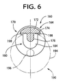
- the twin neck portion 166 is subjected to a machining operation, to remove the ribs 176 of the two neck portions 164, using a cutting tool 190 indicated by two-dot chain lines in Figs. 5 and 6.
- the cutting tool 190 includes a body 194 and a shank 196.
- the body 194 has a peripheral cutting edge formed on its outer circumferential surface, and side cutting edges formed along the peripheries of the opposite side surfaces.
- the cutting tool 190 is rotated by a spindle of a suitable machine tool (e.g., a milling machine), with the shank 196 removably fitted in the bore of the spindle.
- the cutting tool 190 which may be a milling cutter, is capable of performing both a peripheral cutting operation with the peripheral cutting edge and a side cutting operation with the side cutting edges, with the rotating body 194 being moved in the radial direction relative to the rib 176. It will be understood that a difference between the radii of the body 194 and the shank 196 is made slightly larger than the distance of overhang or extension of the arm sections 178, 180 from the inner surface 174 of the base section 172, in order to prevent an interference between the shank 196 and the distal end portions of the arm sections 178, 180, during the cutting operation with the body 194.
- the body 194 is rounded with a suitable radius of curvature at the opposite ends of the peripheral cutting edge so that the peripheral cutting edge is smoothly connected to the side cutting edges through curved cutting edges, as indicated in Fig. 5.
- the fillets are effective to reduce the stress concentration at the boundaries between the inner surface 142 and the inner surfaces 148, 150.
- the stress concentration can be more or less reduced by chamfering the body 194 at the boundaries between the peripheral and side cutting edges.
- the cutting tool 190 is positioned such that the axis of the tool 190 (shank 196) is parallel to the centerline of the head portions 170 and is aligned with the center of the rib 176 as viewed in the direction perpendicular to the plane of view of Fig. 5, namely, in the horizontal direction as seen in Fig. 6. Further, the cutting tool 190 is positioned in its axial direction such that one of the side cutting edges of the body 194 which is remote from the shank 196 is substantially aligned with the inner surface 184 of the arm section 180, as indicated in Fig. 5.
- the cutting tool 190 thus positioned is rotated about its axis and is fed in the radial direction toward the inner surface 174 (i.e., in the direction from the distal ends toward the proximal ends of the arm sections 178, 180).
- the end portion of the rib 176 adjacent to the arm section 180 is removed with the peripheral cutting edge of the body 194, while at the same time the inner surface 184 is machined with the above-indicated one of the side cutting edges.
- the part-spherical recess 152 indicated above is subsequently cut in the machined inner surface 184.
- the cutting tool 190 is retracted in its radial direction away from the inner surface 174 of the base section 172 to the initial position, and is fed in the axial direction until the other side cutting edge of the body 194 which is nearer to the inner surface 182 of the arm section 178 is substantially aligned with the inner surface 182.
- the cutting tool 190 is then fed in the radial direction toward the inner surface 174, to remove the remaining portion of the rib 176 and cut the inner surface 182, in the same manner as described above. In this case, too, a fillet 198 is left between the adjacent ends of the inner surface 174 and the inner surface 182.
- the cutting operation with the cutting tool 190 is performed such that only the rib 176 is removed, without cutting any part of the inner surface 174 on which the rib 176 is not formed on the blank 160 before the cutting operation.
- the inner surface 142 of the base section of the piston 14 produced from the blank 160 has the central machined surface area 154 extending in the direction of the centerline N, and the two as-cast surface areas 156 on the opposite sides of the machined surface area 154, as indicated in Fig. 3 and as described above.
- the as-cast surface areas 154 are provided by chilled layers having comparatively high degrees of hardness and strength, which are obtained by die-casting and which contribute to significant increase in the bending strength and durability of the base section 140 of the piston 14.
- fillets 198 between the adjacent ends of the inner surfaces 174, 182, 184 of the base and arm sections 172, 178, 180 are left uncut so as to provide as-cast surface areas, which contribute to a significant increase in the durability of the neck portion 80 of the piston 14.
- the fillets 198 are located at the portions of the neck portion 80 at which the stress concentration is likely to occur.
- the step of removing the ribs 176 from the blank 160 is followed by a step of forming the part-spherical recesses 152 in the machined inner surfaces 180 and 182 of the arm sections 178, 180, and a step of cutting the blank 160 into two pieces, at a midpoint intermediate between the adjacent arm sections 178 of the two neck portions 164, to thereby provide the two pistons 14.
- the present embodiment of the invention assures improved durability of the piston 14 produced by die-casting, more particularly, a sufficiently high degree of durability of the neck portion 80, although the piston 14 is configured and designed so as to reduce its weight.
- the body 194 of the cutting tool 190 used in the present embodiment has an axial dimension smaller than the dimension of the groove 84 of the piston as measured in the direction parallel to the centerline N, the body 194 may have a dimension equal to the dimension of the groove 84. In this case, the rib 176 may be removed without moving the cutting tool 190 in the axial direction. It is also noted that the body 194 need not have the side cutting edges.
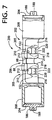
- a blank 200 is used to produce two pieces of a single-headed pistons for a swash plate type compressor, which piston has a single hollow cylindrical head portion.
- the blank 200 consists of a body member 202 and a pair of closure members 204.
- the body member 202 consists of a single twin neck portion 206, and two hollow cylindrical head sections 208 formed integrally with the twin neck portion 206 such that the two hollow cylindrical head sections 208 extend from the opposite ends of the twin neck portion 206.
- the twin neck portion 206 consists of mutually integrally formed two neck portions 205 which provide neck portions of the two pistons.
- each of the neck portions 205 includes a base section 210 and a pair of parallel arm sections 214, 216 extending from an inner surface 212 of the base section 210.
- the arm sections 214, 216 have respective inner surfaces 218, 220 which cooperate with the inner surface of the base section 210 to define a generally U-shaped structure.
- the neck portion 205 further includes a reinforcing rib in the form of a bridge section 222 connecting the opposed inner surfaces 218, 220 of the arm sections 214, 216 such that the bridge section 222 is spaced from the inner surface 212.
- the body member 202 and the closure members 204 are formed by die-casting. In the blank 200 as shown in Fig. 7, the closure members 204 are fixedly fitted in the open end portions of the respective head sections 208, by suitable fixing means such as beam welding.
- the same reference numerals as used in Figs. 1-6 are used to identify the structurally similar or functionally corresponding elements.
- each neck portion 205 of the twin neck portion 206 of the blank 200 is removed by the cutting tool 190, in the same manner as described above with respect to the first embodiment. Then, casting fins formed on the central portion of the inner surface 212 of the base section 210 are removed by the cutting tool 190.
- two mold halves used to die-cast the blank 200 define a parting plane which includes the centerline of the hollow cylindrical head sections 208 and which is parallel to the direction of extension of the arm sections 214, 216.
- small fins are formed in the generally elongate central portion of the inner surface 212 which extends in the direction of the centerline.
- central part of the inner surface 142, 212 of the base section 140, 210 and the fillets 198 are left as-cast in the illustrated embodiments, only the central part of the inner surface 142, 212 may be left as-cast, or any desired portions other than the inner surface 142, 212 and fillets 198 may be left as-cast, in order to increase the strength or wear resistance of those other portions.
- Those other portions may include the outer surface of the base section 140, 210, and the surface of the rotation preventing part 88.
- piston according to the present invention may be configured otherwise.
- the present invention is equally applicable to a double-headed piston having two head portions on the opposite sides of the neck portion.
Landscapes
- Engineering & Computer Science (AREA)
- Mechanical Engineering (AREA)
- General Engineering & Computer Science (AREA)
- Manufacturing & Machinery (AREA)
- Compressors, Vaccum Pumps And Other Relevant Systems (AREA)
- Compressor (AREA)
Abstract
Description
Claims (12)
- A die-cast piston (14) for a swash plate type compressor including a cylinder block (10) having a cylinder bore (12) formed therein, said piston comprising a generally cylindrical head portion (82) slidably movably received in said cylinder bore (12), and a generally U-shaped neck portion (80) having a base section (140) and a pair of substantially parallel arm sections (144, 146) which extend from said base section, said die-cast piston being characterized in that:said base section (140) has an inner surface (142) including at least one as-cast surface area (156) formed in a die-casting process.
- A die-cast piston according to claim 1, wherein said inner surface (142) includes a central machined surface area (154) and a pair of as-cast surface areas (156), said central machined surface area being located at an intermediate portion of said inner surface as viewed in a direction perpendicular to a centerline (N) of the piston which passes a center of said generally cylindrical head portion (82), said central machined surface area being formed as a result of a machining operation in said intermediate portion of said inner surface, and wherein said pair of as-cast surface areas are located on opposite sides of said central machined surface area as viewed in said direction.
- A die-cast piston according to claim 1, wherein a substantially entire portion of said inner surface (142) is an as-cast surface area (212).
- A die-cast piston according to any one of claims 1-3, wherein said pair of arm sections (144, 146) have opposed inner surfaces (148, 150) having as-cast surface areas (198) adjacent to said at least one as-cast surface area (156), said as-cast areas of said arm sections being also formed in said die-casting process.
- A die-cast piston according to any one of claims 1-4, wherein said head portion includes a body section (26) having a circular shape in transverse cross section and cooperating with said cylinder bore (12) to partially define a pressurizing chamber (87), said piston further comprising a connecting portion (83) which connects said head portion and said neck portion (80).
- A die-cast piston according to claim 5, wherein said head portion further includes a sliding section (128, 130) extending from said body section and connecting said body section and said connecting portion.
- A die-cast piston according to claim 1, wherein as-cast surface areas are formed at the boundary between the opposed inner surfaces of the arm sections and the inner surface of the base section.
- A method of producing a die-cast piston (14) for a swash plate type compressor including a cylinder block (10) having a cylinder bore (12) formed therein, said the-cast piston comprising a generally cylindrical head portion (82) slidably movably received in said cylinder bore, and a generally U-shaped neck portion (80) having a base section (140) and a pair of substantially parallel arm sections (144, 146) which extend from said base section, said method comprising the steps of:forming a blank (160, 200) by the casting such that said blank includes: a head portion (170, 208) which gives said head portion (82) of said piston; a neck portion (164, 205) which gives said neck portion (80) of said piston and which includes a base section (172, 210) and a pair of arm sections (178, 180, 214, 216); and a reinforcing portion (176, 222) which extends so as to connect said pair of arm sections of said neck portion of said blank, in a direction parallel to a centerline (N) of said blank which passes a center of said head portion of the blank; andsubjecting said blank to a machining operation to remove said reinforcing portion (176, 222) such that said base section (172, 210) of said neck portion (164, 205) of said blank has an inner surface (174, 212) including at least one as-cast surface area (156) which is left unmachined.
- A method according to claim 8, wherein said reinforcing portion is a rib (176) extending from a central portion of said inner surface (174) of said base section (172) of said blank (160) in a direction of extension of said pair of arm sections (178, 180) of said blank, said central portion being located at an intermediate portion of the inner surface of the base section of said blank as viewed in a direction perpendicular to said centerline (N), said rib connecting said base section and pair of arm sections of said blank, and wherein said step of subjecting said blank to a machining operation comprises removing said rib such that said inner surface (174) of said base section of said blank includes a central machined surface area and a pair of as-cast surface areas located on the opposite sides of said central machined surface area as viewed in the direction perpendicular to said centerline.
- A method according to claim 8, wherein said reinforcing portion is a bridge portion (222) extending to connect said pair of arm sections (214, 216) of said blank (200) in the direction parallel to said centerline, said bridge portion being spaced apart from said inner surface (212) of said base section (210) of said blank, and wherein said central portion is located at an intermediate portion of the inner surface of the base section of said blank as viewed in a direction perpendicular to said centerline (N), and wherein said step of subjecting said blank to a machining operation comprises removing said bridge portion and machining a central portion of said inner surface (212) of said base section of said blank (200) to remove fins formed in said step of forming a blank, such that said inner surface of said base section of aid blank includes a central machined surface area and a pair of as-cast surface areas located on the opposite sides of said central machined surface area as viewed in the direction perpendicular to said centerline.
- A method according to claim 9 or 10, wherein said step of subjecting said blank to a machining operation comprises:positioning a rotary cutting tool (190) having a peripheral cutting edge such that said rotary cutting tool is rotatable about an axis (196) which is parallel to said centerline (N) and which is aligned with a center of said reinforcing portion (176, 222) as viewed in the direction perpendicular to said centerline;feeding said rotary cutting tool in a radial direction thereof toward said inner surface (174, 212) of said base section (172, 210) of said neck portion of said blank (160, 200) while said rotary cutting tool is rotated, so that said reinforcing portion extending between said pair of arm sections of said blank is removed.
- A method according to any one of claims 8-11, wherein said pair of arm sections (178, 180, 214, 216) of said neck portion of said blank have respective opposed inner surfaces (182, 184, 218, 229) which are opposed to each other in the direction parallel to said centerline, and said rotary cutting edge further has side cutting edges formed on opposite sides of said peripheral cutting edge, and wherein said machining operation comprises machining at least a portion of each of said opposed inner surfaces such that an end portion of said each of said opposed inner surfaces which is adjacent to said inner surface of said base section (172, 210) of said blank is left as an as-cast surface area (198).
Applications Claiming Priority (2)
| Application Number | Priority Date | Filing Date | Title |
|---|---|---|---|
| JP23936499A JP2001065452A (en) | 1999-08-26 | 1999-08-26 | Die cast piston and its manufacturing method |
| JP23936499 | 1999-08-26 |
Publications (2)
| Publication Number | Publication Date |
|---|---|
| EP1079109A2 true EP1079109A2 (en) | 2001-02-28 |
| EP1079109A3 EP1079109A3 (en) | 2003-01-02 |
Family
ID=17043675
Family Applications (1)
| Application Number | Title | Priority Date | Filing Date |
|---|---|---|---|
| EP00117379A Withdrawn EP1079109A3 (en) | 1999-08-26 | 2000-08-24 | Hollow cast piston for swash plate compressor |
Country Status (6)
| Country | Link |
|---|---|
| US (1) | US6453554B1 (en) |
| EP (1) | EP1079109A3 (en) |
| JP (1) | JP2001065452A (en) |
| KR (1) | KR100379980B1 (en) |
| CN (1) | CN1286355A (en) |
| BR (1) | BR0003761A (en) |
Cited By (2)
| Publication number | Priority date | Publication date | Assignee | Title |
|---|---|---|---|---|
| WO2003067086A1 (en) * | 2000-08-11 | 2003-08-14 | Kabushiki Kaisha Toyota Jidoshokki | Piston for variable displacement swash plate type compressor and method for manufacturing the same |
| EP2669518A1 (en) * | 2012-05-28 | 2013-12-04 | Valeo Japan Co., Ltd. | Cylinder block for a compressor, in particular swash plate compressor, and swash plate compressor |
Families Citing this family (6)
| Publication number | Priority date | Publication date | Assignee | Title |
|---|---|---|---|---|
| KR100779068B1 (en) * | 2001-08-10 | 2007-11-27 | 한라공조주식회사 | Swash plate compressor |
| JP2003120522A (en) * | 2001-10-10 | 2003-04-23 | Toyota Industries Corp | Piston for fluid machinery, and manufacturing method thereof |
| US6935221B2 (en) | 2003-03-26 | 2005-08-30 | Bristol Compressors, Inc. | Method for manufacturing an aluminum die cast piston for reciprocating compressors |
| JP2017180291A (en) * | 2016-03-30 | 2017-10-05 | 株式会社豊田自動織機 | Double-headed piston swash plate compressor |
| JP2017180292A (en) | 2016-03-30 | 2017-10-05 | 株式会社豊田自動織機 | Double-headed piston swash plate compressor |
| CN108150480A (en) * | 2016-12-05 | 2018-06-12 | 江苏汉力士液压制造有限公司 | Interchangeable steel bushing waves |
Family Cites Families (8)
| Publication number | Priority date | Publication date | Assignee | Title |
|---|---|---|---|---|
| GB437985A (en) * | 1934-08-21 | 1935-11-08 | Joseph Berry | Improvements in and relating to pistons and the manufacture thereof |
| JPS5786580A (en) * | 1980-11-19 | 1982-05-29 | Toyoda Autom Loom Works Ltd | Piston for swash plate type compressor |
| JPH0128311Y2 (en) * | 1980-11-27 | 1989-08-29 | ||
| IT1250214B (en) * | 1991-11-22 | 1995-04-03 | TITANIUM NITRIDE COATING FOR PISTON SHELLS. | |
| JP3631344B2 (en) | 1995-11-24 | 2005-03-23 | カルソニックカンセイ株式会社 | Swash plate compressor |
| JP3695724B2 (en) * | 1996-03-19 | 2005-09-14 | カルソニックカンセイ株式会社 | Manufacturing method of single-headed piston of swash plate compressor |
| JP3880158B2 (en) * | 1997-10-21 | 2007-02-14 | カルソニックカンセイ株式会社 | Swash plate compressor |
| JPH11193780A (en) * | 1997-12-26 | 1999-07-21 | Toyota Autom Loom Works Ltd | Single-headed piston swash plate type compression machine and method for manufacturing swash plate |
-
1999
- 1999-08-26 JP JP23936499A patent/JP2001065452A/en active Pending
-
2000
- 2000-05-17 KR KR10-2000-0026300A patent/KR100379980B1/en not_active Expired - Fee Related
- 2000-08-23 BR BR0003761-3A patent/BR0003761A/en not_active Application Discontinuation
- 2000-08-24 US US09/645,000 patent/US6453554B1/en not_active Expired - Fee Related
- 2000-08-24 EP EP00117379A patent/EP1079109A3/en not_active Withdrawn
- 2000-08-28 CN CN00126070A patent/CN1286355A/en active Pending
Cited By (4)
| Publication number | Priority date | Publication date | Assignee | Title |
|---|---|---|---|---|
| WO2003067086A1 (en) * | 2000-08-11 | 2003-08-14 | Kabushiki Kaisha Toyota Jidoshokki | Piston for variable displacement swash plate type compressor and method for manufacturing the same |
| EP2669518A1 (en) * | 2012-05-28 | 2013-12-04 | Valeo Japan Co., Ltd. | Cylinder block for a compressor, in particular swash plate compressor, and swash plate compressor |
| WO2013179642A1 (en) * | 2012-05-28 | 2013-12-05 | Valeo Japan Co., Ltd. | Cylinder block for a compressor, in particular swash plate compressor, and swash plate compressor |
| US10047733B2 (en) | 2012-05-28 | 2018-08-14 | Valeo Japan Co., Ltd. | Cylinder block for a compressor, in particular swash plate compressor, and swash plate compressor |
Also Published As
| Publication number | Publication date |
|---|---|
| BR0003761A (en) | 2001-04-03 |
| US6453554B1 (en) | 2002-09-24 |
| JP2001065452A (en) | 2001-03-16 |
| EP1079109A3 (en) | 2003-01-02 |
| CN1286355A (en) | 2001-03-07 |
| KR20010020848A (en) | 2001-03-15 |
| KR100379980B1 (en) | 2003-04-14 |
Similar Documents
| Publication | Publication Date | Title |
|---|---|---|
| EP1134412B1 (en) | Method and apparatus for producing hollow piston for compressor by forging | |
| JP3695724B2 (en) | Manufacturing method of single-headed piston of swash plate compressor | |
| US6453554B1 (en) | Swash plate type compressor piston wherein inner surface of base section of neck portion has as-cast surface area | |
| US6675475B2 (en) | Method of producing shoe for swash plate type compressor | |
| US6453555B1 (en) | Method of producing compressor piston | |
| US20020170425A1 (en) | Shoe for swash plate type compressor and method of producing the same | |
| US20030088979A1 (en) | Method of producing aluminum ball, method of producing compressor shoe, and compressor shoe produced by the method | |
| EP1253318B1 (en) | Swash plate type compressor and shoe for the same | |
| US6412171B1 (en) | Swash plate type compressor piston wherein inner bottom surface of hollow head section has 3-dimensional configuration nonaxisymmetric with respect to its centerline | |
| KR100391004B1 (en) | Method of producing a swash plate type compressor piston whose head portion is formed by pore-free die-casting | |
| JP3937690B2 (en) | Compressor | |
| JP2002307156A (en) | Die casting method and die unit | |
| US20020092151A1 (en) | Cast spherical crown shoe of compressor | |
| US6378416B1 (en) | Swash plate type compressor piston wherein inner surface of hollow cylindrical section of body portion has axially extending reinforcing projections | |
| EP1079108A2 (en) | Method of forming hollow head portion of piston for swash plate type compressor | |
| JP2001107853A (en) | Method of making for pistion for swash plate type compressor | |
| EP1126167A2 (en) | Method of producing swash plate type compressor piston | |
| JP2001328032A (en) | Method of making piston for swash plate type compressor | |
| JP2002054565A (en) | Piston for variable displacement type swash plate compressor and method of manufacturing the piston | |
| JP2001263240A (en) | Method of manufacturing hollow piston for compressor | |
| JP2001342955A (en) | Chip intrusion preventing method for compressor piston | |
| JP2005042596A (en) | Swash plate of swash plate compressor, and working method for the swash plate | |
| JPH03253774A (en) | Axial plunger pump |
Legal Events
| Date | Code | Title | Description |
|---|---|---|---|
| PUAI | Public reference made under article 153(3) epc to a published international application that has entered the european phase |
Free format text: ORIGINAL CODE: 0009012 |
|
| 17P | Request for examination filed |
Effective date: 20000824 |
|
| AK | Designated contracting states |
Kind code of ref document: A2 Designated state(s): AT BE CH CY DE DK ES FI FR GB GR IE IT LI LU MC NL PT SE |
|
| AX | Request for extension of the european patent |
Free format text: AL;LT;LV;MK;RO;SI |
|
| RAP1 | Party data changed (applicant data changed or rights of an application transferred) |
Owner name: KABUSHIKI KAISHA TOYOTA JIDOSHOKKI |
|
| PUAL | Search report despatched |
Free format text: ORIGINAL CODE: 0009013 |
|
| AK | Designated contracting states |
Kind code of ref document: A3 Designated state(s): AT BE CH CY DE DK ES FI FR GB GR IE IT LI LU MC NL PT SE |
|
| AX | Request for extension of the european patent |
Free format text: AL;LT;LV;MK;RO;SI |
|
| AKX | Designation fees paid |
Designated state(s): DE FR IT |
|
| 17Q | First examination report despatched |
Effective date: 20040618 |
|
| STAA | Information on the status of an ep patent application or granted ep patent |
Free format text: STATUS: THE APPLICATION HAS BEEN WITHDRAWN |
|
| 18W | Application withdrawn |
Effective date: 20050504 |