EP1079078A2 - Variable valve apparatus of internal combustion engine and method of varying the open-close characteristic of an engine valve - Google Patents
Variable valve apparatus of internal combustion engine and method of varying the open-close characteristic of an engine valve Download PDFInfo
- Publication number
- EP1079078A2 EP1079078A2 EP00118075A EP00118075A EP1079078A2 EP 1079078 A2 EP1079078 A2 EP 1079078A2 EP 00118075 A EP00118075 A EP 00118075A EP 00118075 A EP00118075 A EP 00118075A EP 1079078 A2 EP1079078 A2 EP 1079078A2
- Authority
- EP
- European Patent Office
- Prior art keywords
- camshaft
- axis
- movement
- internal combustion
- combustion engine
- Prior art date
- Legal status (The legal status is an assumption and is not a legal conclusion. Google has not performed a legal analysis and makes no representation as to the accuracy of the status listed.)
- Withdrawn
Links
Images


Classifications
-
- F—MECHANICAL ENGINEERING; LIGHTING; HEATING; WEAPONS; BLASTING
- F01—MACHINES OR ENGINES IN GENERAL; ENGINE PLANTS IN GENERAL; STEAM ENGINES
- F01L—CYCLICALLY OPERATING VALVES FOR MACHINES OR ENGINES
- F01L1/00—Valve-gear or valve arrangements, e.g. lift-valve gear
- F01L1/34—Valve-gear or valve arrangements, e.g. lift-valve gear characterised by the provision of means for changing the timing of the valves without changing the duration of opening and without affecting the magnitude of the valve lift
- F01L1/344—Valve-gear or valve arrangements, e.g. lift-valve gear characterised by the provision of means for changing the timing of the valves without changing the duration of opening and without affecting the magnitude of the valve lift changing the angular relationship between crankshaft and camshaft, e.g. using helicoidal gear
-
- F—MECHANICAL ENGINEERING; LIGHTING; HEATING; WEAPONS; BLASTING
- F01—MACHINES OR ENGINES IN GENERAL; ENGINE PLANTS IN GENERAL; STEAM ENGINES
- F01L—CYCLICALLY OPERATING VALVES FOR MACHINES OR ENGINES
- F01L1/00—Valve-gear or valve arrangements, e.g. lift-valve gear
- F01L1/46—Component parts, details, or accessories, not provided for in preceding subgroups
-
- F—MECHANICAL ENGINEERING; LIGHTING; HEATING; WEAPONS; BLASTING
- F01—MACHINES OR ENGINES IN GENERAL; ENGINE PLANTS IN GENERAL; STEAM ENGINES
- F01L—CYCLICALLY OPERATING VALVES FOR MACHINES OR ENGINES
- F01L13/00—Modifications of valve-gear to facilitate reversing, braking, starting, changing compression ratio, or other specific operations
- F01L13/0015—Modifications of valve-gear to facilitate reversing, braking, starting, changing compression ratio, or other specific operations for optimising engine performances by modifying valve lift according to various working parameters, e.g. rotational speed, load, torque
- F01L13/0036—Modifications of valve-gear to facilitate reversing, braking, starting, changing compression ratio, or other specific operations for optimising engine performances by modifying valve lift according to various working parameters, e.g. rotational speed, load, torque the valves being driven by two or more cams with different shape, size or timing or a single cam profiled in axial and radial direction
- F01L13/0042—Modifications of valve-gear to facilitate reversing, braking, starting, changing compression ratio, or other specific operations for optimising engine performances by modifying valve lift according to various working parameters, e.g. rotational speed, load, torque the valves being driven by two or more cams with different shape, size or timing or a single cam profiled in axial and radial direction with cams being profiled in axial and radial direction
Definitions
- the invention relates to a variable valve apparatus of an internal combustion engine that varies the open-close characteristic of an engine valve by moving a three-dimensional cam in the direction of an axis of the cam, the cam having a cam profile that continuously changes in the direction of the cam axis and a method of varying the open-close characteristic of an engine valve.
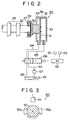
- FIGURES 5A and 5B A construction of a detection portion provided in the apparatus for detecting the amount of movement of the camshaft in a direction of an axis thereof is illustrated in FIGURES 5A and 5B.
- FIGURE 5A is a view of the detection portion taken in a direction of the axis of the camshaft.
- FIGURE 5B is a side view of the detection portion taken in a direction indicated by an arrow B in FIGURE 5A.
- an engine camshaft 22 provided with a three-dimensional cam has a pair of detected portions 74 for reference extending linearly in the direction of the axis of the camshaft 22, and a movement amount detected portion 75 for amount of movement extending helically in the direction of the axis.
- An electromagnetic pickup 76 that generates pulses corresponding to passage of the detected portions 74, 75 is secured to a body of the engine (cylinder head) in the vicinity of the camshaft 22.
- camshaft reference position is set as a positioning reference in the direction of the axis of a camshaft for mounting the camshaft to a cylinder head, or as a detection reference for detecting the amount of movement of the camshaft during operation.
- This camshaft reference position is also referred to when the electromagnetic pickup 76 and other members are secured to predetermined positions on the cylinder head.
- a base member (cylinder head) to which the electromagnetic pickup 76 is secured and the camshaft where the movement amount detected portion 75 and the like are provided are made of different materials; for example, the cylinder head is formed as a cast aluminum alloy and the camshaft is formed from iron, an increase in the engine temperature causes, in some cases, a positional deviation due to the different rates of thermal expansion of the materials. In such a case, the precision in detecting the amount of movement of the camshaft may decrease, and the control precision related to the valve characteristics determined by the three-dimensional cam, such as the valve-opening angle and the valve lift, may also decrease.
- the position of the electromagnetic pickup 76 and the positions of the reference detected portions 74 and the movement amount detected portion 75 are initially adjusted (initialized) based on the camshaft reference position, and the reference position regarding the detection of the amount of movement of the camshaft is initialized, it is difficult to prevent the initialized positions from deviating with increases in the engine temperature, due to different rates of thermal expansion. If detection related to the amount of movement of the camshaft is performed while such a positional deviation exists, there is a possibility that precise control of the valve characteristics through the use of the three-dimensional cam becomes difficult. This possibility is particularly great if the deviation is great.
- variable valve apparatus of an internal combustion engine is capable of realizing more precise valve characteristic control by reducing the error in detection of the amount of movement of a camshaft caused by a difference in the rate of thermal expansion.
- variable valve apparatus of an internal combustion engine for varying an open-close characteristic of an engine valve includes a camshaft that has a plurality of three-dimensional cams whose cam profile continuously changes in a direction of a cam axis and that is supported so as to be rotatable and slidable in the direction of the cam axis relative to a body of the internal combustion engine.
- the apparatus also includes a movement mechanism that moves the camshaft in a direction of an axis of the camshaft, a camshaft position marker provided in the camshaft, and a camshaft movement amount detector that is provided in the body of the internal combustion engine and that detects the camshaft position marker and detects an amount of movement of the camshaft in the direction of the axis of the camshaft.
- the camshaft position marker and the camshaft movement amount detector are provided near a reference position that is provided at a predetermined position in a direction of a length of the camshaft.
- variable valve apparatus is able to reduce the error in detection of the amount of movement of the camshaft caused by the different rates of thermal expansion.
- the reference position may be provided near a central portion of the camshaft.
- camshaft movement amount detector near a central portion of the camshaft reduces the distance from the movement amount detector to a farthest three-dimensional cam. Therefore, it becomes possible to reduce the deviation from the initialized position of the movement amount detection means, the deviation being caused by thermal expansion of the camshaft, and to reduce the variation in the amounts of control achieved by the three-dimensional cams in the valve characteristic control.
- variable valve apparatus Various exemplary embodiments of the variable valve apparatus according to the invention will be described hereinafter with reference to the accompanying drawings.
- FIGURE 1 is a partial sectional side view of a construction of a first embodiment of the invention.
- a variable valve apparatus of the embodiment includes a camshaft 22 provided with three-dimensional cams 25 and a spline gear 26, a hydraulic actuator 30 for moving the camshaft 22 in the directions of the camshaft axis, and a movement amount detection portion 50 for detecting the amount of movement of the camshaft 22.
- the camshaft 22 is supported by a bearing portion of a cylinder head 6 that forms an internal combustion engine body, in such a manner that the camshaft 22 is rotatable and movable in the directions of the axis of the camshaft 22.
- the camshaft 22 is rotated by an output shaft (not shown) of the engine.
- the cam profile of each three-dimensional cam 25 continuously changes in a direction of the camshaft axis from a cam profile that provides a large valve lift (or a large valve-opening angle) and that is suitable to high-speed/high-load operation of the engine to a cam profile that provides a small valve lift (or a small valve-opening angle) and that is suitable to low-speed/low-load operation (see FIGURE 1).
- each three-dimensional cam 25 is shaped so that the amount of valve lift increases at the side of the hydraulic actuator 30 and decreases at the side of the spline gear 26. Therefore, the camshaft 22 is constantly urged in the direction indicated by arrow F2 away from the hydraulic actuator 30 toward the spline gear 26 by forces from valve springs 41 of engine valves 40 (only one engine valve is shown in FIGURE 1 for clarity) that are pressed by the three-dimensional cams 25.
- the engine valves 40 are driven in the opening and closing directions based on pressurization by the three-dimensional cams 25.
- the camshaft 22 is slid in a direction of the camshaft axis, the cam profile of a portion of each three-dimensional cam 25 that contacts the corresponding engine valve 40 changes. Therefore, the valve characteristics of the engine valves 40, such as the valve lift and the valve-opening angle can be varied.
- the spline gear 26 is bolted to a distal end of the camshaft 22. Due to the spline gear 26, the camshaft 22 can be rotated together with a sprocket 11 even when the camshaft 22 is slid in a direction of the camshaft axis. More specifically, the spline gear 26 is movable, that is, the camshaft 22 is movable, in the directions of the axis of the camshaft 22, along splines 12 formed in an inner peripheral surface of the sprocket 11.
- the sprocket 11 has, on its outer peripheral surface, outer teeth 11a that are engaged with a timing chain (not shown).
- the chain transmits torque from a crankshaft (not shown) to the sprocket 11 and the camshaft 22.
- the sprocket his provided with a cover 13 that is a member for restricting movement of the camshaft 22 in a direction indicated by the arrow F2 in FIGURE 1.
- a base end portion of the camshaft 22 (the right-side end portion in FIGURE 1) is bolted to an inner ring of a bearing 27.
- An outer ring of the bearing 27 is secured to a rod 32 by a nut 28.
- the hydraulic actuator 30 is disposed at the distal end portion of the camshaft 22 as shown in FIGURES 1 and 2.
- the hydraulic actuator 30 is provided for moving the camshaft 22 in the directions of the camshaft axis via the rod 32.
- the hydraulic actuator 30 includes a piston 31 and a case 33 secured to the cylinder head 6.
- the rod 32 is secured at one end to the piston 31.
- the case 33 defines therein a cylindrically shaped cylinder 36.
- the piston 31 is housed in the cylinder 36 in such a manner that the piston 31 is slidable in the directions of the camshaft axis.
- the piston 31, the rod 32 and the camshaft 22 are slidable together as one piece in the directions of the camshaft axis.
- the internal space of the cylinder 36 is divided into two hydraulic chambers 34, 35 by the piston 31.
- Operating fluid is charged into the hydraulic chambers 34, 35 to actuate the hydraulic actuator 30. Used as the operating fluid may be a portion of lubricating fluid for various portions of the engine.
- Fluid passages 64, 65 are connected to the hydraulic chambers 34, 35, respectively, to supply the operating fluid to and discharge it from the hydraulic chambers 34, 35.
- the fluid passages 64, 65 are connected at other ends thereof to a fluid pressure control valve 66 as shown in FIGURE 2.
- the fluid pressure control valve 66 is an electromagnetic direction changeover valve that is duty-controlled by an electronic control unit (ECU) 55.
- ECU electronice control unit
- two fluid passages 62, 63 are connected to the fluid pressure control valve 66.
- the fluid passage 62 has in its partway a pump 67 that pumps the operating fluid from a pan 61 storing the operating fluid and that pressurizes and ejects the operating fluid. That is, the fluid passage 62 is a passage for supplying the operating fluid to the fluid pressure control valve 66.
- the fluid passage 63 is a passage for discharging the operating fluid into the oil 61.
- the fluid passages 62-65 may be formed in the cylinder head 6 or a cylinder block (not shown) that form the engine body.
- the fluid pressure control valve 66 is controlled so as to selectively establish communication between the fluid passages 64, 65 connected to the hydraulic chambers 34, 35 of the hydraulic actuator 30 and the operating fluid supplying passage 62 and the operating fluid discharging passage 63 (two combinations) or to block the communication (balancing state).
- the fluid pressure control valve 66 is in either one of the communicating states, the operating fluid is supplied from the pump 67 to one of the hydraulic chambers 34, 35, and is discharged from the other one of the hydraulic chambers 34, 35 to the pan 61.
- the fluid pressure control valve 66 is in the blocking (balancing) state, the pressure of the operating fluid in the hydraulic chambers 34, 35 is maintained.
- the fluid pressure control valve 66 adjusts the pressure of the operating fluid in the hydraulic chambers 34, 35 by controlling the amounts of the operating fluid supplied and discharged.
- the hydraulic actuator 30 operates based on the control of the pressure of the operating fluid in the hydraulic chambers 34, 35. For example, if the operating fluid pressure in the hydraulic chamber 34 is made higher than the pressure in the hydraulic chamber 35, the piston 31 receives a force based on the operating fluid pressure difference across the piston 31 such that the piston 31 moves together with the rod 32 and the camshaft 22 in a direction indicated by the arrow F1 in FIGURE 1. As a result, the cam profile of a portion of each three-dimensional cam 25 that contacts the corresponding engine valve 40 changes to a cam profile that provides an increased valve lift (or an increased valve-opening angle).
- the camshaft 22 has a detected portion 52 that is used to detect the amount of movement of the camshaft 22 in the directions of the camshaft axis, at a position between the distal end (left-side end in FIGURE 1) of the camshaft 22 and the three-dimensional cam 25 that is disposed nearest to the distal end among all the three-dimensional cam 25.
- the detected portion 52 is provided with a pair of protruded movement amount detected portions 52a for the amount of movement (see FIGURE 3).
- the movement amount detected portions 52a are made of a magnetic material.
- the movement amount detected portions 52a extend helically in the directions of the axis of the camshaft 22.
- a camshaft position sensor 51 formed by an electromagnetic pickup is provided at such a position on the engine body, for example, on the cylinder head 6, that the camshaft position sensor 51 faces the detected portion 52.
- pulse signals (currents) induced in the camshaft position sensor 51 when the movement amount detected portions 52a pass by the sensor 51 during rotation of the camshaft 22 shift in phase relative to an output signal (reference pulse signal) from, for example, a crank angle sensor provided on a crankshaft that is an output shaft of the engine, by a shift amount corresponding to the amount of movement of the camshaft 22 in the direction of the camshaft axis. Therefore, by monitoring the phase difference between the pulse signals, the amount of movement of the camshaft 22 can be detected at any time.
- the operational condition of the engine is detected from output signals of various sensors 53 (FIGURE 2), such as the crank angle sensor, a pressure sensor for detecting the pressure of intake air introduced into the engine, etc., and, on the basis of the operational condition, calculates a target position of the camshaft 22 in the direction of the camshaft axis at which a suitable valve characteristic will be obtained. Furthermore, the apparatus detects the actual position of the camshaft 22 in the direction of the camshaft axis by referring to the output signal of the camshaft position sensor 51 as well. Then, based on comparison between the target position and the actual position of the camshaft 22 in the direction of the camshaft axis, the ECU 55 feedback-controls the fluid pressure control valve 66.
- various sensors 53 such as the crank angle sensor, a pressure sensor for detecting the pressure of intake air introduced into the engine, etc.
- variable valve apparatus secures a positional precision by setting a position where the spline gear 26 disposed at the distal end of the camshaft 22 contacts the cover 13 of the sprocket 11, as a reference position P0 of the camshaft 22 in the direction of the camshaft axis.
- the initial positioning (initialization) of the camshaft position sensor 51 and the detected portion 52 that is, the initialization of the detection reference position Ps for detecting the amount of movement of the camshaft 22 in the direction of the cam axis, is performed based on the reference position P0 of the camshaft 22.
- the detection reference position Ps is initialized based on the reference position P0, a positional deviation can occur.
- the cylinder head 6 and the camshaft 22 are formed from different materials, for example, if the cylinder head 6 is formed as a cast aluminum alloy and the camshaft 22 is formed from iron, the relative positional relationship between the camshaft position sensor 51 and the detected portion 52 changes with increases in the temperature of the engine, due to the different thermal expansion rates of the materials (e.g., aluminum has a greater linear expansion rate than iron). Thus, a deviation ⁇ Ps occurs to the initialized detection reference position Ps.
- the camshaft movement amount detection portion 50 having the camshaft position sensor 51 and the detected portion 52, is provided near the reference position P0 of the camshaft 22, so that the deviation ⁇ Ps of the detection reference position Ps caused by different rates of thermal expansion as mentioned above is minimized. More specifically, with reference to the reference position P0, the positional deviation caused by the different thermal expansion rates of the cylinder head 6 and the camshaft 22 increases with increases in distance from the reference position P0. Therefore, the provision of the camshaft movement amount detection portion 50 near the reference position P0 minimizes the effect of the deviation caused by thermal expansion.
- variable valve apparatus of the embodiment shown in Fig. 1 minimizes the error deviation ⁇ Ps of the detection reference position Ps caused by the difference in thermal expansion between the cylinder head 6 and the camshaft 22 since the camshaft movement amount detection portion 50 is provided near the reference position P0 of the camshaft 22. Therefore, the apparatus is able to perform precise valve characteristic control with a minimized error in detection of the amount of movement of the camshaft.
- the reference position P0 of the camshaft 22 is set on the contact surface of the cover 13 that contacts the spline gear 26, that is, at a position at which the camshaft 22 is restricted from moving in the direction of the arrow F2 in FIGURE 2, it should be appreciated that the reference position P0 may be set at a position where the camshaft 22 is restricted from moving in the direction of the arrow F1 in FIGURE 1, as indicated by P0' in FIGURE 1.
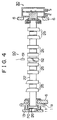
- variable valve apparatus of the invention A second embodiment of the variable valve apparatus of the invention will be described with reference to FIGURE 4.
- variable valve apparatus of the second embodiment differs from the variable valve apparatus of the first embodiment shown in FIGURE 1 in the position of the camshaft movement amount detection portion 50. More specifically, in the variable valve apparatus of the second embodiment shown in FIGURE 4, a detected portion 52 forming the camshaft movement amount detection portion 50 is provided in a central portion of the camshaft 22. A camshaft position sensor 51 is secured to a predetermined position (not shown) on a cylinder head 6 so as to face the detected portion 52.
- the provision of the camshaft movement amount detection portion 50 in a central portion of the camshaft 22 reduces the distance from the detection portion 50 to a three-dimensional cam 25 that is farthest from the detection portion 50, that is, the greatest one of the distances to the three-dimensional cams 25. Therefore, even though the camshaft 22 thermally expands due to increases of in the temperature of the engine, variations in the amounts of control of the valve characteristics achieved by the three-dimensional cams 25 can be reduced. More specifically, when the camshaft 22 thermally expands as described above, the error of the detected value of the amount of movement of the camshaft 22 from the actual position of a three-dimensional cam 25 becomes greater if the cam 25 is farther from the camshaft movement amount detection portion 50.
- the camshaft movement amount detection portion 50 is provided in a central portion of the camshaft 22, the distance from the detection portion 50 to a farthest three-dimensional cam is reduced, for example, to about half the distance to a farthest three-dimensional cam in the case where a camshaft movement amount detection portion 50 is provided at an end of the camshaft 22.
- the effect of thermal expansion of the camshaft 22 is significantly reduced in this embodiment.
- the reference position of the camshaft 22 may also be set near the camshaft movement amount detection portion 50, that is, near a central portion of the camshaft 22. In that case, it becomes possible to reduce both the deviation from the initialized position of the movement amount detection means caused by thermal expansion of the camshaft and the variation in the amounts of control achieved by the three-dimensional cams 25 in the valve characteristic control.
- the actuator for moving the camshaft 22 in the directions of the axis thereof is not limited to the hydraulic actuator 30 operated based on hydraulic pressure, but may also be a different type of actuator, for example, a mechanical or a pneumatic actuator.
- the camshaft movement amount detection portion 50 is not limited to a detection portion that includes a camshaft position sensor 51 formed by an electromagnetic pickup and a detected portion 52 having a pair of protruded movement amount detected portions 52a extending helically in the directions of the cam axis.
- the camshaft position sensor may be formed by a photo-sensor or a distance sensor.
- the detected portion may have only one movement amount detected portion that is protruded and helically extends.
- a variable valve apparatus of an internal combustion engine is capable of realizing more precise valve characteristic control by reducing the error in detection of the amount of movement of a camshaft caused by a difference in the rate of thermal expansion.
- the variable valve apparatus has a camshaft that is supported so as to be rotatable and slidable in a direction of an axis thereof and that has three-dimensional cams whose cam profile continuously changes in the direction of the axis.
- the apparatus also has an actuator for moving the camshaft in the direction of its axis.
- the apparatus further has a camshaft position sensor provided in a cylinder head, a detected portion provided in the camshaft, and a camshaft movement amount detection portion for detecting the amount of movement of the camshaft in the direction of the axis.
- the camshaft movement amount detection portion is provided near a camshaft reference position.
Landscapes
- Engineering & Computer Science (AREA)
- Mechanical Engineering (AREA)
- General Engineering & Computer Science (AREA)
- Valve Device For Special Equipments (AREA)
- Output Control And Ontrol Of Special Type Engine (AREA)
- Combined Controls Of Internal Combustion Engines (AREA)
- Fluid-Driven Valves (AREA)
Abstract
Description
Claims (6)
- A variable valve apparatus of an internal combustion engine comprising: a camshaft (22) that has a plurality of three-dimensional cams (25) whose cam profile continuously changes in a direction of a cam axis and that is supported so as to be rotatable and slidable in the direction of the camshaft axis relative to a body of the internal combustion engine; movement means (30) for moving the camshaft in a direction of a camshaft axis; and camshaft movement amount detection means (50) for detecting an amount of movement of the camshaft (22) in the direction of the camshaft axis, the means (50) including a detection portion (51) provided in the body of the internal combustion engine and a detected portion (52) provided in the camshaft, the variable valve apparatus being characterized in that the camshaft movement amount detection means (50) is provided near a reference position that is provided in the direction of the axis of the camshaft (22).
- A variable valve apparatus of an internal combustion engine according to claim 1, characterized by further comprising a movement restriction member (13) that is provided at a side of a surface of one end of two ends of the camshaft (22) where the movement means (30) is not provided and that restricts a moving distance of the camshaft in the direction of the camshaft axis,
wherein the reference position is a position at which the surface of the one end contacts the movement restriction member (13). - A variable valve apparatus of an internal combustion engine according to claim 1, characterized in that the reference position is a central portion of the camshaft (22).
- A method of varying the open-close characteristic of an engine valve of a variable valve apparatus of an internal combustion engine having a camshaft (22) that has a plurality of three-dimensional cams (25) whose cam profile continuously changes in a direction of a camshaft axis and that is supported so as to be rotatable and slidable in the direction of the camshaft axis relative to a body of the internal combustion engine; a camshaft position marker provided in the camshaft; and a camshaft movement amount detecting means (50) that is provided in the body of the internal combustion engine, wherein the camshaft position marker and the camshaft movement amount detecting means (50) are provided near a reference position that is provided at a predetermined position in the direction of the camshaft axis; the method characterized by comprising:moving the camshaft (22) in the direction of the of the camshaft axis; anddetecting the camshaft position marker and an amount of movement of the camshaft in the direction of the camshaft axis.
- A method according to claim 4, characterized by further comprising:providing a restriction member (13) at a side of an end portion of the camshaft and that restricts a movement of the camshaft in the direction of the camshaft axis, wherein the reference position is a position at which the camshaft (22) contacts the restriction member (13).
- A method according to claim 4, wherein the reference position is near a central portion of the camshaft (22).
Applications Claiming Priority (2)
| Application Number | Priority Date | Filing Date | Title |
|---|---|---|---|
| JP23751199A JP2001065371A (en) | 1999-08-24 | 1999-08-24 | Variable valve train for internal combustion engine |
| JP23751199 | 1999-08-24 |
Publications (2)
| Publication Number | Publication Date |
|---|---|
| EP1079078A2 true EP1079078A2 (en) | 2001-02-28 |
| EP1079078A3 EP1079078A3 (en) | 2002-12-04 |
Family
ID=17016416
Family Applications (1)
| Application Number | Title | Priority Date | Filing Date |
|---|---|---|---|
| EP00118075A Withdrawn EP1079078A3 (en) | 1999-08-24 | 2000-08-23 | Variable valve apparatus of internal combustion engine and method of varying the open-close characteristic of an engine valve |
Country Status (3)
| Country | Link |
|---|---|
| US (1) | US6415753B1 (en) |
| EP (1) | EP1079078A3 (en) |
| JP (1) | JP2001065371A (en) |
Cited By (7)
| Publication number | Priority date | Publication date | Assignee | Title |
|---|---|---|---|---|
| EP1403513A1 (en) * | 2002-09-27 | 2004-03-31 | Honda Giken Kogyo Kabushiki Kaisha | Engine rotation angle detection device arrangement configuration |
| FR2855845A1 (en) * | 2003-06-03 | 2004-12-10 | Suzuki Motor Co | CONTROL DEVICE AND CONTROL SOFTWARE FOR A HEAT ENGINE |
| DE102007003966A1 (en) | 2007-01-26 | 2008-07-31 | Schaeffler Kg | Raumnockentrieb with an improved balance of the valve lift |
| WO2009062587A1 (en) * | 2007-11-17 | 2009-05-22 | Daimler Ag | Valve driving device |
| EP2276330A2 (en) | 2009-07-16 | 2011-01-19 | Kunststoff Schwanden AG | Housing wall for fixing a device to a machine |
| EP2325444A4 (en) * | 2008-08-13 | 2012-01-11 | Chery Automobile Co Ltd | A hydraulic camshaft and a hydraulic controlling system thereof |
| CN103174486A (en) * | 2011-12-21 | 2013-06-26 | Dr.Ing.h.c.F.保时捷股份公司 | Valve drive device for internal combustion engine |
Families Citing this family (15)
| Publication number | Priority date | Publication date | Assignee | Title |
|---|---|---|---|---|
| SE522629C2 (en) * | 2000-06-05 | 2004-02-24 | Volvo Lastvagnar Ab | Apparatus for controlling the phase angle between a first and a second crankshaft |
| US6488008B1 (en) * | 2001-05-31 | 2002-12-03 | Ford Global Technologies, Inc. | Method and system for determining the variable cam timing rate-of-change in an engine |
| EP1302645A3 (en) * | 2001-10-12 | 2004-09-29 | Hitachi Unisia Automotive Ltd. | Apparatus and method for controlling the intake air amount of an internal combustion engine |
| US6536389B1 (en) * | 2002-04-16 | 2003-03-25 | Ford Global Technologies, Inc. | Adaptive control of cylinder valve timing in internal combustion engine |
| KR100666774B1 (en) * | 2004-12-17 | 2007-01-09 | 현대자동차주식회사 | Cam drive system for variable control of automobiles |
| DE102006049243A1 (en) * | 2006-10-18 | 2008-04-24 | Mahle International Gmbh | Actuator for two parallel rotating camshafts |
| ES2323400B1 (en) * | 2007-08-08 | 2010-04-30 | Antonio Ribas Bonet | CAMSHAFT. |
| US7546827B1 (en) | 2008-08-21 | 2009-06-16 | Ford Global Technologie, Llc | Methods for variable displacement engine diagnostics |
| JP2011102566A (en) * | 2009-11-11 | 2011-05-26 | Suzuki Motor Corp | Valve system and internal combustion engine therewith |
| JP5616700B2 (en) * | 2010-06-25 | 2014-10-29 | パナソニック株式会社 | Sensor device |
| CN102182529A (en) * | 2011-05-24 | 2011-09-14 | 奇瑞汽车股份有限公司 | Variable lift camshaft |
| US9605603B2 (en) * | 2013-04-05 | 2017-03-28 | Ford Global Technologies, Llc | Position detection for lobe switching camshaft system |
| CN103711539B (en) * | 2014-01-13 | 2016-04-06 | 浙江大学 | A kind ofly can open to engine valve the assembly that the duration changes |
| US11352913B2 (en) * | 2017-12-20 | 2022-06-07 | Guangzhou Automobile Group Co., Ltd. | Variable valve lift device and automobile |
| EP3789645A1 (en) * | 2019-09-03 | 2021-03-10 | HUSCO Automotive Holdings LLC | Systems and methods for a poppet valve assembly |
Family Cites Families (9)
| Publication number | Priority date | Publication date | Assignee | Title |
|---|---|---|---|---|
| US5048474A (en) * | 1989-02-22 | 1991-09-17 | Nissan Motor Co., Ltd. | Valve train for automotive engine |
| JPH0686883B2 (en) * | 1990-02-20 | 1994-11-02 | 日機装株式会社 | Bearing monitoring device |
| JPH04187807A (en) | 1990-11-20 | 1992-07-06 | Shuichi Abe | Valve system for engine |
| JP3392514B2 (en) * | 1993-05-10 | 2003-03-31 | 日鍛バルブ株式会社 | Engine valve timing control device |
| JP3344236B2 (en) * | 1996-10-23 | 2002-11-11 | トヨタ自動車株式会社 | Valve drive for internal combustion engine |
| EP0843080B1 (en) | 1996-11-19 | 2002-10-16 | Toyota Jidosha Kabushiki Kaisha | Variable valve performance apparatus for engine |
| KR19980049864A (en) * | 1996-12-20 | 1998-09-15 | 박병재 | Intake / exhaust valve open / close variable device of internal combustion engine |
| JPH10317927A (en) * | 1997-05-15 | 1998-12-02 | Toyota Motor Corp | Valve characteristic control device for internal combustion engine |
| US6135078A (en) * | 1997-11-18 | 2000-10-24 | Denso Corporation | Variable valve timing control apparatus for an internal combustion engine |
-
1999
- 1999-08-24 JP JP23751199A patent/JP2001065371A/en active Pending
-
2000
- 2000-08-07 US US09/634,882 patent/US6415753B1/en not_active Expired - Fee Related
- 2000-08-23 EP EP00118075A patent/EP1079078A3/en not_active Withdrawn
Cited By (9)
| Publication number | Priority date | Publication date | Assignee | Title |
|---|---|---|---|---|
| EP1403513A1 (en) * | 2002-09-27 | 2004-03-31 | Honda Giken Kogyo Kabushiki Kaisha | Engine rotation angle detection device arrangement configuration |
| FR2855845A1 (en) * | 2003-06-03 | 2004-12-10 | Suzuki Motor Co | CONTROL DEVICE AND CONTROL SOFTWARE FOR A HEAT ENGINE |
| DE102004026784B4 (en) * | 2003-06-03 | 2007-10-18 | Suzuki Motor Corp., Hamamatsu | Control device for a motor |
| DE102007003966A1 (en) | 2007-01-26 | 2008-07-31 | Schaeffler Kg | Raumnockentrieb with an improved balance of the valve lift |
| WO2008089863A1 (en) * | 2007-01-26 | 2008-07-31 | Schaeffler Kg | Valve gear comprising three-dimensional cams with improved compensation of the valve stroke |
| WO2009062587A1 (en) * | 2007-11-17 | 2009-05-22 | Daimler Ag | Valve driving device |
| EP2325444A4 (en) * | 2008-08-13 | 2012-01-11 | Chery Automobile Co Ltd | A hydraulic camshaft and a hydraulic controlling system thereof |
| EP2276330A2 (en) | 2009-07-16 | 2011-01-19 | Kunststoff Schwanden AG | Housing wall for fixing a device to a machine |
| CN103174486A (en) * | 2011-12-21 | 2013-06-26 | Dr.Ing.h.c.F.保时捷股份公司 | Valve drive device for internal combustion engine |
Also Published As
| Publication number | Publication date |
|---|---|
| EP1079078A3 (en) | 2002-12-04 |
| JP2001065371A (en) | 2001-03-13 |
| US6415753B1 (en) | 2002-07-09 |
Similar Documents
| Publication | Publication Date | Title |
|---|---|---|
| US6415753B1 (en) | Variable valve apparatus of internal combustion engine and method of varying the open-close characteristic of an engine valve | |
| US6571757B1 (en) | Variable force solenoid with spool position feedback to control the position of a center mounted spool valve to control the phase angle of cam mounted phaser | |
| KR100955586B1 (en) | Phaser for Variable Camshaft Timing Device | |
| KR100268323B1 (en) | Hydraulic actuator and valve driving mechanism making use of the same | |
| US5203290A (en) | Intake and/or exhaust-valve timing control sytem for internal combustion engine | |
| US7827949B2 (en) | Variable valve timing control apparatus of internal combustion engine | |
| US6792902B2 (en) | Externally mounted DPCS (differential pressure control system) with position sensor control to reduce frictional and magnetic hysteresis | |
| EP1486645B1 (en) | Cam phaser with vanes on rotor and a locking pin | |
| GB2288037A (en) | Valve time control mechanism for internal combustion engine | |
| US5309873A (en) | Valve timing control system for internal combustion engine | |
| KR100921639B1 (en) | Hydraulic Damping Mechanism of Variable Valve Timing Mechanism | |
| EP1357261A2 (en) | Phaser mounted DPCS (differential pressure control system) to reduce axial length of the engine | |
| US6729283B2 (en) | Externally mounted vacuum controlled actuator with position sensor control means to reduce functional and magnetic hysteresis | |
| US6840202B2 (en) | Method to reduce noise of a cam phaser by controlling the position of center mounted spool valve | |
| JPH10141022A (en) | Valve timing control device for internal combustion engine | |
| EP1522684A2 (en) | Control mechanism for cam phaser | |
| KR100282835B1 (en) | Compound gear pump and engine hydraulic circuit using same | |
| US6742483B2 (en) | Assisting device and method for variable valve mechanism | |
| WO2001071167A1 (en) | Valve control mechanism | |
| JP4131043B2 (en) | Variable valve operating device for internal combustion engine | |
| JP2000054815A (en) | Variable valve train for internal combustion engines |
Legal Events
| Date | Code | Title | Description |
|---|---|---|---|
| PUAI | Public reference made under article 153(3) epc to a published international application that has entered the european phase |
Free format text: ORIGINAL CODE: 0009012 |
|
| 17P | Request for examination filed |
Effective date: 20000823 |
|
| AK | Designated contracting states |
Kind code of ref document: A2 Designated state(s): AT BE CH CY DE DK ES FI FR GB GR IE IT LI LU MC NL PT SE |
|
| AX | Request for extension of the european patent |
Free format text: AL;LT;LV;MK;RO;SI |
|
| PUAL | Search report despatched |
Free format text: ORIGINAL CODE: 0009013 |
|
| AK | Designated contracting states |
Kind code of ref document: A3 Designated state(s): AT BE CH CY DE DK ES FI FR GB GR IE IT LI LU MC NL PT SE |
|
| AX | Request for extension of the european patent |
Free format text: AL;LT;LV;MK;RO;SI |
|
| 17Q | First examination report despatched |
Effective date: 20030226 |
|
| AKX | Designation fees paid |
Designated state(s): DE FR GB |
|
| STAA | Information on the status of an ep patent application or granted ep patent |
Free format text: STATUS: THE APPLICATION IS DEEMED TO BE WITHDRAWN |
|
| 18D | Application deemed to be withdrawn |
Effective date: 20030709 |