EP1078873A1 - Method of and apparatus for selectively depositing printed sheets on superposed supports - Google Patents
Method of and apparatus for selectively depositing printed sheets on superposed supports Download PDFInfo
- Publication number
- EP1078873A1 EP1078873A1 EP00202855A EP00202855A EP1078873A1 EP 1078873 A1 EP1078873 A1 EP 1078873A1 EP 00202855 A EP00202855 A EP 00202855A EP 00202855 A EP00202855 A EP 00202855A EP 1078873 A1 EP1078873 A1 EP 1078873A1
- Authority
- EP
- European Patent Office
- Prior art keywords
- support
- deposition
- sheets
- supports
- deposited
- Prior art date
- Legal status (The legal status is an assumption and is not a legal conclusion. Google has not performed a legal analysis and makes no representation as to the accuracy of the status listed.)
- Granted
Links
- 238000000151 deposition Methods 0.000 title claims abstract description 147
- 238000000034 method Methods 0.000 title claims abstract description 19
- 230000008021 deposition Effects 0.000 claims abstract description 142
- 238000001514 detection method Methods 0.000 claims description 21
- 230000004913 activation Effects 0.000 claims description 7
- 230000004044 response Effects 0.000 claims description 5
- 230000001681 protective effect Effects 0.000 description 3
- 238000011144 upstream manufacturing Methods 0.000 description 3
- 230000008901 benefit Effects 0.000 description 2
- 238000010276 construction Methods 0.000 description 2
- 238000006073 displacement reaction Methods 0.000 description 2
- 230000000694 effects Effects 0.000 description 2
- 238000007373 indentation Methods 0.000 description 2
- 230000008569 process Effects 0.000 description 2
- XAGFODPZIPBFFR-UHFFFAOYSA-N aluminium Chemical compound [Al] XAGFODPZIPBFFR-UHFFFAOYSA-N 0.000 description 1
- 229910052782 aluminium Inorganic materials 0.000 description 1
- 239000004411 aluminium Substances 0.000 description 1
- 238000005137 deposition process Methods 0.000 description 1
- 230000006870 function Effects 0.000 description 1
- 230000002452 interceptive effect Effects 0.000 description 1
- 230000007246 mechanism Effects 0.000 description 1
- 239000000203 mixture Substances 0.000 description 1
- 239000000725 suspension Substances 0.000 description 1
Images




Classifications
-
- B—PERFORMING OPERATIONS; TRANSPORTING
- B65—CONVEYING; PACKING; STORING; HANDLING THIN OR FILAMENTARY MATERIAL
- B65H—HANDLING THIN OR FILAMENTARY MATERIAL, e.g. SHEETS, WEBS, CABLES
- B65H31/00—Pile receivers
- B65H31/24—Pile receivers multiple or compartmented, e.d. for alternate, programmed, or selective filling
-
- B—PERFORMING OPERATIONS; TRANSPORTING
- B65—CONVEYING; PACKING; STORING; HANDLING THIN OR FILAMENTARY MATERIAL
- B65H—HANDLING THIN OR FILAMENTARY MATERIAL, e.g. SHEETS, WEBS, CABLES
- B65H2408/00—Specific machines
- B65H2408/10—Specific machines for handling sheet(s)
- B65H2408/11—Sorters or machines for sorting articles
- B65H2408/113—Sorters or machines for sorting articles with variable location in space of the bins relative to a stationary in-feed path
- B65H2408/1131—Sorters or machines for sorting articles with variable location in space of the bins relative to a stationary in-feed path and variable bin capacity
-
- B—PERFORMING OPERATIONS; TRANSPORTING
- B65—CONVEYING; PACKING; STORING; HANDLING THIN OR FILAMENTARY MATERIAL
- B65H—HANDLING THIN OR FILAMENTARY MATERIAL, e.g. SHEETS, WEBS, CABLES
- B65H2801/00—Application field
- B65H2801/03—Image reproduction devices
- B65H2801/06—Office-type machines, e.g. photocopiers
Definitions
- the invention relates to a method of selectively depositing printed sheets fed from a fixed delivery point on at least three superposed supports of a group of supports which are adjustable as to height independently of one another, each support being adapted to be placed, for the deposition of a sheet thereon, with its support surface or the top sheet situated on the support a short fixed distance beneath the delivery point and printed sheets of a first type being deposited on at least the bottom support of the group of supports and printed sheets of a second type being deposited on supports situated thereabove of the group of supports.
- a method of this kind is described in Netherlands Patent Application 1006471 filed on 4.7.1997.
- This patent application describes a printing apparatus in which printed sheets of the first type are formed by sheets printed after activation of the printing apparatus by operation of a button on the printing apparatus.
- the object of the invention is to provide a method without the above disadvantages.
- a first part is first deposited on a higher-level support and then a second part is deposited on a support therebeneath.
- the first part of the group of sheets of the second type contains more sheets than the second part of the group of sheets of the second type.
- a portion of sheets for deposition of the first type which are to be distinguished are deposited on the support situated directly above the bottom support. Consequently, printed sheets of the first type printed as an intermediate print job during an interruption of a print job for printing sheets of the same type are deposited on a support specially reserved for the purpose so that they can be readily located.
- sheets are deposited selectively on the bottom support and on the top support of the group until at least the number of sheets on the bottom support reaches a height "a" corresponding to half the distance between the delivery point and the lowest possible position of the bottom support and that in following deposition cycles in each case sheets are deposited selectively on the bottom support and, counting from the top, on the next free support of the group until at least the number of sheets on the bottom support reaches a height corresponding to the height "a" plus in each case half the height of the sheets deposited on the bottom support in the preceding deposition cycle.
- One embodiment of a sheet deposition device for performing the method according to the invention comprises drive means at each support for adjusting the same as to height, and also control means which, in an initialisation cycle, on adjustment of the sheet deposition device to the deposition of sheets of the first type, activate the drive means for the supports in order to move the supports situated above the bottom support to a position above the delivery point and the bottom support into its deposition position, at least insofar as there is room for movement for this purpose, and, on adjustment of the sheet deposition device to the deposition of sheets of the second type, activate the drive means for the supports to move the top support into its deposition position and the supports situated beneath the top support to directly therebeneath, again insofar as there is room for movement for the purpose, the control means, when a predetermined number of sheets has been delivered on the top support, moves said support to above the delivery point and the support directly therebeneath into its deposition position.
- this embodiment is that on each initialisation of this sheet deposition device according to the invention a check is made whether on deposition of sheets of the second type there is still deposition space available on the top support, or such space has been freed by removal, so that in that case deposition on the top support takes place first before proceeding to deposition on the support situated directly therebeneath. This ensures that the deposition space for sheets of the second type is used in the optimum manner.
- each support is provided with detection means for detecting an obstacle in the space directly therebeneath, for example sheets on a support situated directly therebeneath, which detection means deliver a first detection signal when the distance between the support provided with said detection means and an obstacle directly therebeneath is greater than a predetermined amount in order to make the drive means capable of activation.
- the printing apparatus 1 shown in Fig. 1 comprises means known per se for printing an image on a receiving sheet. These images for printing may be present on original documents which are fed to a scanning station 2 situated at the top of the printing apparatus 1. Images for printing can also be fed in digital form from a workstation 3 connected via a network 4 to a control device 8 of the printing apparatus 1. A printing cycle for copying an original set fed via the scanning station 2 is started by actuating a start button 6 on the operator control panel 5 of the printing apparatus 1.
- a printing cycle for printing an image set fed via workstation 3 can be started by actuating a start button 7 provided on the workstation 3, via control device 8 (hereinafter referred to as automatic printing), or by actuating a start button 6 provided on the operator control panel 5 of the printing apparatus 1 (hereinafter referred to as semi-automatic printing).
- the sheet transport path 10 forms the path for delivering to a sheet finishing station 11 the sheets printed in the printing apparatus.
- the finishing station 11 contains a sheet collecting tray 12 (not shown in detail) in which a number of printed sheets belonging to a set can be collected and stapled, whereafter discharge roller pairs 13 feed the set to a sheet deposition unit 15 forming part of a sheet deposition station 11.
- the sheet deposition unit 15 comprises four superposed deposition tables 16, 17, 18 and 19, each of which can be set to a deposition position with respect to the horizontal discharge path formed by the discharge roller pair 13, to receive sheets discharged by the discharge roller pair 13.
- Fig. 1 shows the bottom deposition table 16 in a bottom deposition position in which a number of sheets are situated on said deposition table 16 and the deposition tables 17, 18 and 19 situated thereabove are in parking positions situated above the discharge path formed by the discharge roller pair 13. Since the deposition tables 17, 18 and 19 are adjustable as to height independently of deposition table 16, the top deposition table 19 can be placed in a deposition position without the bottom deposition table 16 needing to be moved further down than the bottom deposition position shown in Fig. 1.
- the finishing station 11 with the sheet deposition unit 15 adjacent the same is very suitable for disposing at the top of a printing apparatus 1, the top of which with the scanning station 2 is situated at a normal working height for a standing operator of about 100 cm.
- the removal height for sheets deposited on deposition tables 16, 17, 18 and 19 is between 100 cm and 160 cm for a total sheet deposition capacity of about 3000 sheets.
- the sheet deposition level defined by the fixed discharge rollers 13 is approximately 133 cm, and this level corresponds to the deposition level at which the bottom deposition table 16 is in its bottom deposition position.
- the combination of high deposition capacity and limited overall height is rendered possible by using the printing apparatus in accordance with the steps according to the invention, namely by using the bottom deposition table 16 solely for the deposition of prints of a first type, the printing cycle of which is initiated with a setting button on the printing apparatus, so that the operator who makes this setting can also remove the deposited prints shortly thereafter, giving the deposition tables situated thereabove the opportunity to come into their deposition position and receive prints of a second type, the printing cycle of which is initiated from a workstation 3 at a distance from the printing apparatus.
- Figs. 2 to 5 show in greater detail and in different positions the deposition station 11 shown in Fig. 1.
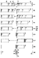
- Figs. 6A to 6I give an ideal model of a sheet deposition system limited in height by a floor 30 and a ceiling 31 and which consists of a number of deposition plates 32, 33, 34, 35, 36 and so on, which are adjustable as to height independently of one another and wherein the sheet delivery point 37 is situated approximately half way between the floor 30 and the ceiling 31, as shown in Fig. 6A.
- the model is also based on a situation in which there are two types of sheets A and B which are delivered successively and which have to be deposited separated from one another. When a sheet of type A is delivered, only plate 32 moves to beneath the delivery point 36 (Fig. 6B) and when a sheet of type B is delivered then all the plates 32, 33, 35, 36 ...
- the situation can be achieved is that the entire space between the floor 30 and the ceiling 35 is filled with sheets.
- the extra deposition capacity attainable with an extra deposition plate is practically nil. Normally, therefore, there is little logic in increasing the number of deposition plates to more than approximately 5 - 6 plates, because the available extra deposition capacity is then no longer compensated by the cost of the extra deposition plate required. If the sheets of types A and B are not deposited alternately, and instead all the sheets of type B first and then all the sheets of type A next, the same deposition capacity is obtained as shown in Fig. 6.
- Figs. 7A to 7H show a method performed with the embodiment of a printing apparatus according to the invention as shown in Fig. 1, wherein up to a maximum of 2250 sheets of a first type A can be deposited on the bottom support 16 and up to a maximum of 500 sheets of a second type B can be deposited on each of the supports 17, 18 and 19 (hence in all 3750 sheets as shown in Fig. 7A), without it being necessary to interrupt the printing process to remove sheets from the supports.
- a total of 1250 sheets is first deposited on supports 16 and 19, for example 750 sheets on support 16 and 500 sheets on support 19, as shown in Figs. 7B and 7C.
- Support 19 is then raised to a parking position and then 1000 following sheets are deposited on supports 16 and 18, e.g. 500 sheets on support 16 and 500 sheets on support 18, as shown in Figs. 7D and 7E.
- Support 18 is then also raised to a parking position and the following 750 sheets are deposited on support 16 and 17, for example 500 sheets on support 16 and 250 sheets on supports 16 as shown in Figs. 7F and 7G.
- support 17 is also raised to a parking position and a number of sheets can then be deposited in the space that has been freed on support 16, for example 750 sheets of type A on support 16 as shown in Fig. 7H.
- a requirement for a method in which the supports 17, 18 and 19 situated above the bottom support 16 can come into a parking position above the sheet delivery point is that the total number of sheets deposited on these supports 17, 18 and 19 in an uninterrupted printing process remains limited, for example, to 1500 sheets in the embodiment shown in Fig. 7.
- the available deposition capacities when solely sheets of type A are supplied is 2250 sheets, while when only sheets of type B are supplied it is 1500 sheets and in the case of a mix of sheets of types A and B the deposition capacity is often very much above 2250 sheets with a maximum of 3750 sheets.
- the deposition capacity for sheets of type B is limited to the number of sheets actually deposited on support 16 minus 750.
- a corresponding further capacity limitation can be obtained if delivery of a total of more than 1250 sheets of type A takes place before 500 sheets of type B have been deposited on support 18 and also if delivery of a total of 1500 sheets of type A takes place before 500 sheets of type B have been deposited on support 17. In all these cases, the supports 19, 18 and 17 can no longer come into a deposition position to receive 500 sheets on each of said supports.
- All the supports can be provided, at their underside, with detectors which respond to an obstacle therebeneath, e.g. to the top of a stack of sheets situated directly thereunder.
- a control system is on the one hand connected to each of these sensors and to the drive system for the height adjustment of each of the supports.
- This space can be increased by moving further downwards a support situated beneath the delivery point until the detector beneath said support again responds to an obstacle therebeneath in the form of a stack of sheets or by moving further upwards a support situated above the delivery point until the detector beneath the support thereabove again responds to an obstacle therebeneath, for example a remaining stack of sheets.
- a detector can also be disposed at a fixed position above the top support to detect a (remaining) stack of sheets on the top support in order that the top support can also be moved further upwards on removal of sheets, again to utilise the deposition space that has been freed.
- type A is formed by sheets printed on activation of the printing apparatus by an operator at the printing apparatus (interactive print jobs) and type B by sheets printed on activation of the printing apparatus by a user at a workstation at a distance from the printing apparatus (automatic print jobs).
- print jobs can also be sorted in respect of other criteria, for example:
Landscapes
- Engineering & Computer Science (AREA)
- Mechanical Engineering (AREA)
- Pile Receivers (AREA)
- Collation Of Sheets And Webs (AREA)
Abstract
Description
- The invention relates to a method of selectively depositing printed sheets fed from a fixed delivery point on at least three superposed supports of a group of supports which are adjustable as to height independently of one another, each support being adapted to be placed, for the deposition of a sheet thereon, with its support surface or the top sheet situated on the support a short fixed distance beneath the delivery point and printed sheets of a first type being deposited on at least the bottom support of the group of supports and printed sheets of a second type being deposited on supports situated thereabove of the group of supports.
A method of this kind is described in Netherlands Patent Application 1006471 filed on 4.7.1997. This patent application describes a printing apparatus in which printed sheets of the first type are formed by sheets printed after activation of the printing apparatus by operation of a button on the printing apparatus. When the operator who locally started the printing apparatus to finish his print job removes the relevant prints from the bottom support after completion of the print job, the placing of supports thereabove into a deposition position is no longer obstructed by prints situated on the bottom support and the printing apparatus can again be fully utilised to deposit prints of the second type on supports situated above the bottom support and is of course also completely available for depositing prints of the first type on the bottom support.
One consequence of this method is that it does not function efficiently if an operator leaves his finished prints on the bottom support and the bottom support is no longer available, even after removal of prints, for prints for which the printing apparatus has been activated by an operator remotely, for example from a workstation at a distance from the printing apparatus. This latter will be an obstacle particularly if in a specific period prints are requested only from workstations at a distance from the printing apparatus, which prints are often not fetched directly after completion.
In that case it is readily possible that the printing apparatus can no longer be activated when the deposition capacity of the supports situated above the bottom support has been completely utilised and the bottom support remains unused. - The object of the invention is to provide a method without the above disadvantages.
To this end, according to the invention, out of a group of sheets of the second type for deposition a first part is first deposited on a higher-level support and then a second part is deposited on a support therebeneath. As a result, even if prints are not removed from the associated support directly after completion of a print job the average deposition capacity remains large, particularly because prints which might be lying on supports situated between the higher-level support and the bottom support do not obstruct the higher-level support being moved into the deposition position.
Preferably, the first part of the group of sheets of the second type contains more sheets than the second part of the group of sheets of the second type. Consequently, a relatively large number of sheets of the second type can be deposited without the interim removal of sheets, because in the initial period of deposition on the higher-level support there is a greater probability that still relatively few sheets are deposited on the bottom support so that the top support can come into a low deposition position to receive a large number of sheets. - In one advantageous embodiment, a portion of sheets for deposition of the first type which are to be distinguished are deposited on the support situated directly above the bottom support.
Consequently, printed sheets of the first type printed as an intermediate print job during an interruption of a print job for printing sheets of the same type are deposited on a support specially reserved for the purpose so that they can be readily located. - In a further advantageous method according to the invention, in a first deposition cycle sheets are deposited selectively on the bottom support and on the top support of the group until at least the number of sheets on the bottom support reaches a height "a" corresponding to half the distance between the delivery point and the lowest possible position of the bottom support and that in following deposition cycles in each case sheets are deposited selectively on the bottom support and, counting from the top, on the next free support of the group until at least the number of sheets on the bottom support reaches a height corresponding to the height "a" plus in each case half the height of the sheets deposited on the bottom support in the preceding deposition cycle. One embodiment of a sheet deposition device for performing the method according to the invention comprises drive means at each support for adjusting the same as to height, and also control means which, in an initialisation cycle, on adjustment of the sheet deposition device to the deposition of sheets of the first type, activate the drive means for the supports in order to move the supports situated above the bottom support to a position above the delivery point and the bottom support into its deposition position, at least insofar as there is room for movement for this purpose, and, on adjustment of the sheet deposition device to the deposition of sheets of the second type, activate the drive means for the supports to move the top support into its deposition position and the supports situated beneath the top support to directly therebeneath, again insofar as there is room for movement for the purpose, the control means, when a predetermined number of sheets has been delivered on the top support, moves said support to above the delivery point and the support directly therebeneath into its deposition position. The effect of this embodiment is that on each initialisation of this sheet deposition device according to the invention a check is made whether on deposition of sheets of the second type there is still deposition space available on the top support, or such space has been freed by removal, so that in that case deposition on the top support takes place first before proceeding to deposition on the support situated directly therebeneath. This ensures that the deposition space for sheets of the second type is used in the optimum manner.
In a further embodiment of a sheet deposition device according to the invention, in which the drive means can move a support up and down between the deposition position in which sheets can be deposited on said support and a parking position in which sheet deposition is not possible, each support is provided with detection means for detecting an obstacle in the space directly therebeneath, for example sheets on a support situated directly therebeneath, which detection means deliver a first detection signal when the distance between the support provided with said detection means and an obstacle directly therebeneath is greater than a predetermined amount in order to make the drive means capable of activation.
The effect of this is that the free space between the supports can be restricted to a minimum in order to obtain maximum deposition capacity.
Other features and advantages of the invention will be explained hereinafter with reference to the accompanying drawings wherein: - Fig. 1 illustrates one embodiment of a printing apparatus according to the invention,
- Fig. 2 shows a part of the printing apparatus shown in Fig. 1 in a position in which sheets are deposited on the bottom support,
- Fig. 3 shows the part of the printing apparatus according to Fig. 2 in a position in which sheets are deposited on the top support,
- Fig. 4 shows the part of the printing apparatus of Fig. 2 in a position in which sheets are deposited on the support situated directly beneath the top support,
- Fig. 5 shows the part of the printing apparatus of Fig. 2 in which sheets are deposited on the bottom support without sheets having been removed from the supports thereabove,
- Fig. 6 A to I illustrates an ideal model of a sheet deposition system according to the invention,
- Fig. 7 A to H shows a practical embodiment of a method according to the model shown in Fig. 6 and
- Fig. 8 shows detection means mounted beneath each support.
-
- The
printing apparatus 1 shown in Fig. 1 comprises means known per se for printing an image on a receiving sheet. These images for printing may be present on original documents which are fed to ascanning station 2 situated at the top of theprinting apparatus 1. Images for printing can also be fed in digital form from a workstation 3 connected via a network 4 to acontrol device 8 of theprinting apparatus 1. A printing cycle for copying an original set fed via thescanning station 2 is started by actuating a start button 6 on the operator control panel 5 of theprinting apparatus 1.
A printing cycle for printing an image set fed via workstation 3 can be started by actuating a start button 7 provided on the workstation 3, via control device 8 (hereinafter referred to as automatic printing), or by actuating a start button 6 provided on the operator control panel 5 of the printing apparatus 1 (hereinafter referred to as semi-automatic printing). - In the
printing apparatus 1 shown in Fig. 1, thesheet transport path 10 forms the path for delivering to asheet finishing station 11 the sheets printed in the printing apparatus.
Thefinishing station 11 contains a sheet collecting tray 12 (not shown in detail) in which a number of printed sheets belonging to a set can be collected and stapled, whereafterdischarge roller pairs 13 feed the set to asheet deposition unit 15 forming part of asheet deposition station 11.
Thesheet deposition unit 15 comprises four superposed deposition tables 16, 17, 18 and 19, each of which can be set to a deposition position with respect to the horizontal discharge path formed by thedischarge roller pair 13, to receive sheets discharged by thedischarge roller pair 13. The vertical displacement of the deposition tables can be effected by means of the displacement mechanism described in European Patent Specification 0 532 069, the selected deposition table or the sheet at the top thereof always lying just beneath the discharge path formed by thedischarge roller pair 13. Fig. 1 shows the bottom deposition table 16 in a bottom deposition position in which a number of sheets are situated on said deposition table 16 and the deposition tables 17, 18 and 19 situated thereabove are in parking positions situated above the discharge path formed by thedischarge roller pair 13.
Since the deposition tables 17, 18 and 19 are adjustable as to height independently of deposition table 16, the top deposition table 19 can be placed in a deposition position without the bottom deposition table 16 needing to be moved further down than the bottom deposition position shown in Fig. 1.
As a result, thefinishing station 11 with thesheet deposition unit 15 adjacent the same is very suitable for disposing at the top of aprinting apparatus 1, the top of which with thescanning station 2 is situated at a normal working height for a standing operator of about 100 cm. In theprinting apparatus 1 with thefinishing station 11 as shown in Fig. 1, the removal height for sheets deposited on deposition tables 16, 17, 18 and 19 is between 100 cm and 160 cm for a total sheet deposition capacity of about 3000 sheets. The sheet deposition level defined by thefixed discharge rollers 13 is approximately 133 cm, and this level corresponds to the deposition level at which the bottom deposition table 16 is in its bottom deposition position.
The combination of high deposition capacity and limited overall height is rendered possible by using the printing apparatus in accordance with the steps according to the invention, namely by using the bottom deposition table 16 solely for the deposition of prints of a first type, the printing cycle of which is initiated with a setting button on the printing apparatus, so that the operator who makes this setting can also remove the deposited prints shortly thereafter, giving the deposition tables situated thereabove the opportunity to come into their deposition position and receive prints of a second type, the printing cycle of which is initiated from a workstation 3 at a distance from the printing apparatus. - The operation of the printing apparatus according to the invention will now be explained further with reference to Figs. 2 to 5, which show in greater detail and in different positions the
deposition station 11 shown in Fig. 1. - Figs. 6A to 6I give an ideal model of a sheet deposition system limited in height by a
floor 30 and aceiling 31 and which consists of a number ofdeposition plates sheet delivery point 37 is situated approximately half way between thefloor 30 and theceiling 31, as shown in Fig. 6A. The model is also based on a situation in which there are two types of sheets A and B which are delivered successively and which have to be deposited separated from one another.
When a sheet of type A is delivered, onlyplate 32 moves to beneath the delivery point 36 (Fig. 6B) and when a sheet of type B is delivered then all theplates delivery point 37 and floor 30 (Fig. 6C).Plate 36 is then moved away completely above the delivery point (Fig. 6D). Further sheets for deposition are now deposited alternately on thebottom plate 32 and the top plate but one (35 in this case) until the number of sheets onplate 35 amounts to half the number of sheets onplate 36. This situation is shown in Fig. 6E.
Plate 35 is then moved away completely above the delivery point 36 (Fig. 6F) and the deposition process continues with tables 32 and 34 until table 34 accommodates half the number of sheets lying on table 35. The same then takes place with tables 32 and 33. The situation shown in Fig. 6I is finally reached.
Given an infinite number of extremely thin plates, the situation can be achieved is that the entire space between thefloor 30 and theceiling 35 is filled with sheets. In view of the necessary thickness of the plates, the extra deposition capacity attainable with an extra deposition plate is practically nil. Normally, therefore, there is little logic in increasing the number of deposition plates to more than approximately 5 - 6 plates, because the available extra deposition capacity is then no longer compensated by the cost of the extra deposition plate required.
If the sheets of types A and B are not deposited alternately, and instead all the sheets of type B first and then all the sheets of type A next, the same deposition capacity is obtained as shown in Fig. 6.
However, if sheets of type A are first to be deposited up to the maximum deposition capacity ofplate 32 and only then sheets of type B, then there is no longer any room for the latter.
Since the distribution of the delivery of sheets of types A and B is usually not preset, the available deposition capacity will vary between a number of sheets corresponding to the distance between thefloor 30 anddelivery point 37 and thefloor 30 andceiling 31. Since the deposition space freed as the last occurs when the bottom deposition table but one is moved aside to above the delivery point, a maximum deposition capacity can be achieved with a limited number of deposition tables if a number of sheets of type A is deposited as the last on the bottom support. In the case of a printing apparatus which normally prints sheets of types A and B in a specific alternation, this can be achieved by storing in a memory a number of images A which are to be printed as the last, said number corresponding to the number of sheets of type B deposited on the bottom table but one, and by not printing the stored images A until the said number has been deposited on the bottom table but one. - Figs. 7A to 7H show a method performed with the embodiment of a printing apparatus according to the invention as shown in Fig. 1, wherein up to a maximum of 2250 sheets of a first type A can be deposited on the
bottom support 16 and up to a maximum of 500 sheets of a second type B can be deposited on each of thesupports
Starting from a situation in which the sheet deposition device is empty, a total of 1250 sheets is first deposited onsupports support support 19, as shown in Figs. 7B and 7C.Support 19 is then raised to a parking position and then 1000 following sheets are deposited onsupports support support 18, as shown in Figs. 7D and 7E.
Support 18 is then also raised to a parking position and the following 750 sheets are deposited onsupport support supports 16 as shown in Figs. 7F and 7G.
Finally,support 17 is also raised to a parking position and a number of sheets can then be deposited in the space that has been freed onsupport 16, for example 750 sheets of type A onsupport 16 as shown in Fig. 7H.
A requirement for a method in which thesupports bottom support 16 can come into a parking position above the sheet delivery point is that the total number of sheets deposited on thesesupports
If, in the case of a mixed delivery, a total of more than 750 sheets of type A takes place before 500 sheets of type B have been deposited onsupport 19, the deposition capacity for sheets of type B is limited to the number of sheets actually deposited onsupport 16minus 750.
A corresponding further capacity limitation can be obtained if delivery of a total of more than 1250 sheets of type A takes place before 500 sheets of type B have been deposited onsupport 18 and also if delivery of a total of 1500 sheets of type A takes place before 500 sheets of type B have been deposited onsupport 17. In all these cases, thesupports - All the supports can be provided, at their underside, with detectors which respond to an obstacle therebeneath, e.g. to the top of a stack of sheets situated directly thereunder.
A control system is on the one hand connected to each of these sensors and to the drive system for the height adjustment of each of the supports. When sheets are removed from a support in a parking position, the distance between the remaining sheets and a support situated directly thereabove increases and the detector beneath said support comes out of the range of the remaining sheets and consequently extra deposition space becomes available. This space can be increased by moving further downwards a support situated beneath the delivery point until the detector beneath said support again responds to an obstacle therebeneath in the form of a stack of sheets or by moving further upwards a support situated above the delivery point until the detector beneath the support thereabove again responds to an obstacle therebeneath, for example a remaining stack of sheets.
A detector can also be disposed at a fixed position above the top support to detect a (remaining) stack of sheets on the top support in order that the top support can also be moved further upwards on removal of sheets, again to utilise the deposition space that has been freed. - In a practical application of the method described hereinbefore (walk up priority printing"), type A is formed by sheets printed on activation of the printing apparatus by an operator at the printing apparatus (interactive print jobs) and type B by sheets printed on activation of the printing apparatus by a user at a workstation at a distance from the printing apparatus (automatic print jobs).
In addition to "walk up priority" printing, print jobs can also be sorted in respect of other criteria, for example: - jobs from a first group of users on the bottom support or supports and jobs from a second group of users on the top support or supports
- jobs with stapled sheet sets on the top support or supports, for example a maximum of 500 stapled sheets on each of the two top supports and jobs with non-stapled sheet sets on the bottom support or supports, for example 2250 sheets and 500 non-stapled sheets respectively on the two bottom supports.
Furthermore, one support can remain unused in the case of sorting of print jobs over two deposition classes, for example, for example the second support from the bottom in order to reserve it and mark it for intermediate jobs. The advantage of this is that it is clear to a user having an intermediate job where said user can remove his intermediate job and there is no need for him to look between the jobs deposited on the other supports.
The above-mentioned top-down algorithm is also usable for one deposition class, in which when the supports are filled from the top to the bottom, the attempt is again made to provide top-down deposition for subsequent jobs for deposition, use being made of the space freed by printed sheets being removed from the supports. A condition for this is that it is possible to detect that sheets have been removed from supports.
For detection suitable for the purpose beneath the supports for sheet stacks, each deposition table 16, 17, 18 and 19 is provided with two
A
Upright parts of the
A U-shaped
When a deposition table moves down and the
An opto-
The switching time is so chosen that
The use of the switch arm 53, situated around the straps between the deposition plate and the switch plate, ensures a flat construction which, for example, has a total overall height of only 20 mm with the required stroke length of 7 mm for the switch plate, of which, for example, 4 mm is for the opto-electrical switches and 3 mm for the protective microswitch.
At the
Claims (11)
- A method of selectively depositing printed sheets fed from a fixed delivery point (13; 37) on at least three superposed supports (16, 17, 18, 19; 32, 33, 34, 35, 36) of a group of supports which are adjustable as to height independently of one another, each support (16, 17, 18, 19; 32, 33, 34, 35, 36) being adapted to be placed, for the deposition of a sheet thereon, with its support surface or the top sheet situated on the support a short fixed distance beneath the delivery point (13; 37) and printed sheets of a first type (A) being deposited on at least the bottom support (16; 32) of the group of supports and printed sheets of a second type (B) being deposited on supports (17, 18, 19; 33, 34, 35, 36) situated thereabove of the group of supports, characterised in that out of a group of sheets of the second type (B) for deposition a first part is first deposited on a higher-level support (19, 18; 36, 35, 34) and then a second part is deposited on a support (18, 17; 35, 34, 33) therebeneath.
- A method according to claim 1, characterised in that the first part of the group of sheets of the second type (B) comprises more sheets than the second part of the group of sheets of the second type (B).
- A method according to claim 1 or 2, characterised in that a portion of sheets for deposition of the first type (A) which are to be distinguished are deposited on the support (17; 33) situated directly above the bottom support (16; 32).
- A method according to claim 1 or 2, characterised in that in a first deposition cycle (Fig. 6B/6C; Fig. 7B/7C) sheets are deposited selectively on the bottom support (16; 32) and on the top support (19; 37) of the group until at least the number of sheets on the bottom support (16; 32) reaches "a" height a corresponding to half the distance between the delivery point (13; 37) and the lowest possible position (30) of the bottom support (16; 32) and that in following deposition cycles in each case sheets are deposited selectively on the bottom support (16; 32) and, counting from the top, on the next free support (18; 35 and 17; 34 respectively) of the group until at least the number of sheets on the bottom support reaches a height corresponding to the height "a" plus in each case half the height of the sheets deposited on the bottom support (16; 32) in the preceding deposition cycle.
- A sheet deposition device (15) for performing the method according to any one of the preceding claims, comprising drive means at each support (16, 17, 18, 19; 32, 33, 34, 35, 36) for adjusting the same as to height, characterised in that control means (8) are provided which in an initialisation cycle, on adjustment of the sheet deposition device (15) to the deposition of sheets of the first type (A), activate the drive means for the supports in order to move the supports (17, 18, 19; 33, 34, 35, 36) situated above the bottom support (16; 32) to a position above the delivery point (13; 37) and the bottom support (16; 32) into its deposition position, at least insofar as there is room for movement for this purpose, and, on adjustment of the sheet deposition device (15) to the deposition of sheets of the second type (B), activate the drive means for the supports to move the top support (19; 36) into its deposition position and the supports (17, 18; 33, 34, 35) situated beneath the top support (19; 32) to directly therebeneath, again insofar as there is room for movement for the purpose, and in that the control means (8), when a predetermined number of sheets has been delivered on the top support (19; 36), moves said support to above the delivery point (13; 37) and the support directly therebeneath into its deposition position.
- A sheet deposition device according to claim 5, in which the drive means can move a support up and down between a deposition position in which sheets can be deposited on said support and a parking position in which sheet deposition is not possible, characterised in that each support is provided with detection means (Fig. 8) for detecting an obstacle in the space directly therebeneath, for example sheets on a support situated directly therebeneath, which detection means deliver a first detection signal when the distance between the support provided with said detection means and an obstacle directly therebeneath is greater than a predetermined amount in order to make the drive means capable of activation.
- A sheet deposition device according to claim 6, characterised in that first control means are provided which in response to the reception of a first detection signal delivered by the detection means at a support which is in a deposition position, make the drive means of said support capable of activation to move said support down on deposition of subsequent sheets thereon.
- A sheet deposition device according to claim 6 or 7, characterised in that second control means are provided which in response to the reception of a first detection signal delivered by the detection means at a support in a parking position and lower than a support in a deposition position, activate the drive means of said support in order to move said support downwards.
- A sheet deposition device according to any one of claims 6 to 8, characterised in that third control means are provided which in response to the reception of a first detection signal delivered by the detection means at a support situated above a support in a parking position directly above a support in a deposition position activate the drive means at the support in a parking position directly above a support in the deposition position in order to raise the support directly above the support in the deposition position.
- A sheet deposition device according to any one of claims 6 to 9, characterised in that further detection means are fixed above the top support for detecting sheets on said top support and deliver a first detection signal when the distance between the fixed detection means and the top sheet on the top support is greater than a predetermined amount.
- A sheet deposition device according to claim 10, characterised in that fourth control means are provided which in response to the reception of a first detection signal delivered by the fixed detection means activate the drive means at the top support to raise the top support.
Applications Claiming Priority (2)
| Application Number | Priority Date | Filing Date | Title |
|---|---|---|---|
| NL1012924A NL1012924C2 (en) | 1999-08-27 | 1999-08-27 | Method and device for selectively depositing printed sheets on superimposed carriers. |
| NL1012924 | 1999-08-27 |
Publications (2)
| Publication Number | Publication Date |
|---|---|
| EP1078873A1 true EP1078873A1 (en) | 2001-02-28 |
| EP1078873B1 EP1078873B1 (en) | 2004-03-31 |
Family
ID=19769796
Family Applications (1)
| Application Number | Title | Priority Date | Filing Date |
|---|---|---|---|
| EP00202855A Expired - Lifetime EP1078873B1 (en) | 1999-08-27 | 2000-08-15 | Method of and apparatus for selectively depositing printed sheets on superposed supports |
Country Status (5)
| Country | Link |
|---|---|
| US (1) | US6412994B1 (en) |
| EP (1) | EP1078873B1 (en) |
| JP (1) | JP4705230B2 (en) |
| DE (1) | DE60009405T2 (en) |
| NL (1) | NL1012924C2 (en) |
Cited By (2)
| Publication number | Priority date | Publication date | Assignee | Title |
|---|---|---|---|---|
| EP1588972A1 (en) * | 2004-04-19 | 2005-10-26 | Canon Finetech Inc. | Sheet treating apparatus and image forming apparatus provided therewith |
| EP4582363A1 (en) * | 2024-01-05 | 2025-07-09 | Canon Kabushiki Kaisha | A method of stacking printed sheets in a printer |
Families Citing this family (5)
| Publication number | Priority date | Publication date | Assignee | Title |
|---|---|---|---|---|
| JP4174442B2 (en) * | 2004-03-15 | 2008-10-29 | 富士通株式会社 | Paper sheet bundle height detection method and paper sheet handling apparatus |
| JP4662422B2 (en) * | 2004-04-19 | 2011-03-30 | キヤノンファインテック株式会社 | Sheet processing apparatus and image forming apparatus having the same |
| JP2006315812A (en) * | 2005-05-13 | 2006-11-24 | Canon Inc | Sheet processing apparatus and image forming apparatus |
| EP1834797A1 (en) * | 2006-03-17 | 2007-09-19 | Seiko Epson Corporation | Stacker position changer and recording apparatus or liquid ejecting apparatus incorporating the same |
| JP5279543B2 (en) * | 2008-03-07 | 2013-09-04 | キヤノン株式会社 | Sheet stacking apparatus, sheet processing apparatus, and image forming apparatus |
Citations (4)
| Publication number | Priority date | Publication date | Assignee | Title |
|---|---|---|---|---|
| US5106076A (en) * | 1990-07-02 | 1992-04-21 | Mita Industrial Co., Ltd. | Sorter controller |
| EP0532069A1 (en) * | 1991-08-01 | 1993-03-17 | Océ-Nederland B.V. | A device for depositing sheets on supports situated one above the other |
| EP0872777A1 (en) * | 1997-04-18 | 1998-10-21 | Riso Kagaku Corporation | Sheet sorter and method of controlling the sheet sorter |
| NL1006471C2 (en) * | 1997-07-04 | 1999-01-05 | Oce Tech Bv | Printing device with selective deposition of printed sheets on height-adjustable carriers. |
Family Cites Families (11)
| Publication number | Priority date | Publication date | Assignee | Title |
|---|---|---|---|---|
| US4349190A (en) * | 1979-09-29 | 1982-09-14 | Ricoh Co., Ltd. | Sheet classifying system having deflecting device |
| US4782363A (en) * | 1987-09-17 | 1988-11-01 | Xerox Corporation | Copying system for on-line finishing |
| JP3227220B2 (en) * | 1992-09-24 | 2001-11-12 | キヤノン株式会社 | Sheet post-processing equipment |
| US5535012A (en) * | 1993-07-31 | 1996-07-09 | Canon Kabushiki Kaisha | Information transmit/receive apparatus onto which a sorter can be mounted via an adapter |
| JPH0873107A (en) * | 1994-09-05 | 1996-03-19 | Canon Inc | Sorting device and image forming device |
| EP0807596B1 (en) * | 1996-05-13 | 2002-08-07 | Riso Kagaku Corporation | Sheet sorter |
| JPH1059613A (en) * | 1996-08-19 | 1998-03-03 | Ricoh Co Ltd | Discharge mechanism of image forming apparatus |
| JP3542474B2 (en) * | 1997-11-19 | 2004-07-14 | キヤノン株式会社 | Sheet processing apparatus and image forming apparatus having the same |
| US6231045B1 (en) * | 1998-06-12 | 2001-05-15 | Ricoh Company, Ltd. | Finisher for an image forming apparatus |
| US6227539B1 (en) * | 1998-10-21 | 2001-05-08 | Xerox Corporation | Printer mailboxing system with automatic variable capacity bins |
| US6247695B1 (en) * | 1998-12-23 | 2001-06-19 | Xerox Corporation | Multiple zone stack height sensor for high capacity feeder |
-
1999
- 1999-08-27 NL NL1012924A patent/NL1012924C2/en not_active IP Right Cessation
-
2000
- 2000-08-15 EP EP00202855A patent/EP1078873B1/en not_active Expired - Lifetime
- 2000-08-15 DE DE60009405T patent/DE60009405T2/en not_active Expired - Lifetime
- 2000-08-25 JP JP2000256139A patent/JP4705230B2/en not_active Expired - Fee Related
- 2000-08-25 US US09/648,110 patent/US6412994B1/en not_active Expired - Lifetime
Patent Citations (5)
| Publication number | Priority date | Publication date | Assignee | Title |
|---|---|---|---|---|
| US5106076A (en) * | 1990-07-02 | 1992-04-21 | Mita Industrial Co., Ltd. | Sorter controller |
| EP0532069A1 (en) * | 1991-08-01 | 1993-03-17 | Océ-Nederland B.V. | A device for depositing sheets on supports situated one above the other |
| EP0872777A1 (en) * | 1997-04-18 | 1998-10-21 | Riso Kagaku Corporation | Sheet sorter and method of controlling the sheet sorter |
| NL1006471C2 (en) * | 1997-07-04 | 1999-01-05 | Oce Tech Bv | Printing device with selective deposition of printed sheets on height-adjustable carriers. |
| EP0888994A1 (en) * | 1997-07-04 | 1999-01-07 | Océ-Technologies B.V. | A printing apparatus for selective deposition of printed sheets on supports which are adjustable as to height |
Cited By (3)
| Publication number | Priority date | Publication date | Assignee | Title |
|---|---|---|---|---|
| EP1588972A1 (en) * | 2004-04-19 | 2005-10-26 | Canon Finetech Inc. | Sheet treating apparatus and image forming apparatus provided therewith |
| US7571909B2 (en) | 2004-04-19 | 2009-08-11 | Canon Finetech Inc. | Sheet treating apparatus and image forming apparatus provided therewith |
| EP4582363A1 (en) * | 2024-01-05 | 2025-07-09 | Canon Kabushiki Kaisha | A method of stacking printed sheets in a printer |
Also Published As
| Publication number | Publication date |
|---|---|
| US6412994B1 (en) | 2002-07-02 |
| NL1012924C2 (en) | 2001-02-28 |
| JP4705230B2 (en) | 2011-06-22 |
| JP2001097629A (en) | 2001-04-10 |
| DE60009405T2 (en) | 2005-03-03 |
| EP1078873B1 (en) | 2004-03-31 |
| DE60009405D1 (en) | 2004-05-06 |
Similar Documents
| Publication | Publication Date | Title |
|---|---|---|
| EP0888994B1 (en) | A printing apparatus for selective deposition of printed sheets on supports which are adjustable as to height | |
| US5609333A (en) | Sheet stack height control system | |
| CA2183384C (en) | Single stack height sensor for plural sheet stacking bins system | |
| DE69611649T2 (en) | System for correcting a stack height estimate | |
| EP0729078B1 (en) | Printer and mailboxing system with banner sheet indicator system for split jobs | |
| EP1078873B1 (en) | Method of and apparatus for selectively depositing printed sheets on superposed supports | |
| US20040051238A1 (en) | Finisher for an image forming apparatus | |
| CN102411275B (en) | Image forming apparatus and image formation system and control method thereof | |
| US4927131A (en) | Sheet stacking apparatus | |
| US6361039B1 (en) | Sheet deposition device for selective deposition of sheets on superimposed supports | |
| US5598258A (en) | Image forming apparatus with interconnected sorters and control device therefor | |
| JP3414772B2 (en) | Device for depositing sheets on supports arranged one above the other | |
| JP3822290B2 (en) | Mailbox system | |
| JP3797738B2 (en) | Paper take-out device | |
| JPH0776069B2 (en) | Copying device | |
| EP1500516A1 (en) | Apparatus and method for distributing print media | |
| JP2001335229A (en) | Post processing device for printer | |
| JPH1148596A (en) | Paper receiver and paper feeder for rotary stencil printer | |
| JP2000159418A (en) | Image forming device | |
| US20030123895A1 (en) | Paper discharging mechanism of image forming apparatus | |
| JP7409071B2 (en) | Image forming system and discharge method | |
| JP3337500B2 (en) | Seat storage device | |
| JP3768000B2 (en) | Paper processing device | |
| JPH09114326A (en) | Image forming device | |
| JP2005001859A (en) | Image forming apparatus |
Legal Events
| Date | Code | Title | Description |
|---|---|---|---|
| PUAI | Public reference made under article 153(3) epc to a published international application that has entered the european phase |
Free format text: ORIGINAL CODE: 0009012 |
|
| AK | Designated contracting states |
Kind code of ref document: A1 Designated state(s): DE FR GB NL |
|
| AX | Request for extension of the european patent |
Free format text: AL;LT;LV;MK;RO;SI |
|
| 17P | Request for examination filed |
Effective date: 20010828 |
|
| AKX | Designation fees paid |
Free format text: DE FR GB NL |
|
| 17Q | First examination report despatched |
Effective date: 20021015 |
|
| GRAP | Despatch of communication of intention to grant a patent |
Free format text: ORIGINAL CODE: EPIDOSNIGR1 |
|
| GRAS | Grant fee paid |
Free format text: ORIGINAL CODE: EPIDOSNIGR3 |
|
| GRAA | (expected) grant |
Free format text: ORIGINAL CODE: 0009210 |
|
| AK | Designated contracting states |
Kind code of ref document: B1 Designated state(s): DE FR GB NL |
|
| REG | Reference to a national code |
Ref country code: GB Ref legal event code: FG4D |
|
| REF | Corresponds to: |
Ref document number: 60009405 Country of ref document: DE Date of ref document: 20040506 Kind code of ref document: P |
|
| ET | Fr: translation filed | ||
| PLBE | No opposition filed within time limit |
Free format text: ORIGINAL CODE: 0009261 |
|
| STAA | Information on the status of an ep patent application or granted ep patent |
Free format text: STATUS: NO OPPOSITION FILED WITHIN TIME LIMIT |
|
| 26N | No opposition filed |
Effective date: 20050104 |
|
| REG | Reference to a national code |
Ref country code: FR Ref legal event code: PLFP Year of fee payment: 17 |
|
| PGFP | Annual fee paid to national office [announced via postgrant information from national office to epo] |
Ref country code: NL Payment date: 20160817 Year of fee payment: 17 |
|
| PGFP | Annual fee paid to national office [announced via postgrant information from national office to epo] |
Ref country code: GB Payment date: 20160819 Year of fee payment: 17 Ref country code: DE Payment date: 20160822 Year of fee payment: 17 |
|
| PGFP | Annual fee paid to national office [announced via postgrant information from national office to epo] |
Ref country code: FR Payment date: 20160822 Year of fee payment: 17 |
|
| REG | Reference to a national code |
Ref country code: DE Ref legal event code: R119 Ref document number: 60009405 Country of ref document: DE |
|
| REG | Reference to a national code |
Ref country code: NL Ref legal event code: MM Effective date: 20170901 |
|
| GBPC | Gb: european patent ceased through non-payment of renewal fee |
Effective date: 20170815 |
|
| REG | Reference to a national code |
Ref country code: FR Ref legal event code: ST Effective date: 20180430 |
|
| PG25 | Lapsed in a contracting state [announced via postgrant information from national office to epo] |
Ref country code: NL Free format text: LAPSE BECAUSE OF NON-PAYMENT OF DUE FEES Effective date: 20170901 |
|
| PG25 | Lapsed in a contracting state [announced via postgrant information from national office to epo] |
Ref country code: DE Free format text: LAPSE BECAUSE OF NON-PAYMENT OF DUE FEES Effective date: 20180301 Ref country code: GB Free format text: LAPSE BECAUSE OF NON-PAYMENT OF DUE FEES Effective date: 20170815 |
|
| PG25 | Lapsed in a contracting state [announced via postgrant information from national office to epo] |
Ref country code: FR Free format text: LAPSE BECAUSE OF NON-PAYMENT OF DUE FEES Effective date: 20170831 |