EP1078819A2 - Structure for reducing wind noise - Google Patents
Structure for reducing wind noise Download PDFInfo
- Publication number
- EP1078819A2 EP1078819A2 EP00111273A EP00111273A EP1078819A2 EP 1078819 A2 EP1078819 A2 EP 1078819A2 EP 00111273 A EP00111273 A EP 00111273A EP 00111273 A EP00111273 A EP 00111273A EP 1078819 A2 EP1078819 A2 EP 1078819A2
- Authority
- EP
- European Patent Office
- Prior art keywords
- flow
- wind noise
- vehicle
- reducing wind
- cross
- Prior art date
- Legal status (The legal status is an assumption and is not a legal conclusion. Google has not performed a legal analysis and makes no representation as to the accuracy of the status listed.)
- Granted
Links
- 230000006835 compression Effects 0.000 claims abstract description 24
- 238000007906 compression Methods 0.000 claims abstract description 24
- 238000000926 separation method Methods 0.000 claims abstract description 18
- 230000001105 regulatory effect Effects 0.000 description 3
- 230000000694 effects Effects 0.000 description 2
- 230000002787 reinforcement Effects 0.000 description 1
- 239000011347 resin Substances 0.000 description 1
- 229920005989 resin Polymers 0.000 description 1
Images


Classifications
-
- B—PERFORMING OPERATIONS; TRANSPORTING
- B60—VEHICLES IN GENERAL
- B60R—VEHICLES, VEHICLE FITTINGS, OR VEHICLE PARTS, NOT OTHERWISE PROVIDED FOR
- B60R9/00—Supplementary fittings on vehicle exterior for carrying loads, e.g. luggage, sports gear or the like
- B60R9/04—Carriers associated with vehicle roof
- B60R9/05—Carriers characterised by wind deflecting means
Definitions
- the present invention relates to a structure for reducing wind noise.
- the structure for reducing wind noise is provided above a roof of a vehicle along the width of the vehicle.
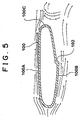
- a vehicle is equipped with a roof spoiler 100 on a roof of the vehicle at a predetermined height along the width of the vehicle.
- the roof spoiler 100 has a structure for reducing wind noise.
- the roof spoiler 100 comprises two surfaces, which are an upper surface 100A and a lower surface 100B.
- a flow regulating means 102 is shaped at least on one of two surfaces (It is the lower surface in the case shown in Fig.5.).
- the flow regulating means 102 regulates a direction of the air flow flowing along the surfaces of the roof spoiler 100 to a predetermined direction, so that two pressures or two velocities generated along the upper and lower surfaces 100A, 100B of the roof spoiler 100 are unbalanced at the place near the rear end portion 100C.
- the distance between the very front and the very rear of the roof spoiler 100 is not unnecessarily long. That is, the size of the roof spoiler 100 is restrained, and a Karman vortex of the air flow is reduced. Accordingly, a wind noise of the roof spoiler 100 is reduced.
- the difference between two pressures or velocities of the upper and lower air flows along the roof spoiler 100 might not be sufficiently high, because the flow regulating means 102 is shaped at least on one of the upper and lower surfaces 100A and 100B. It might result in not sufficiently eliminating the Karman vortex, which is the cause of the wind noise. It means that the wind noise might not be reduced efficiently by the above-mentioned structure for reducing wind noise.
- the object of the invention is to provide a structure for reducing wind noise efficiently.
- a structure for reducing wind noise provided above a roof along the width of a vehicle comprises an upper surface and a lower surface of the structure.
- the upper surface introduces an attached flow of air from the front of the vehicle to the rear of the vehicle.
- the lower surface of the structure comprises a flow compression face, a flow leading face, and a flow separation portion.
- the flow compression face in the front of the lower surface introduces and compresses the air flow from the front of the vehicle.
- the flow leading face in the center of the lower surface leads the air flow compressed from the front of the structure to the rear of the structure.
- the flow separation portion in the rear of the lower surface separates the air flow from the front of the structure.
- the lower flow of the air from the front of the vehicle and above the roof of the vehicle is first introduced to the roof side and compressed by the flow compression face in the front of the lower surface. Accordingly, the pressure of the air flow increases.
- the air flow is lead to the rear of the structure by the flow leading face in the center of the lower surface, and the air flow is separated from the structure by the flow separation portion in the rear of the lower surface.
- the separated air flow unites together with the air flow along the upper surface of the structure, Consequently, the difference of the pressures, the velocities, or etc. between the two air flow separated to the lower and upper sides of the structure is greater.
- a Karman vortex which causes a wind noise of the structure can be avoided, though a front-rear length of the structure is not unnecessary long. In these ways the wind noise of the structure can efficiently be reduced.
- the above-mentioned flow compression face is hollowed toward the center point of the cross-section of the structure, the flow leading face is a smooth convex arc of a circle as the cross-section, and the flow separation portion is notch shaped like a step.
- the air flow is led to the rear of the structure by the flow leading face which cross-sectional line is the smooth convex arc of the circle, and the air flow is separated from the structure by the flow separation portion which is notch shaped like a step.
- the separated air flow unites together with the upper air flow of the structure in the rear of the structure. Consequently, as mentioned above, the difference of the pressures, the velocities, or etc. between the two air flows separated to the lower and upper sides of the structure is greater. Then, a Karman vortex which causes a wind noise can be avoided, and the wind noise of the structure can be reduced efficiently.
- the upper surface of the structure is smoothly curved and convex toward the upper direction.
- the above-mentioned upper surface of the structure can restrain the separation of the air flow along the upper surface of the structure. Consequently, a Karman vortex which causes a wind noise can be sufficiently avoided, and the wind noise of the structure can be reduced efficiently.
- the vertical center line connecting the middle point on the upper surface from the view point of the front-rear direction with the center point of the cross-section of the structure coincides or substantially coincides with the normal line of the roof of the vehicle.
- the horizontal center line of the structure is parallel or substantially parallel to the flowing line of the air along the roof of the vehicle, and the horizontal center line is parallel or substantially parallel to a line which is tangent to the roof line as the cross-section. Accordingly, the air flow is compressed efficiently between the flow compression face and the surface of the roof. Then, the wind noise of the structure is further efficiently reduced.
- the arrow FR shows the front direction of a vehicle and the arrow UP shows the upward direction of the vehicle.
- a vehicle 10 is equipped with a roof rack 16 including two cross bars ( A cross bar is also called a structure.) 12, 14 upward on a roof 11 of the vehicle 10.
- the front crossbar 12 and the rear crossbar 14 are respectively at the front and rear of the roof 11 of the vehicle 10.
- the crossbars 12, 14 are substantially parallel along the width of the vehicle 10.
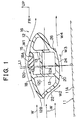
- Fig. 1 shows a cross-sectional view of the front cross bar 12.
- an upper surface 18 of the front cross bar 12 is shaped as an upward smooth convex (for example, a convex arc of a circle), and the upper surface 18 leads some part (shown as an arrow W1 in Fig. 1) of an air flow (shown as an arrow W) from the front to the rear of the vehicle 10.
- the front cross bar 12 is made from resin, and a reinforcement rib 13 is provided inside of the front cross bar 12.
- a cushion 15, for example a rubber cushion, is fixed on the front cross bar 12. The cushion 15 is for softly receiving a carried object or carried objects put on the roof rack 16.
- a flow compression face 22 is shaped at the front face of a lower surface 20 of the front crossbar 12.
- the flow compression face 22 is hollowed toward a center point 12A of the cross-section of the front crossbar 12.
- the flow compression face 22 leads some part (shown as an arrow W2 in Fig. 1) of the air flow W from the front toward the roof 11, and compresses the air flow W2 between the lower surface 20 and the roof 11.
- the center point 12A is defined as follows.
- Several relatively nearly horizontal lines can be drawn in Fig. 1. Two lines among these lines are selected. One line is tangent to the cross-sectional outline of the front cross bar 12 at the most upper side, and the other line is tangent to it at the most lower side. Such two lines are respectively parallel.
- several sets of the two lines can be selected, when the inclination of the nearly horizontal line is varied. Among these sets of the two lines, only one set is selected in which the distance between the parallel two lines (the upper horizontal line and the lower horizontal line) is minimum.
- a horizontal center line 12C between the selected two lines is defined.
- a front vertical line and a rear vertical line are defined as follows.
- the front vertical line intersects the horizontal center line at right angles and is tangent to the front cross bar 12 at the most front side.
- the rear vertical line intersects the horizontal center line at right angles and is tangent to the front cross bar 12 at the most rear side.
- a vertical center line 12D between the front and rear vertical lines is then defined. That is, the distance between the vertical center line and the front vertical line is equal to the distance between the vertical center line and the rear vertical line.
- the point of intersection of the horizontal center line 12C and the vertical center line 12D is defined as the center point 12A.
- a middle point 18A is defined as an intersection of the vertical center line 12D and the upper surface 18.
- a flow leading face 24 is shaped in the center of the lower surface 20 in the front-rear direction of the vehicle 10.
- This flow leading face 24 is a smooth convex arc of a circle as the cross-section of the crossbar 12 and leads the compressed air flow to the rear of the vehicle 10, as shown as an arrow W3 in Fig. 1.
- a flow separation portion 26 is shaped in the rear of the lower surface 20, and the flow separation portion 26 is notch shaped like a step.
- the flow separation portion 26 separates the air flow from the front crossbar 12, as illustrated as an arrow W4 in Fig. 1.
- a most front portion 12B of the front crossbar 12 is higher than the horizontal center line 12C. Accordingly, the air flow W is divided to the upper and lower air flows W1, W2 by the most front portion 12B, and the flow amount of the lower air flow W2 is higher than the flow amount of the upper air flow W1.
- the vertical center line 12D which connects the middle point 18A on the upper surface 18 with the center point 12A of the front crossbar 12 coincides or substantially coincides with the normal line L1 of the cross-sectional line 11A of the roof 11 (as shown in Fig. 1). Consequently, the lower air flow W2 is efficiently compressed by the flow compression face 22 and the roof 11.
- a cross-sectional view of the rear crossbar 14 of the roof rack 16 is substantially the same as the cross-sectional view of the front crossbar 12.
- the vertical center line 14D which connects the middle point 18A on the upper surface 18 with the center point 14A of the rear crossbar 14 coincides or substantially coincides with the normal line L2 of the cross-sectional roof line 11A of the roof 11 (as shown in Fig. 2). Consequently, the lower air flow W2 is efficiently compressed by the flow compression face 22 and the roof 11.
- the upper air flow (shown as the arrow W1 in Fig. 1) above the front crossbar 12, is led to the rear of the vehicle 10 along the upper surface 18. Since the lower air flow W2 of the air flow W from the front of the vehicle 10 is first introduced toward the roof 11 and compressed by the flow compression face 22, the pressure of the air flow W2 increases. Subsequently, the air flow W2 is led toward the rear (shown as the arrow W3) by the flow leading face 24 of the front crossbar 12, and the air flow W3 separates (shown as the arrow W4 in Fig. 1) from the front crossbar 12 at the flow separation portion 26. Finally, the air flow W4 unites with the above-mentioned upper air flow W1 at the rear of the front crossbar 12.
- a Karman vortex of the air flows which causes the wind noise can sufficiently be eliminated by a simple structure, and the wind noise of the vehicle can efficiently be reduced.
- the amount of the lower air flow W2 is higher than the amount of the upper air flow W1 among the two air flows divided at the most front portion 12B. Accordingly, since the difference between the pressures or velocities of the two air flows W1 and W4 is further higher, the wind noise can be further efficiently reduced.
- the vertical center line 12D which connects the middle point 18A on the upper surface 18 with the center point 12A of the front crossbar 12 coincides or substantially coincides with the normal line L1 of the cross-sectional line of the roof 11. That is, the horizontal center line of the front crossbar 12 is parallel or substantially parallel to a line which is tangent to the cross-sectional roof line 11A of the roof 11. Consequently, the air flow between the flow compression face 22 and the roof 11 is efficiently compressed, and the wind noise is further reduced.
- the front crossbar 12 looks slim in the up-down direction because of a shadow effect of the shape. A whole outward appearance of the roof rack 16 is improved.
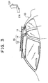
- a crossbar 30 is shown in Fig. 4 in place of the front cross bar 12 or the rear crossbar 14.
- a shape of an upper surface 18' and a lower surface 20' which includes a flow compression face 22', a flow leading face 24', and a flow separation portion 26' have a bit different shapes from the respective shapes of the front crossbar 12 or the rear crossbar 14.
- Such a crossbar 30 of the second embodiment is also available.
- a plane slanting from the upper and the front to the lower and the rear of the crossbar 30 (shown as double-dashed line 22'' in Fig. 4) is also available in the place of the hollowed face as the flow compression face 22'.
- the structure for reducing wind noise of the invention is not limited on a crossbar of a roof rack, and it can also be adopted for a structure for reducing wind for a roof spoiler provided on a roof of a vehicle or for other parts.
Landscapes
- Engineering & Computer Science (AREA)
- Mechanical Engineering (AREA)
- Fittings On The Vehicle Exterior For Carrying Loads, And Devices For Holding Or Mounting Articles (AREA)
- Body Structure For Vehicles (AREA)
- Air-Conditioning For Vehicles (AREA)
Abstract
Description
Claims (17)
- A structure (12, 14, 30) for reducing wind noise provided above a roof (11) along the width of a vehicle,
characterized in that said structure (12, 14, 30) comprises:an upper surface (18, 18') of said structure (12, 14, 30), said upper surface (18, 18') introducing an attached flow of air from the front of the vehicle to the vehicle to the rear of the vehicle; anda lower surface (20, 20') of said structure (12, 14, 30), said lower surface comprising;a flow compression face (22, 22', 22'') in the front of said lower surface (20, 20') for introducing and compressing the air flow from the front of the veihicle,a flow leading face (24, 24') in the center of said lower surface (20, 20') for leading the air flow compressed from the front of said structure (12, 14, 30) to the rear of said structure (12, 14, 30), anda flow separation portion (26, 26') in the rear of said lower surface (20, 20') for separating the air flow from the front of said structure (12, 14, 30). - The structure (12, 14, 30) for reducing wind noise according to claim 1, characterized in that said flow compression face (22, 22') is hollowed toward the center point (12A, 14A, 30A) of the cross-section of said structure (12, 14, 30).
- The structure (30) for reducing wind noise according to claim 1, characterized in that said flow compression face (22'') is a plane slanting from the upper and the front to the lower and rear of said structure (30).
- The structure (12, 14, 30) for reducing wind noise according to claim 1, characterized in that said flow leading face (24, 24') is a smooth convex arc of a circle as the cross-section.
- The structure (12, 14, 30) for reducing wind noise according to claim 1, characterized in that said flow separation portion (26, 26') is notch shaped like a step.
- The structure (12, 14, 30) for reducing wind noise according to claim 1, characterized in that said flow compression face (22, 22') is hollowed toward the center point (12A, 14A, 30A) of the cross-section of said structure (12, 14, 30), said flow leading face (24, 24') is a smooth convex arc of a circle as the cross-section, and said flow separation portion (26, 26') is notch shaped like a step.
- The structure (30) for reducing wind noise according to claim 1, characterized in that said flow compression face (22'') is a plane slanting from the upper and the front to the lower and rear of said structure (30), said flow leading face (24') is a smooth convex arc of a circle as the cross-section, and said flow separation portion (26') is notch shaped like a step.
- The structure (12, 14, 30) for reducing wind noise according to claim 1, characterized in that the most front portion (12B, 148, 30B) of said structure (12, 14, 30) is higher than the horizontal center line (12C, 14C, 30C) of the cross-section of said structure (12, 14, 30).
- The structure (12, 14, 30) for reducing wind noise according to claim 6, characterized in that the most front portion (12B, 14B, 30B) of said structure (12, 14, 30) is higher than the horizontal center line (12C, 14C, 30C) of the cross-section of said structure (12, 14, 30).
- The structure (30) for reducing wind noise according to claim 7, characterized in that the most front portion (30B) of said structure (30) is higher than the horizontal center line (30C) of the cross-section of said structure (30).
- The structure (12, 14, 30) for reducing wind noise according to claim 1, characterized in that said upper surface (18, 18') of said structure (12, 14, 30) is smoothly curved and convex toward the upper direction.
- The structure (12, 14, 30) for reducing wind noise according to claim 6, characterized in that said upper surface (18, 18') of said structure (12, 14, 30) is smoothly curved and convex toward the upper direction.
- The structure (30) for reducing wind noise according to claim 7, characterized in that said upper surface (18') of said structure (30) is smoothly curved and convex toward the upper direction.
- The structure (12, 14, 30) for reducing wind noise according to claim 1, characterized in that in the center part of the width of said structure (12, 14, 30) along the width of the vehicle, the vertical center line (12D, 14D, 30D) connecting the middle point (18A, 18A') on said upper surface (18, 18') from the view point of the front-rear direction with the center point (12A, 14A, 30A) of the cross-section of said structure (12, 14, 30) coincides or substantially coincides with the normal line (L1, L2, L3) of the roof (11) of the vehicle.
- The structure (12, 14, 30) for reducing wind noise according to claim 6, characterized in that in the center part of the width of said structure (12, 14, 30) along the width of the vehicle, the vertical center line (12D, 14D, 30D) connecting the middle point (18A, 18A') on said upper surface (18, 18') from the view point of the front-rear direction with the center point (12A, 14A, 30A) of the cross-section of said structure (12, 14, 30) coincides or substantially coincides with the normal line (L1, L2, L3) of the roof (11) of the vehicle.
- The structure (30) for reducing wind noise according to claim 7, characterized in that in the center part of the width of said structure (30) along the width of the vehicle, the vertical center line (30D) connecting the middle point (18A') on said upper surface (18') from the view point of the front-rear direction with the center point (30A) of the cross-section of said structure (30) coincides or substantially coincides with the normal line (L3) of the roof (11) of the vehicle.
- A vehicle comprising the structure (12, 14, 30) for reducing wind noise according to claim 1 installed along the width direction of the vehicle above the vehicle.
Applications Claiming Priority (2)
| Application Number | Priority Date | Filing Date | Title |
|---|---|---|---|
| JP23965199 | 1999-08-26 | ||
| JP23965199A JP3601367B2 (en) | 1999-08-26 | 1999-08-26 | Wind noise reduction structure |
Publications (3)
| Publication Number | Publication Date |
|---|---|
| EP1078819A2 true EP1078819A2 (en) | 2001-02-28 |
| EP1078819A3 EP1078819A3 (en) | 2001-12-05 |
| EP1078819B1 EP1078819B1 (en) | 2007-05-02 |
Family
ID=17047883
Family Applications (1)
| Application Number | Title | Priority Date | Filing Date |
|---|---|---|---|
| EP00111273A Expired - Lifetime EP1078819B1 (en) | 1999-08-26 | 2000-05-25 | Structure for reducing wind noise |
Country Status (4)
| Country | Link |
|---|---|
| US (1) | US6276747B1 (en) |
| EP (1) | EP1078819B1 (en) |
| JP (1) | JP3601367B2 (en) |
| DE (1) | DE60034633T2 (en) |
Cited By (6)
| Publication number | Priority date | Publication date | Assignee | Title |
|---|---|---|---|---|
| CN101670808A (en) * | 2008-09-09 | 2010-03-17 | 起亚自动车株式会社 | Roof side bar for prevention of noise for automobile |
| WO2016201416A1 (en) * | 2015-06-11 | 2016-12-15 | Cequent Performance Products Inc. | Roof rack crossbar assembly |
| CN108473097A (en) * | 2015-06-09 | 2018-08-31 | 雅捷马产品公司 | Slotted cross bar |
| CN111703383A (en) * | 2020-06-30 | 2020-09-25 | 宁波吉利汽车研究开发有限公司 | Vortex absorbing structure and vehicle for eliminating wind vibration |
| DE102006046814B4 (en) * | 2006-10-02 | 2020-11-12 | Audi Ag | Underbody paneling for a motor vehicle |
| USD947097S1 (en) * | 2019-10-02 | 2022-03-29 | Rhino Rack Australia Pty Limited | Underbar for roof rack with aperture/window |
Families Citing this family (15)
| Publication number | Priority date | Publication date | Assignee | Title |
|---|---|---|---|---|
| JP3771772B2 (en) * | 2000-04-10 | 2006-04-26 | 株式会社東海理化電機製作所 | housing |
| KR20030082809A (en) * | 2002-04-18 | 2003-10-23 | 기아자동차주식회사 | Roof-Lack for Vehicles |
| US6761295B2 (en) | 2002-06-25 | 2004-07-13 | Daimlerchrysler Corporation | Roofrack crossrail assembly cap |
| US20060290154A1 (en) * | 2005-06-24 | 2006-12-28 | Magna International Inc. | One piece long glass fiber molded cross rail with integrated end stanchions |
| JP4847238B2 (en) * | 2006-07-18 | 2011-12-28 | 株式会社ベクタークラフト | Roof carrier |
| NZ561809A (en) | 2007-09-21 | 2009-11-27 | Hubco Automotive Ltd | Resilient infill |
| NZ561811A (en) | 2007-09-21 | 2010-06-25 | Hubco Automotive Ltd | Extendable roof rack |
| NZ561860A (en) * | 2007-09-24 | 2010-04-30 | Hubco Automotive Ltd | Versatile leg for a roof rack |
| NZ571287A (en) * | 2008-09-15 | 2011-03-31 | Hubco Automotive Ltd | A bracket and a crossbar assembly for a roof rack |
| US9187047B2 (en) | 2012-04-30 | 2015-11-17 | Yakima Products, Inc. | Retention dock |
| WO2014022435A1 (en) * | 2012-07-30 | 2014-02-06 | Yakima Innovation Development Corporation | Crossbar t-slot infill |
| EP3031669B1 (en) * | 2014-12-12 | 2018-01-31 | Thule Sweden AB | A roof rack kit and a load strip for a load carrying bar |
| ES1141657Y (en) * | 2015-06-19 | 2015-10-14 | Fed Signal Vama Sa | PRIORITY SENALIZATION BRIDGE WITH VORTICE GENERATORS |
| KR101661348B1 (en) * | 2015-08-12 | 2016-09-29 | 주식회사 케이에이치테크 | Roof rack assembly for mounting roof box of roof panel contact of vehicle |
| US20180086276A1 (en) * | 2016-09-29 | 2018-03-29 | Mobis Parts America Llc | Vehicular roof rack with noise reducing crossbar profile |
Family Cites Families (12)
| Publication number | Priority date | Publication date | Assignee | Title |
|---|---|---|---|---|
| DE2737638A1 (en) * | 1977-08-20 | 1979-03-01 | Volkswagenwerk Ag | VEHICLE TAIL |
| CA1183819A (en) * | 1980-07-23 | 1985-03-12 | John A. Bott | Cross rail for vehicle luggage carrier |
| US4743057A (en) * | 1987-05-11 | 1988-05-10 | Michael Ladney | Spoiler construction and method |
| US5240536A (en) * | 1989-12-16 | 1993-08-31 | Sakae Riken Kogyo Co., Ltd. | Method for manufacturing hollow air spoiler |
| DE4035729C2 (en) * | 1990-11-09 | 1994-06-23 | Bayerische Motoren Werke Ag | Roof racks for vehicles |
| WO1992012874A1 (en) * | 1991-01-16 | 1992-08-06 | Goodcart Pty Limited | Vehicle roof rack |
| US5282560A (en) * | 1993-04-26 | 1994-02-01 | Ford Motor Company | Luggage rack with wind noise reducer |
| US5474218A (en) * | 1994-07-25 | 1995-12-12 | Chrysler Corporation | Article carrier |
| JP3397518B2 (en) * | 1995-06-15 | 2003-04-14 | ダイハツ工業株式会社 | Roof spoiler |
| JP3394393B2 (en) * | 1996-08-05 | 2003-04-07 | トヨタ車体株式会社 | Roof spoiler |
| JPH10278855A (en) | 1997-04-08 | 1998-10-20 | Daihatsu Motor Co Ltd | Rear spoiler device |
| AU3631499A (en) * | 1998-04-22 | 1999-11-08 | Hubco Industries Limited | Roof rack or load carrier |
-
1999
- 1999-08-26 JP JP23965199A patent/JP3601367B2/en not_active Expired - Fee Related
-
2000
- 2000-05-25 EP EP00111273A patent/EP1078819B1/en not_active Expired - Lifetime
- 2000-05-25 DE DE60034633T patent/DE60034633T2/en not_active Expired - Lifetime
- 2000-06-02 US US09/585,574 patent/US6276747B1/en not_active Expired - Fee Related
Cited By (8)
| Publication number | Priority date | Publication date | Assignee | Title |
|---|---|---|---|---|
| DE102006046814B4 (en) * | 2006-10-02 | 2020-11-12 | Audi Ag | Underbody paneling for a motor vehicle |
| CN101670808A (en) * | 2008-09-09 | 2010-03-17 | 起亚自动车株式会社 | Roof side bar for prevention of noise for automobile |
| CN101670808B (en) * | 2008-09-09 | 2013-11-27 | 起亚自动车株式会社 | Roof side bar for prevention of noise for automobile |
| CN108473097A (en) * | 2015-06-09 | 2018-08-31 | 雅捷马产品公司 | Slotted cross bar |
| CN108473097B (en) * | 2015-06-09 | 2021-12-24 | 雅捷马产品公司 | Slotted crossbar |
| WO2016201416A1 (en) * | 2015-06-11 | 2016-12-15 | Cequent Performance Products Inc. | Roof rack crossbar assembly |
| USD947097S1 (en) * | 2019-10-02 | 2022-03-29 | Rhino Rack Australia Pty Limited | Underbar for roof rack with aperture/window |
| CN111703383A (en) * | 2020-06-30 | 2020-09-25 | 宁波吉利汽车研究开发有限公司 | Vortex absorbing structure and vehicle for eliminating wind vibration |
Also Published As
| Publication number | Publication date |
|---|---|
| EP1078819A3 (en) | 2001-12-05 |
| EP1078819B1 (en) | 2007-05-02 |
| US6276747B1 (en) | 2001-08-21 |
| DE60034633T2 (en) | 2007-12-27 |
| DE60034633D1 (en) | 2007-06-14 |
| JP3601367B2 (en) | 2004-12-15 |
| JP2001063479A (en) | 2001-03-13 |
Similar Documents
| Publication | Publication Date | Title |
|---|---|---|
| EP1078819A2 (en) | Structure for reducing wind noise | |
| EP1897787A1 (en) | Car body frame member | |
| US6796604B2 (en) | Front-end panel | |
| US6926344B2 (en) | Pleat or corrugation of a bellows of a connection between two hinge-linked vehicles or vehicle sections e.g., of an articulated bus | |
| US7338099B2 (en) | Bumper beam structure having support walls for center gusset, which are laid over walls of bumper beam | |
| US20240075859A1 (en) | Seatback | |
| JP4013474B2 (en) | Body structure | |
| CN1273927A (en) | Structure of front portion of car body | |
| CN111688736A (en) | Roof protector, rail vehicle automobile body and rail vehicle | |
| CN219728086U (en) | Lower guard plate assembly and automobile | |
| CN214057196U (en) | Mounting structure of car skylight windshield net | |
| US6015341A (en) | Air flow diverter | |
| CN223931989U (en) | A convenient steel shot screening component | |
| CN214404222U (en) | Novel buckle structure | |
| CN217347447U (en) | Wind screen pressing block structure | |
| CN223520673U (en) | Side assembly structure of light bus seat | |
| CN214450756U (en) | Automobile wire harness fixer | |
| CN218368081U (en) | Motorcycle cushion hump assembly and motorcycle | |
| KR102869096B1 (en) | Roof structure for vehicle | |
| CN210174979U (en) | Beam and ceiling lap joint structure | |
| CN215260442U (en) | Air conditioner casing and air conditioner thereof | |
| CN217864409U (en) | Car guide plate easy to assemble | |
| CN219948369U (en) | Side panel upper joints for vehicles and vehicles | |
| CN212680499U (en) | Dust collector of sound construction | |
| CN217908955U (en) | Installation component and model car |
Legal Events
| Date | Code | Title | Description |
|---|---|---|---|
| PUAI | Public reference made under article 153(3) epc to a published international application that has entered the european phase |
Free format text: ORIGINAL CODE: 0009012 |
|
| 17P | Request for examination filed |
Effective date: 20000525 |
|
| AK | Designated contracting states |
Kind code of ref document: A2 Designated state(s): AT BE CH CY DE DK ES FI FR GB GR IE IT LI LU MC NL PT SE Kind code of ref document: A2 Designated state(s): DE FR GB SE |
|
| AX | Request for extension of the european patent |
Free format text: AL;LT;LV;MK;RO;SI |
|
| PUAL | Search report despatched |
Free format text: ORIGINAL CODE: 0009013 |
|
| AK | Designated contracting states |
Kind code of ref document: A3 Designated state(s): AT BE CH CY DE DK ES FI FR GB GR IE IT LI LU MC NL PT SE |
|
| AX | Request for extension of the european patent |
Free format text: AL;LT;LV;MK;RO;SI |
|
| AKX | Designation fees paid |
Free format text: DE FR GB SE |
|
| 17Q | First examination report despatched |
Effective date: 20030122 |
|
| APBN | Date of receipt of notice of appeal recorded |
Free format text: ORIGINAL CODE: EPIDOSNNOA2E |
|
| APBR | Date of receipt of statement of grounds of appeal recorded |
Free format text: ORIGINAL CODE: EPIDOSNNOA3E |
|
| APAA | Appeal reference recorded |
Free format text: ORIGINAL CODE: EPIDOS REFN |
|
| APAF | Appeal reference modified |
Free format text: ORIGINAL CODE: EPIDOSCREFNE |
|
| APBT | Appeal procedure closed |
Free format text: ORIGINAL CODE: EPIDOSNNOA9E |
|
| GRAP | Despatch of communication of intention to grant a patent |
Free format text: ORIGINAL CODE: EPIDOSNIGR1 |
|
| GRAS | Grant fee paid |
Free format text: ORIGINAL CODE: EPIDOSNIGR3 |
|
| GRAA | (expected) grant |
Free format text: ORIGINAL CODE: 0009210 |
|
| AK | Designated contracting states |
Kind code of ref document: B1 Designated state(s): DE FR GB SE |
|
| REG | Reference to a national code |
Ref country code: SE Ref legal event code: TRGR Ref country code: GB Ref legal event code: FG4D |
|
| RIN1 | Information on inventor provided before grant (corrected) |
Inventor name: OGAWA, ATOMUC/O TOYOTA JIDOSHA KABUSHIKI KAISHA Inventor name: MIZUNO, TOSHIYUKIC/O TOYOTA JIDOSHA KABUSHIKI KAIS |
|
| REF | Corresponds to: |
Ref document number: 60034633 Country of ref document: DE Date of ref document: 20070614 Kind code of ref document: P |
|
| ET | Fr: translation filed | ||
| PLBE | No opposition filed within time limit |
Free format text: ORIGINAL CODE: 0009261 |
|
| STAA | Information on the status of an ep patent application or granted ep patent |
Free format text: STATUS: NO OPPOSITION FILED WITHIN TIME LIMIT |
|
| 26N | No opposition filed |
Effective date: 20080205 |
|
| PGFP | Annual fee paid to national office [announced via postgrant information from national office to epo] |
Ref country code: GB Payment date: 20100329 Year of fee payment: 11 |
|
| PGFP | Annual fee paid to national office [announced via postgrant information from national office to epo] |
Ref country code: FR Payment date: 20100525 Year of fee payment: 11 |
|
| PGFP | Annual fee paid to national office [announced via postgrant information from national office to epo] |
Ref country code: DE Payment date: 20100519 Year of fee payment: 11 |
|
| PGFP | Annual fee paid to national office [announced via postgrant information from national office to epo] |
Ref country code: SE Payment date: 20100510 Year of fee payment: 11 |
|
| REG | Reference to a national code |
Ref country code: DE Ref legal event code: R119 Ref document number: 60034633 Country of ref document: DE |
|
| REG | Reference to a national code |
Ref country code: DE Ref legal event code: R119 Ref document number: 60034633 Country of ref document: DE |
|
| REG | Reference to a national code |
Ref country code: SE Ref legal event code: EUG |
|
| GBPC | Gb: european patent ceased through non-payment of renewal fee |
Effective date: 20110525 |
|
| REG | Reference to a national code |
Ref country code: FR Ref legal event code: ST Effective date: 20120131 |
|
| PG25 | Lapsed in a contracting state [announced via postgrant information from national office to epo] |
Ref country code: FR Free format text: LAPSE BECAUSE OF NON-PAYMENT OF DUE FEES Effective date: 20110531 |
|
| PG25 | Lapsed in a contracting state [announced via postgrant information from national office to epo] |
Ref country code: GB Free format text: LAPSE BECAUSE OF NON-PAYMENT OF DUE FEES Effective date: 20110525 |
|
| PG25 | Lapsed in a contracting state [announced via postgrant information from national office to epo] |
Ref country code: SE Free format text: LAPSE BECAUSE OF NON-PAYMENT OF DUE FEES Effective date: 20110526 |
|
| PG25 | Lapsed in a contracting state [announced via postgrant information from national office to epo] |
Ref country code: DE Free format text: LAPSE BECAUSE OF NON-PAYMENT OF DUE FEES Effective date: 20111130 |