EP1078812A2 - Vehicle occupant protection system - Google Patents
Vehicle occupant protection system Download PDFInfo
- Publication number
- EP1078812A2 EP1078812A2 EP00117955A EP00117955A EP1078812A2 EP 1078812 A2 EP1078812 A2 EP 1078812A2 EP 00117955 A EP00117955 A EP 00117955A EP 00117955 A EP00117955 A EP 00117955A EP 1078812 A2 EP1078812 A2 EP 1078812A2
- Authority
- EP
- European Patent Office
- Prior art keywords
- vehicle
- deceleration
- moveable part
- vehicle body
- vehicle occupant
- Prior art date
- Legal status (The legal status is an assumption and is not a legal conclusion. Google has not performed a legal analysis and makes no representation as to the accuracy of the status listed.)
- Granted
Links
Images



Classifications
-
- B—PERFORMING OPERATIONS; TRANSPORTING
- B60—VEHICLES IN GENERAL
- B60R—VEHICLES, VEHICLE FITTINGS, OR VEHICLE PARTS, NOT OTHERWISE PROVIDED FOR
- B60R22/00—Safety belts or body harnesses in vehicles
- B60R22/18—Anchoring devices
- B60R22/195—Anchoring devices with means to tension the belt in an emergency, e.g. means of the through-anchor or splitted reel type
- B60R22/1951—Anchoring devices with means to tension the belt in an emergency, e.g. means of the through-anchor or splitted reel type characterised by arrangements in vehicle or relative to seat belt
Definitions
- the present invention relates to a vehicle occupant protection system for improving the vehicle crash safety.
- the deceleration of the vehicle occupant is produced by the force applied from a restraint system such as a seat belt. Because a seat belt functions as a spring, the maximum value of the deceleration of the vehicle occupant occurs when the elongation of the seat belt is maximized as the vehicle occupant moves forward under the inertia force. The maximum value of the deceleration of the vehicle occupant increases in relation with the increase in the forward travel of the vehicle occupant under the inertia force, and may even exceed the average deceleration of the vehicle body.
- a crushable zone formed at a front portion of the vehicle body between a crash reaction generating member (such as side beams) and other components is allowed to deform so as to absorb the impact energy, and the waveform of the vehicle body deceleration is adjusted by changing the reaction property through appropriate selection of dimensions of various parts.
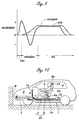
- Figure 9 shows a waveform of the deceleration of the seat belt that would favorably control the vehicle occupant deceleration according to the foregoing considerations.
- a deceleration which is greater than the average deceleration of the vehicle body is initially produced for a prescribed (short) time period, and then, a deceleration in the opposite direction is produced for another prescribed (short) time period. Thereafter, the seat is allowed to decelerate at the average deceleration.
- a primary object of the present invention is to provide a vehicle occupant protection system which can favorably reduce the vehicle occupant deceleration at the time of a vehicle crash by using a highly simple structure.
- a second object of the present invention is to provide a vehicle occupant protection system which is adapted to the standard design of the seat belt and the vehicle body.
- a third object of the present invention is to provide a vehicle occupant protection system which would not substantially increase the weight of the vehicle body.
- an automotive vehicle occupant protection system comprising: a moveable part of a vehicle body including a vehicle seat and moveable in a fore-and-aft direction with respect to a vehicle body; a power source which is adapted to apply a rearward force to the moveable part in an early phase of a vehicle crash, and a forward force to the moveable part immediately following the early phase; a seat belt for the seat having a first anchor point which is attached to the moveable part, and a second anchor point which is attached to a fixed part of the vehicle body.
- the seat belt is pulled rearward, and performs the function to apply a deceleration to the vehicle occupant in an early phase of the vehicle crash. This is followed by a slight slackening of the seat belt as the moveable part is subjected to a forward force.
- an early application of a forward deceleration followed by the application of an acceleration which tends to mitigate the unacceptable sharp rise of the deceleration of the vehicle occupant achieves a desirable time history of deceleration for the vehicle occupant, and minimizes the injury to the vehicle occupant for a given stroke of deformation of the vehicle body.
- the power source may consist of an active power actuator such as a high pressure gas generating device for applying a rearward force and/or forward force to the moveable part.
- the power source may comprise an impact transmitting member such as a G control member which forms a part of the moveable part, and is adapted to apply a rearward force to the moveable part as the impact transmitting member receives an impact from a vehicle crash.
- the power source may comprise a stopper member which is interposed between the moveable part and a fixed part of the vehicle body, the stopper being adapted to collide with the moveable part as the moveable part moves rearward with respect to the vehicle body under the rearward force.
- the first anchor point consists of a seat belt buckle
- the second anchor point consists of a shoulder anchor of the seat belt.
- the anchor points may include a third anchor point which may be attached either to the moveable part or to a fixed part of the vehicle body.
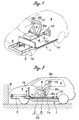
- FIG. 1 is a perspective view showing an essential part of an automotive vehicle body embodying the present invention.
- a seat base frame 2 is placed on a vehicle body 1 so as to be moveable in the fore-and-aft direction of the vehicle body.
- the seat base frame 2 is simplified as a rod-like member, but in practice may consist of any frame structure or member.
- the vehicle body 1 comprises a floor section 1a of a passenger compartment 4 which is integrally attached to an upper surface of a pair of side beams 3 extending from the front end to the rear end of the vehicle body on either side of the vehicle body to serve as major energy absorbing members, and a bulkhead section 1b extending upward from the front edge of the floor section 1a to the lower edge of the front windshield at the boundary between the passenger compartment 4 and an engine room 5.
- the seat base frame 2 extends in the fore-and-aft direction in parallel with the floor section 1a of the vehicle body 1.
- the front end of the seat base frame 2 is provided with a power actuator 6 consisting of a high pressure gas generating device, and the rear end of the seat base frame 2 is provided with a damping device 10 which consists of a passive stopper as described hereinafter.
- a seat 8 is mounted on the seat base frame 2, and may be provided with a seat slide adjustment arrangement disposed between the seat 8 and the seat base frame 2 although it is not shown in the drawings because the arrangement by itself is convention, and the structure thereof forms no part of the present invention.
- the seat base frame 2 and the seat 8 jointly form a moveable part 20 which is normally integral with the vehicle body 1, but can move in the fore-and-aft direction relative to the vehicle body 1 at the time of a vehicle crash as described hereinafter.
- the seat 8 is provided with a seat belt 9 which has three anchor points.
- a seat belt buckle 9a fixedly attached to a side of the seat 8 forms a first anchor point
- a shoulder anchor 9b fixedly attached to an upper part of a center pillar 15 forms a second anchor point.
- a waist belt anchor 9c ( Figure 4) which is fixedly attached to a lower part of the center pillar 15 or a vehicle body part adjacent thereto at the end of the waist belt remote from the seat belt buckle 9a forms a third anchor point.
- the waist belt anchor 9c may also be attached to the corresponding side of the seat 8.
- the seat belt 8 is by itself conventional, and is provided with a tongue plate which is fitted to an intermediate part of the seat belt 9, and is adapted to latch into the seat belt buckle 9a.
- the front end of the seat base frame 2 is provided with a rod portion 2a which is received in a cylinder 11 of the high pressure gas generating device 6.
- This cylinder 11 is fixedly attached to the vehicle body 1.
- a propellant 12 for generating high pressure gas is received deep inside the cylinder 11, and is adapted to be ignited by an ignition device 13 upon detection of a vehicle crash by a sensor not shown in the drawings.
- the high pressure gas produced from the propellant 12 applies a thrust to the rod portion 2a of the seat base frame 2, and thereby gives a rearward acceleration to the moveable part 20.
- the rear end of the seat base frame 2 is adapted to be engaged by the damping device 10 following a prescribed rearward travel of the seat base frame 2 relative to the vehicle body 1.
- the damping device 10 may, for instance, consist of a stopper consisting of a honeycomb structure which abuts the rear end of the seat base frame 2 as the latter moves rearward by a prescribed distance relative to the vehicle body 1, and the resultant reaction produces an opposite deceleration or a forward acceleration that will be applied to the seat base frame 2 and the vehicle seat 8.
- the vehicle occupant is restrained by the seat belt 9 which is anchored to the center pillar 15 at two points (9b and 9c), and to the seat 8 or the moveable part 20 at one point (9a).
- the vehicle occupant is subjected to a forward inertia force at the time of a vehicle crash, and is restrained mainly by the seat belt 9. Otherwise, the vehicle occupant would be thrown forward relative to the vehicle body 1.
- the vehicle occupant can be subjected to a controlled forward deceleration at such a time primarily owing to the restraint by the seat belt 9, and the level of the forward deceleration can be controlled most effectively by adjusting the tension of the seat belt 9. For instance, if the seat belt buckle 9a is moved rearward with respect to the vehicle body as indicated by arrow F, the deceleration acting on the vehicle occupant will be increased, and vice versa.
- the seat belt buckle 9a is displaced rearward, along with the seat base frame 2, in the early phase of the vehicle crash while the remaining anchor points 9b and 9c remain stationary with respect to the vehicle body 1. Therefore, as seen from the vehicle body, one of the anchor points (9a) of the seat belt 9 is moved rearward, and the seat belt 9 is thereby made effective in restraining the vehicle occupant from a relatively early time point of the vehicle crash. It means that the vehicle occupant is allowed to experience the forward deceleration from an early phase of the vehicle crash, and this is beneficial in optimizing the time history of the deceleration of the vehicle occupant as discusses earlier.
- a passenger automobile is typically fitted with a pair of seats 8 on either side.
- the two seats 8 may be mounted on separate seat base frame 2 each connected to an associated power actuator 6 and/or damping device 10.
- the two seats 8 may be joined integrally to a common seat base frame.
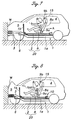
- a passive damping device 10 was used in this embodiment for applying a forward acceleration to the moveable part 20 in the above described embodiment, but it is also possible to use, instead, a high pressure gas generating device similar to that for the power actuator 6 of the first embodiment.
- a high pressure gas generating device similar to that for the power actuator 6 of the first embodiment.
- An active power actuator 16 similar to the power actuator 6 is provided at the rear end of the seat base frame 2 to serve a similar purpose as the damping device 10.
- This embodiment is otherwise similar to the previous embodiment, and the corresponding parts are denoted with like numerals.
- the embodiment illustrated in Figure 11 relies entirely on passive devices for applying both forward and rearward accelerations at the time of a vehicle crash.
- This embodiment comprises an impact transmitting member in the form of a pair of G control frames 17 extending from the front end of the seat base frame 2, through the bulkhead section 1b of the vehicle body 1.
- a damping device 10 similar to that for the first embodiment is provided on a part of the floor section 1b adjacent to the rear end of the seat base frame 2. According to this embodiment, when the vehicle crashes head-on onto an object, the side beams 3 collapse before the G control frames 17 do, and the impact of the crash is transmitted to the seat base frame 2 or the moveable part 20 from a relatively early phase of the crash.
- the damping device 10 applies a forward acceleration to the seat base frame 2 following a prescribed rearward displacement of the moveable part 20 relative to the vehicle body 1 or a certain time delay, and the seat base frame 2 is thereafter allowed to move or collapse integrally with the remaining part of the vehicle body.
- At least one seat belt anchor is provided in a moveable part which is moveable in the fore-and-aft direction relative to the vehicle body, and the moveable part is positively moved in the rearward direction in an early stage of a vehicle crash.
- the vehicle occupant is thus subjected to a deceleration greater than an average deceleration in an early stage of a vehicle crash through an increased tension of the seat belt, and, thereafter, a forward acceleration is temporarily produced in the moveable part through slight slackening of the seat belt before the entire vehicle body finally decelerates at the average deceleration.
- the optimum time history of deceleration for the vehicle occupant can be achieved, and the vehicle occupant is allowed to decelerate without experiencing any intolerable peaks in the deceleration level.
- the normal seat and seat belt can be used, instead of a seat incorporated with a seat belt, this arrangement can be readily adapted to a wide range of applications.
- the seat belt which is anchored at the moveable part at one end and a fixed part of the vehicle body at another end is pulled rearward, and performs the function to apply a deceleration to the vehicle occupant in an early phase of the vehicle crash. This is followed by a slight slackening of the seat belt as the moveable part is subjected to a forward force.
- the active power source typically consists of a high pressure gas generating device
- a passive power source typically consists of a G control member which transmits the deceleration of a vehicle crash to the vehicle occupant from an early phase of the crash, and/or a stopper which applies a forward force to the moveable part as the moveable part moves rearward by a prescribed distance under the action of the power source.
Landscapes
- Engineering & Computer Science (AREA)
- Mechanical Engineering (AREA)
- Automotive Seat Belt Assembly (AREA)
- Body Structure For Vehicles (AREA)
- Seats For Vehicles (AREA)
Abstract
Description
Claims (6)
- An automotive vehicle occupant protection system, comprising:a moveable part of a vehicle body including a vehicle seat and moveable in a fore-and-aft direction with respect to a vehicle body;a power source which is adapted to apply a rearward force to said moveable part in an early phase of a vehicle crash, and a forward force to said moveable part immediately following said early phase;a seat belt for said seat having a first anchor point which is attached to said moveable part, and a second anchor point which is attached to a fixed part of said vehicle body.
- An automotive vehicle occupant protection system according to claim 1, wherein said power source comprises a power actuator for applying a rearward force to said moveable part.
- An automotive vehicle occupant protection system according to claim 1, wherein said power source comprises a power actuator for applying a forward force to said moveable part.
- An automotive vehicle occupant protection system according to claim 1, wherein said power source comprises an impact transmitting member which forms a part of said moveable part, and is adapted to apply a rearward force to said moveable part as said impact transmitting member receives an impact from a vehicle crash.
- An automotive vehicle occupant protection system according to claim 1, wherein said power source comprises a stopper member which is interposed between said moveable part and a fixed part of said vehicle body, said stopper being adapted to collide with said moveable part as said moveable part moves rearward with respect to the vehicle body under said rearward force.
- An automotive vehicle occupant protection system according to claim 1, wherein said first anchor point consists of a seat belt buckle, and said second anchor point consists of a shoulder anchor of said seat belt.
Applications Claiming Priority (2)
| Application Number | Priority Date | Filing Date | Title |
|---|---|---|---|
| JP23628299 | 1999-08-24 | ||
| JP23628299 | 1999-08-24 |
Publications (3)
| Publication Number | Publication Date |
|---|---|
| EP1078812A2 true EP1078812A2 (en) | 2001-02-28 |
| EP1078812A3 EP1078812A3 (en) | 2002-05-08 |
| EP1078812B1 EP1078812B1 (en) | 2004-04-21 |
Family
ID=16998486
Family Applications (1)
| Application Number | Title | Priority Date | Filing Date |
|---|---|---|---|
| EP00117955A Expired - Lifetime EP1078812B1 (en) | 1999-08-24 | 2000-08-21 | Vehicle occupant protection system |
Country Status (3)
| Country | Link |
|---|---|
| US (1) | US6422632B1 (en) |
| EP (1) | EP1078812B1 (en) |
| DE (1) | DE60009995T2 (en) |
Cited By (1)
| Publication number | Priority date | Publication date | Assignee | Title |
|---|---|---|---|---|
| WO2006089930A1 (en) * | 2005-02-23 | 2006-08-31 | Heinz Peter | Protective system for increasing passenger safety in a motor vehicle |
Families Citing this family (15)
| Publication number | Priority date | Publication date | Assignee | Title |
|---|---|---|---|---|
| SE514294C2 (en) * | 1998-09-30 | 2001-02-05 | Volvo Lastvagnar Ab | Device enabling displacement of the driver's compartment of a vehicle |
| JP3904384B2 (en) * | 2000-10-31 | 2007-04-11 | 本田技研工業株式会社 | Crew protection device |
| JP4350921B2 (en) | 2001-06-12 | 2009-10-28 | 本田技研工業株式会社 | Crew protection device |
| JP4621384B2 (en) * | 2001-07-18 | 2011-01-26 | 本田技研工業株式会社 | Crew protection device |
| JP4448626B2 (en) * | 2001-07-18 | 2010-04-14 | 本田技研工業株式会社 | Crew protection device |
| US6655729B2 (en) * | 2001-09-13 | 2003-12-02 | Intier Automotive Inc. | Bridge assembly |
| JP2003089335A (en) * | 2001-09-18 | 2003-03-25 | Honda Motor Co Ltd | Occupant protection device |
| US20060220426A1 (en) * | 2005-04-05 | 2006-10-05 | Edward Moffatt | Rollover deployed reclining seatback |
| JP5182843B2 (en) * | 2007-02-15 | 2013-04-17 | テイ・エス テック株式会社 | Vehicle seat |
| US20100001568A1 (en) * | 2008-07-03 | 2010-01-07 | Dalton Trybus | Vehicle seat with cushion carrier |
| DE102010062550A1 (en) * | 2009-12-09 | 2011-09-01 | Tk Holdings, Inc. | Occupant safety system |
| US9132751B2 (en) * | 2012-07-26 | 2015-09-15 | Leggett & Platt Canada Co. | Remote damping system |
| US9352783B2 (en) | 2014-04-17 | 2016-05-31 | Tesla Motors, Inc. | Vehicle crush rail with substantially square cells and initiators |
| US11400839B2 (en) * | 2020-09-22 | 2022-08-02 | Ford Global Technologies, Llc | Energy absorbing vehicle seat |
| US12594863B1 (en) * | 2025-07-21 | 2026-04-07 | Automotive Safety Research, Inc. | System for mitigating the severity of motor vehicle crashes |
Family Cites Families (43)
| Publication number | Priority date | Publication date | Assignee | Title |
|---|---|---|---|---|
| US3001815A (en) | 1958-02-25 | 1961-09-26 | Robert C Weber | Bumper actuated vehicle safety seat |
| US2959446A (en) | 1958-04-24 | 1960-11-08 | Thompson William Francis | Automobile crash absorbing construction |
| GB1043695A (en) | 1962-09-19 | 1966-09-21 | Nat Res Dev | Improvements in or relating to safety harness and like safety devices for occupants of vehicles |
| US3732944A (en) | 1971-04-12 | 1973-05-15 | Menasco Mfg Co | Automatic vacuum restraint apparatus |
| US3897101A (en) | 1973-05-18 | 1975-07-29 | Brose & Co Metallwerk Max | Driver{3 s seat with inertia-responsive locking arrangement |
| DE2344689A1 (en) * | 1973-09-05 | 1975-03-13 | Porsche Ag | SAFETY DEVICE FOR MOTOR VEHICLES |
| DE2416313C3 (en) * | 1974-04-04 | 1978-11-23 | Roland 8731 Euerdorf Satzinger | Safety device for the occupants of vehicles, in particular motor vehicles |
| US3998291A (en) | 1975-08-06 | 1976-12-21 | Edwin George Davis | Automotive safety seat |
| CH612503A5 (en) | 1977-05-13 | 1979-07-31 | Mettler Instrumente Ag | |
| DE3424928A1 (en) | 1984-07-06 | 1986-01-16 | Walter 8720 Schweinfurt Lindwurm | Catapult seat safety system for motor vehicles |
| US4832409A (en) | 1987-09-08 | 1989-05-23 | General Motors Corporation | Restraint belt load capacity fore and aft power seat adjuster apparatus |
| US4881781A (en) | 1987-09-08 | 1989-11-21 | General Motors Corporation | Restraint belt load capacity fore and aft power seat adjuster apparatus and method |
| DE3801347A1 (en) * | 1988-01-19 | 1989-07-27 | Audi Ag | ARRANGEMENT OF A FRONT DRIVE UNIT IN A MOTOR VEHICLE |
| US5286085A (en) | 1989-06-30 | 1994-02-15 | Takata Corporation | Restraining protective seat for infants |
| US5167421A (en) | 1990-07-16 | 1992-12-01 | Liu Yunzhao | Safety seat equipped in automobile |
| JP2770563B2 (en) * | 1990-09-18 | 1998-07-02 | 日産自動車株式会社 | Vehicle occupant protection device |
| DE4032385C2 (en) * | 1990-10-12 | 1994-06-23 | Audi Ag | Safety device for a vehicle occupant |
| AU2460192A (en) | 1991-07-19 | 1993-02-23 | Massachusetts Institute Of Technology | Safety seat |
| JP3327297B2 (en) | 1992-02-26 | 2002-09-24 | マツダ株式会社 | Vehicle impact control structure and impact control method |
| JPH05246252A (en) | 1992-03-04 | 1993-09-24 | Toyota Motor Corp | Battery fixing structure for electric vehicles |
| JP2866998B2 (en) | 1992-03-04 | 1999-03-08 | トヨタ自動車株式会社 | Battery fixing structure for electric vehicles |
| US5437494A (en) | 1992-10-29 | 1995-08-01 | Life Force Associates, L.P. | Rearward moving seat |
| DE4345185C2 (en) | 1993-03-31 | 1995-03-23 | Mueller Franz Dipl Ing Fh | Method for reducing the forces acting on a seat belted vehicle occupant in the event of a vehicle colliding with an obstacle using airbags |
| US5409262A (en) | 1993-08-31 | 1995-04-25 | Mclennan; Ronald A. | Vehicle safety system |
| JPH07101354A (en) | 1993-10-05 | 1995-04-18 | Isuzu Motors Ltd | Vehicle side member |
| JPH07205733A (en) | 1994-01-20 | 1995-08-08 | Kunihiro Hasegawa | Vehicle safety mechanism |
| US5681057A (en) | 1995-02-17 | 1997-10-28 | U.S. Electricar | Crash energy-management structure |
| US5810417A (en) | 1995-09-28 | 1998-09-22 | Mongkol Jesadanont | Automatic safety car seats and sheet-type safety-belt |
| US5626203A (en) | 1995-11-01 | 1997-05-06 | Habib; Mostafa S. | Active control of a vehicle occupant's body in frontal collision |
| GB9525033D0 (en) | 1995-12-07 | 1996-02-07 | Henlys Group Plc | Safety seat |
| US5685603A (en) | 1996-03-05 | 1997-11-11 | Trw Vehicle Safety Systems Inc. | Apparatus with a child seat and an energy absorption mechanism |
| WO1998040238A1 (en) | 1997-03-11 | 1998-09-17 | Kent Nilsson | Device for avoiding whiplash injuries |
| US5947543A (en) * | 1997-04-03 | 1999-09-07 | Hubbard; Leo James | Vehicle safety system |
| US6092853A (en) * | 1997-04-03 | 2000-07-25 | Hubbard; Leo James | Vehicle safety system |
| US6042190A (en) | 1997-09-19 | 2000-03-28 | Daimlerchrysler Ag | Vehicle seat |
| JP2000062557A (en) | 1998-08-20 | 2000-02-29 | Honda Motor Co Ltd | Occupant protection device |
| JP3459776B2 (en) | 1998-08-20 | 2003-10-27 | 本田技研工業株式会社 | Occupant protection device |
| US6116561A (en) | 1998-08-28 | 2000-09-12 | Lear Corporation | Method and apparatus for seat track construction |
| US6170865B1 (en) | 1999-01-23 | 2001-01-09 | Martin Barron | Electromagnetic car seat release upon deployment of vehicular air bag |
| US6227563B1 (en) | 1999-04-30 | 2001-05-08 | Rueben Talisman | Airbag responsive seat release safety system |
| JP2001039249A (en) | 1999-07-30 | 2001-02-13 | Honda Motor Co Ltd | Car body structure |
| US6224131B1 (en) | 1999-09-21 | 2001-05-01 | Mohammad Shammout | Reactive seat system |
| US6227597B1 (en) | 1999-09-27 | 2001-05-08 | Trw Inc. | Vehicle seat with limited rearward movement |
-
2000
- 2000-08-21 DE DE60009995T patent/DE60009995T2/en not_active Expired - Fee Related
- 2000-08-21 EP EP00117955A patent/EP1078812B1/en not_active Expired - Lifetime
- 2000-08-23 US US09/648,190 patent/US6422632B1/en not_active Expired - Fee Related
Cited By (1)
| Publication number | Priority date | Publication date | Assignee | Title |
|---|---|---|---|---|
| WO2006089930A1 (en) * | 2005-02-23 | 2006-08-31 | Heinz Peter | Protective system for increasing passenger safety in a motor vehicle |
Also Published As
| Publication number | Publication date |
|---|---|
| EP1078812B1 (en) | 2004-04-21 |
| DE60009995D1 (en) | 2004-05-27 |
| US6422632B1 (en) | 2002-07-23 |
| EP1078812A3 (en) | 2002-05-08 |
| DE60009995T2 (en) | 2005-04-28 |
Similar Documents
| Publication | Publication Date | Title |
|---|---|---|
| US6863308B2 (en) | Automotive vehicle occupant protection system | |
| EP1078812B1 (en) | Vehicle occupant protection system | |
| US6398292B2 (en) | Vehicle body structure for improved crash safety | |
| US6186574B1 (en) | Vehicle occupant protection system | |
| EP1067014B1 (en) | Vehicle occupant protection system | |
| US6843504B2 (en) | Automotive vehicle occupant protection system | |
| JP2001163136A (en) | Occupant protection device | |
| EP1203700B1 (en) | Vehicle occupant protection system | |
| EP1266809B1 (en) | Automotive vehicle occupant protection system | |
| US6378929B2 (en) | Occupant protective apparatus | |
| US6851505B2 (en) | Occupant protective apparatus | |
| US6578894B2 (en) | Automotive vehicle occupant protection system | |
| JP2003025939A (en) | Occupant protection device | |
| JP2003026039A (en) | Occupant protection device | |
| JP2001130354A (en) | Occupant protection device | |
| JP2003025889A (en) | Occupant protection device | |
| JP2001163250A (en) | Car body structure | |
| JP2001163138A (en) | Occupant protection device | |
| JP2003306108A (en) | Occupant protection device | |
| JP2001163261A (en) | Occupant protection device | |
| JP2003306126A (en) | Occupant protection device | |
| JP2003306109A (en) | Occupant protection device | |
| JP2001163175A (en) | Occupant protection device | |
| JP2002145014A (en) | Occupant protection device | |
| JP2001163133A (en) | Occupant protection device |
Legal Events
| Date | Code | Title | Description |
|---|---|---|---|
| PUAI | Public reference made under article 153(3) epc to a published international application that has entered the european phase |
Free format text: ORIGINAL CODE: 0009012 |
|
| AK | Designated contracting states |
Kind code of ref document: A2 Designated state(s): AT BE CH CY DE DK ES FI FR GB GR IE IT LI LU MC NL PT SE |
|
| AX | Request for extension of the european patent |
Free format text: AL;LT;LV;MK;RO;SI |
|
| PUAL | Search report despatched |
Free format text: ORIGINAL CODE: 0009013 |
|
| AK | Designated contracting states |
Kind code of ref document: A3 Designated state(s): AT BE CH CY DE DK ES FI FR GB GR IE IT LI LU MC NL PT SE |
|
| AX | Request for extension of the european patent |
Free format text: AL;LT;LV;MK;RO;SI |
|
| 17P | Request for examination filed |
Effective date: 20020704 |
|
| AKX | Designation fees paid |
Designated state(s): DE FR GB |
|
| 17Q | First examination report despatched |
Effective date: 20030117 |
|
| GRAP | Despatch of communication of intention to grant a patent |
Free format text: ORIGINAL CODE: EPIDOSNIGR1 |
|
| GRAP | Despatch of communication of intention to grant a patent |
Free format text: ORIGINAL CODE: EPIDOSNIGR1 |
|
| GRAS | Grant fee paid |
Free format text: ORIGINAL CODE: EPIDOSNIGR3 |
|
| GRAA | (expected) grant |
Free format text: ORIGINAL CODE: 0009210 |
|
| AK | Designated contracting states |
Kind code of ref document: B1 Designated state(s): DE FR GB |
|
| REG | Reference to a national code |
Ref country code: GB Ref legal event code: FG4D |
|
| REG | Reference to a national code |
Ref country code: IE Ref legal event code: FG4D |
|
| REF | Corresponds to: |
Ref document number: 60009995 Country of ref document: DE Date of ref document: 20040527 Kind code of ref document: P |
|
| ET | Fr: translation filed | ||
| PLBE | No opposition filed within time limit |
Free format text: ORIGINAL CODE: 0009261 |
|
| STAA | Information on the status of an ep patent application or granted ep patent |
Free format text: STATUS: NO OPPOSITION FILED WITHIN TIME LIMIT |
|
| 26N | No opposition filed |
Effective date: 20050124 |
|
| REG | Reference to a national code |
Ref country code: IE Ref legal event code: MM4A |
|
| PGFP | Annual fee paid to national office [announced via postgrant information from national office to epo] |
Ref country code: FR Payment date: 20050809 Year of fee payment: 6 |
|
| PGFP | Annual fee paid to national office [announced via postgrant information from national office to epo] |
Ref country code: GB Payment date: 20060816 Year of fee payment: 7 |
|
| PGFP | Annual fee paid to national office [announced via postgrant information from national office to epo] |
Ref country code: DE Payment date: 20060817 Year of fee payment: 7 |
|
| REG | Reference to a national code |
Ref country code: FR Ref legal event code: ST Effective date: 20070430 |
|
| GBPC | Gb: european patent ceased through non-payment of renewal fee |
Effective date: 20070821 |
|
| PG25 | Lapsed in a contracting state [announced via postgrant information from national office to epo] |
Ref country code: FR Free format text: LAPSE BECAUSE OF NON-PAYMENT OF DUE FEES Effective date: 20060831 |
|
| PG25 | Lapsed in a contracting state [announced via postgrant information from national office to epo] |
Ref country code: DE Free format text: LAPSE BECAUSE OF NON-PAYMENT OF DUE FEES Effective date: 20080301 |
|
| PG25 | Lapsed in a contracting state [announced via postgrant information from national office to epo] |
Ref country code: GB Free format text: LAPSE BECAUSE OF NON-PAYMENT OF DUE FEES Effective date: 20070821 |