EP1078758A2 - Substrate unit for liquid discharging head, method for producting the same, liquid discharging head, cartridge, and image forming apparatus - Google Patents
Substrate unit for liquid discharging head, method for producting the same, liquid discharging head, cartridge, and image forming apparatus Download PDFInfo
- Publication number
- EP1078758A2 EP1078758A2 EP00118081A EP00118081A EP1078758A2 EP 1078758 A2 EP1078758 A2 EP 1078758A2 EP 00118081 A EP00118081 A EP 00118081A EP 00118081 A EP00118081 A EP 00118081A EP 1078758 A2 EP1078758 A2 EP 1078758A2
- Authority
- EP
- European Patent Office
- Prior art keywords
- protective layer
- discharging head
- liquid discharging
- liquid
- covered
- Prior art date
- Legal status (The legal status is an assumption and is not a legal conclusion. Google has not performed a legal analysis and makes no representation as to the accuracy of the status listed.)
- Granted
Links
- 239000000758 substrate Substances 0.000 title claims abstract description 140
- 239000007788 liquid Substances 0.000 title claims abstract description 116
- 238000007599 discharging Methods 0.000 title claims abstract description 74
- 238000000034 method Methods 0.000 title description 36
- 239000011241 protective layer Substances 0.000 claims abstract description 244
- 238000009835 boiling Methods 0.000 claims abstract description 13
- 238000004519 manufacturing process Methods 0.000 claims abstract description 8
- 238000007639 printing Methods 0.000 claims description 33
- 238000001312 dry etching Methods 0.000 claims description 16
- 239000012790 adhesive layer Substances 0.000 claims description 15
- 229920005989 resin Polymers 0.000 claims description 10
- 239000011347 resin Substances 0.000 claims description 10
- 229920002614 Polyether block amide Polymers 0.000 claims description 5
- 239000003822 epoxy resin Substances 0.000 claims description 4
- 229920000647 polyepoxide Polymers 0.000 claims description 4
- 238000010538 cationic polymerization reaction Methods 0.000 claims description 3
- 239000010410 layer Substances 0.000 description 73
- 239000000872 buffer Substances 0.000 description 38
- 239000004381 Choline salt Substances 0.000 description 27
- 230000009471 action Effects 0.000 description 21
- 238000012545 processing Methods 0.000 description 16
- 230000001965 increasing effect Effects 0.000 description 10
- 238000012546 transfer Methods 0.000 description 10
- 230000003247 decreasing effect Effects 0.000 description 9
- 238000011161 development Methods 0.000 description 9
- 238000009429 electrical wiring Methods 0.000 description 8
- VYPSYNLAJGMNEJ-UHFFFAOYSA-N Silicium dioxide Chemical compound O=[Si]=O VYPSYNLAJGMNEJ-UHFFFAOYSA-N 0.000 description 7
- 238000005530 etching Methods 0.000 description 7
- 230000007246 mechanism Effects 0.000 description 7
- 238000004544 sputter deposition Methods 0.000 description 7
- 238000001514 detection method Methods 0.000 description 6
- 238000010586 diagram Methods 0.000 description 6
- 238000005187 foaming Methods 0.000 description 5
- 230000004044 response Effects 0.000 description 5
- 238000001039 wet etching Methods 0.000 description 5
- 239000000853 adhesive Substances 0.000 description 4
- 230000001070 adhesive effect Effects 0.000 description 4
- 238000004891 communication Methods 0.000 description 4
- 230000007547 defect Effects 0.000 description 4
- 229920001971 elastomer Polymers 0.000 description 4
- 238000007641 inkjet printing Methods 0.000 description 4
- 239000000463 material Substances 0.000 description 4
- -1 metallic plates Substances 0.000 description 4
- 230000008569 process Effects 0.000 description 4
- 239000005060 rubber Substances 0.000 description 4
- 230000008859 change Effects 0.000 description 3
- 229910052681 coesite Inorganic materials 0.000 description 3
- 229910052906 cristobalite Inorganic materials 0.000 description 3
- 230000007423 decrease Effects 0.000 description 3
- 230000005611 electricity Effects 0.000 description 3
- 238000004299 exfoliation Methods 0.000 description 3
- 238000011084 recovery Methods 0.000 description 3
- 239000004065 semiconductor Substances 0.000 description 3
- 239000000377 silicon dioxide Substances 0.000 description 3
- 239000000243 solution Substances 0.000 description 3
- 229910052682 stishovite Inorganic materials 0.000 description 3
- 229910052905 tridymite Inorganic materials 0.000 description 3
- 229910003862 HfB2 Inorganic materials 0.000 description 2
- 229910004200 TaSiN Inorganic materials 0.000 description 2
- 238000009825 accumulation Methods 0.000 description 2
- 239000000956 alloy Substances 0.000 description 2
- 229910045601 alloy Inorganic materials 0.000 description 2
- 230000002146 bilateral effect Effects 0.000 description 2
- 230000005540 biological transmission Effects 0.000 description 2
- 239000011248 coating agent Substances 0.000 description 2
- 238000000576 coating method Methods 0.000 description 2
- 238000005336 cracking Methods 0.000 description 2
- 238000013461 design Methods 0.000 description 2
- 239000000428 dust Substances 0.000 description 2
- 238000005868 electrolysis reaction Methods 0.000 description 2
- 238000010438 heat treatment Methods 0.000 description 2
- 239000002184 metal Substances 0.000 description 2
- 229910052751 metal Inorganic materials 0.000 description 2
- 238000000059 patterning Methods 0.000 description 2
- 238000000206 photolithography Methods 0.000 description 2
- 230000001681 protective effect Effects 0.000 description 2
- 230000008646 thermal stress Effects 0.000 description 2
- 238000009834 vaporization Methods 0.000 description 2
- 230000008016 vaporization Effects 0.000 description 2
- 229910018125 Al-Si Inorganic materials 0.000 description 1
- 229910018182 Al—Cu Inorganic materials 0.000 description 1
- 229910018520 Al—Si Inorganic materials 0.000 description 1
- 229910007948 ZrB2 Inorganic materials 0.000 description 1
- 230000003213 activating effect Effects 0.000 description 1
- 239000012670 alkaline solution Substances 0.000 description 1
- VWZIXVXBCBBRGP-UHFFFAOYSA-N boron;zirconium Chemical compound B#[Zr]#B VWZIXVXBCBBRGP-UHFFFAOYSA-N 0.000 description 1
- 230000015556 catabolic process Effects 0.000 description 1
- 239000000919 ceramic Substances 0.000 description 1
- 238000006243 chemical reaction Methods 0.000 description 1
- 229910052804 chromium Inorganic materials 0.000 description 1
- 239000003086 colorant Substances 0.000 description 1
- 150000001875 compounds Chemical class 0.000 description 1
- 238000007906 compression Methods 0.000 description 1
- 230000006835 compression Effects 0.000 description 1
- 230000007797 corrosion Effects 0.000 description 1
- 238000005260 corrosion Methods 0.000 description 1
- 238000005520 cutting process Methods 0.000 description 1
- 125000004122 cyclic group Chemical group 0.000 description 1
- 238000013144 data compression Methods 0.000 description 1
- 230000003111 delayed effect Effects 0.000 description 1
- 230000002542 deteriorative effect Effects 0.000 description 1
- 238000009826 distribution Methods 0.000 description 1
- 230000000694 effects Effects 0.000 description 1
- 230000002708 enhancing effect Effects 0.000 description 1
- 238000001704 evaporation Methods 0.000 description 1
- 230000008020 evaporation Effects 0.000 description 1
- 239000004744 fabric Substances 0.000 description 1
- 239000011521 glass Substances 0.000 description 1
- 238000007654 immersion Methods 0.000 description 1
- 238000002347 injection Methods 0.000 description 1
- 239000007924 injection Substances 0.000 description 1
- 229910010272 inorganic material Inorganic materials 0.000 description 1
- 239000011147 inorganic material Substances 0.000 description 1
- 239000012212 insulator Substances 0.000 description 1
- 230000002045 lasting effect Effects 0.000 description 1
- 229910052759 nickel Inorganic materials 0.000 description 1
- 230000003287 optical effect Effects 0.000 description 1
- 230000010355 oscillation Effects 0.000 description 1
- 230000003647 oxidation Effects 0.000 description 1
- 238000007254 oxidation reaction Methods 0.000 description 1
- 239000002985 plastic film Substances 0.000 description 1
- 229920006255 plastic film Polymers 0.000 description 1
- 230000002265 prevention Effects 0.000 description 1
- 238000003672 processing method Methods 0.000 description 1
- 229910052814 silicon oxide Inorganic materials 0.000 description 1
- 238000007711 solidification Methods 0.000 description 1
- 230000008023 solidification Effects 0.000 description 1
- 230000035882 stress Effects 0.000 description 1
- 239000000126 substance Substances 0.000 description 1
- 238000012360 testing method Methods 0.000 description 1
- 239000004753 textile Substances 0.000 description 1
- 229920001169 thermoplastic Polymers 0.000 description 1
- 239000004416 thermosoftening plastic Substances 0.000 description 1
- 230000001960 triggered effect Effects 0.000 description 1
- 230000000007 visual effect Effects 0.000 description 1
Images


Classifications
-
- B—PERFORMING OPERATIONS; TRANSPORTING
- B41—PRINTING; LINING MACHINES; TYPEWRITERS; STAMPS
- B41J—TYPEWRITERS; SELECTIVE PRINTING MECHANISMS, i.e. MECHANISMS PRINTING OTHERWISE THAN FROM A FORME; CORRECTION OF TYPOGRAPHICAL ERRORS
- B41J2/00—Typewriters or selective printing mechanisms characterised by the printing or marking process for which they are designed
- B41J2/005—Typewriters or selective printing mechanisms characterised by the printing or marking process for which they are designed characterised by bringing liquid or particles selectively into contact with a printing material
- B41J2/01—Ink jet
- B41J2/135—Nozzles
- B41J2/14—Structure thereof only for on-demand ink jet heads
- B41J2/14016—Structure of bubble jet print heads
- B41J2/14088—Structure of heating means
- B41J2/14112—Resistive element
- B41J2/14129—Layer structure
-
- B—PERFORMING OPERATIONS; TRANSPORTING
- B41—PRINTING; LINING MACHINES; TYPEWRITERS; STAMPS
- B41J—TYPEWRITERS; SELECTIVE PRINTING MECHANISMS, i.e. MECHANISMS PRINTING OTHERWISE THAN FROM A FORME; CORRECTION OF TYPOGRAPHICAL ERRORS
- B41J2/00—Typewriters or selective printing mechanisms characterised by the printing or marking process for which they are designed
- B41J2/005—Typewriters or selective printing mechanisms characterised by the printing or marking process for which they are designed characterised by bringing liquid or particles selectively into contact with a printing material
- B41J2/01—Ink jet
- B41J2/135—Nozzles
- B41J2/16—Production of nozzles
- B41J2/1601—Production of bubble jet print heads
-
- B—PERFORMING OPERATIONS; TRANSPORTING
- B41—PRINTING; LINING MACHINES; TYPEWRITERS; STAMPS
- B41J—TYPEWRITERS; SELECTIVE PRINTING MECHANISMS, i.e. MECHANISMS PRINTING OTHERWISE THAN FROM A FORME; CORRECTION OF TYPOGRAPHICAL ERRORS
- B41J2/00—Typewriters or selective printing mechanisms characterised by the printing or marking process for which they are designed
- B41J2/005—Typewriters or selective printing mechanisms characterised by the printing or marking process for which they are designed characterised by bringing liquid or particles selectively into contact with a printing material
- B41J2/01—Ink jet
- B41J2/135—Nozzles
- B41J2/16—Production of nozzles
- B41J2/1621—Manufacturing processes
- B41J2/1623—Manufacturing processes bonding and adhesion
-
- B—PERFORMING OPERATIONS; TRANSPORTING
- B41—PRINTING; LINING MACHINES; TYPEWRITERS; STAMPS
- B41J—TYPEWRITERS; SELECTIVE PRINTING MECHANISMS, i.e. MECHANISMS PRINTING OTHERWISE THAN FROM A FORME; CORRECTION OF TYPOGRAPHICAL ERRORS
- B41J2/00—Typewriters or selective printing mechanisms characterised by the printing or marking process for which they are designed
- B41J2/005—Typewriters or selective printing mechanisms characterised by the printing or marking process for which they are designed characterised by bringing liquid or particles selectively into contact with a printing material
- B41J2/01—Ink jet
- B41J2/135—Nozzles
- B41J2/16—Production of nozzles
- B41J2/1621—Manufacturing processes
- B41J2/1626—Manufacturing processes etching
- B41J2/1628—Manufacturing processes etching dry etching
-
- B—PERFORMING OPERATIONS; TRANSPORTING
- B41—PRINTING; LINING MACHINES; TYPEWRITERS; STAMPS
- B41J—TYPEWRITERS; SELECTIVE PRINTING MECHANISMS, i.e. MECHANISMS PRINTING OTHERWISE THAN FROM A FORME; CORRECTION OF TYPOGRAPHICAL ERRORS
- B41J2/00—Typewriters or selective printing mechanisms characterised by the printing or marking process for which they are designed
- B41J2/005—Typewriters or selective printing mechanisms characterised by the printing or marking process for which they are designed characterised by bringing liquid or particles selectively into contact with a printing material
- B41J2/01—Ink jet
- B41J2/135—Nozzles
- B41J2/16—Production of nozzles
- B41J2/1621—Manufacturing processes
- B41J2/1626—Manufacturing processes etching
- B41J2/1629—Manufacturing processes etching wet etching
-
- B—PERFORMING OPERATIONS; TRANSPORTING
- B41—PRINTING; LINING MACHINES; TYPEWRITERS; STAMPS
- B41J—TYPEWRITERS; SELECTIVE PRINTING MECHANISMS, i.e. MECHANISMS PRINTING OTHERWISE THAN FROM A FORME; CORRECTION OF TYPOGRAPHICAL ERRORS
- B41J2/00—Typewriters or selective printing mechanisms characterised by the printing or marking process for which they are designed
- B41J2/005—Typewriters or selective printing mechanisms characterised by the printing or marking process for which they are designed characterised by bringing liquid or particles selectively into contact with a printing material
- B41J2/01—Ink jet
- B41J2/135—Nozzles
- B41J2/16—Production of nozzles
- B41J2/1621—Manufacturing processes
- B41J2/1631—Manufacturing processes photolithography
-
- H—ELECTRICITY
- H05—ELECTRIC TECHNIQUES NOT OTHERWISE PROVIDED FOR
- H05K—PRINTED CIRCUITS; CASINGS OR CONSTRUCTIONAL DETAILS OF ELECTRIC APPARATUS; MANUFACTURE OF ASSEMBLAGES OF ELECTRICAL COMPONENTS
- H05K3/00—Apparatus or processes for manufacturing printed circuits
- H05K3/22—Secondary treatment of printed circuits
- H05K3/28—Applying non-metallic protective coatings
Definitions
- This invention relates to a substrate unit for a liquid discharging head which discharges liquid, method for producing the same, liquid discharging head incorporating the substrate unit, cartridge which monolithically combines the liquid discharging head and liquid tank holding a liquid to be sent to the liquid discharging head, and image forming apparatus which forms an image on a printing medium.
- They are applicable to general printing apparatuses, copiers, facsimiles having a communication system, word processors or the like having a printing section, industrial recording apparatuses combined with one or more varying processing units, and various devices, such as those for textile printing and etching.
- Print or “recording” used in this specification includes forming information of meaning, e.g., letters or patterns, and also forming a variety of images, patterns or the like on a printing medium, whether or not they have a meaning or recognizable by visual sense of a human. It also includes etching and other processing methods.
- the "printing medium” used in this specification is not limited to paper or the like to be printed by general printers, but includes fabrics, plastic films, metallic plates, glass sheets, ceramics, lumbers, leathers or the like which can receive an ink. Its shape is not limited, but includes three-dimensional objects, e.g., spheres and cylinders, in addition to sheet-shaped objects.
- liquid used in this specification should be interpreted broadly, as is the case of definition of the above-described "printing or recording,” and includes those for forming images, patterns or the like on a printing medium, etching of a printing medium, and processing of ink, e.g., solidification or insolubilization of a colorant in a ink attached to a printing medium.
- liquid jet printing method (hereinafter referred to as ink jet printing method) is a very useful method for various reasons, e.g., nonimpact type printing which produces little noise while being in service, high-speed printing, and capacity of printing a common paper without needing a special fixation treatment.
- This ink jet printing method flies droplets of an ink or a treatment solution for adjusting printability of an ink on a printing medium (hereinafter referred to as a generic term of ink) by a varying working principle onto a printing medium, e.g., paper, for printing.
- a printing medium e.g., paper
- the basic principle as described by Japanese Patent Application Laid-Open No. 52-118798, is outlined below.
- thermal pulses are given as the information signal to an ink in an ink chamber capable of holding an ink, thereby discharging and flying the ink in the form of droplets by the force generated as a result of vaporization/expansion of the ink through a discharge port connected to the ink chamber onto a printing medium for printing.
- This method has various advantages. It is suitable for high-speed prints and color prints, when a high-density, multi-array structure is used.
- the printer structure therefor can be simpler than the conventional one, making the printing head, i.e., ink jet head, compacter as a whole.
- Such heads are suitable for mass production, and may be elongated by fully utilizing IC and microwave processing techniques, which have been greatly advanced in level and reliability for the semiconductor industry. As such, it is applicable to wide areas.
- a characteristic ink jet head of the ink jet printer for the ink jet printing method is provided with thermal energy generating means for forming flying droplets of ink discharged from the discharge port. It is considered that the thermal energy generating means is preferably designed to come into direct contact with the ink, for efficiently acting the energy on the ink and enhancing response of the ink jet head to the ON-OFF thermal actions.
- the thermal energy generating means for an ink jet head is basically comprises a heat generating resist (electrothermal transducer) layer and a pair of electrode circuits for supplying electricity to the layer.
- a heat generating resist electronic transducer
- Such a design may cause various problems, when the resist layer directly comes into contact with the ink, e.g., the ink may pass electricity, depending on its electrical resistance, to possibly cause electrolysis of the ink itself, or the energized resist layer may react with the ink on supplying electricity to the heat generating resist layer, to possibly cause corrosion of the resist layer to change its resist and eventual failure or breakdowns.
- the resist layer is made of an inorganic material of relatively good characteristics for heat generating resist layer, e.g., alloy such as Ni or Cr, or metal boride such as ZrB 2 or HfB 2 .
- the resist layer may be coated with a protective layer of an oxidation-resistant compound, e.g., SiO 2 , to positively prevent it from directly coming into contact with the ink.
- thermal energy generating means for an ink jet head it is a normal practice, when thermal energy generating means for an ink jet head is produced, to coat a heat generating resist layer, formed on a given substrate, with electrode circuits and a protective layer in this order.
- the protective layer is required to uniformly cover the resist layer to fully satisfy the requirements, i.e., prevention of failure of the resist layer and short-circuit between the resist layer and electrode wiring. In addition, it should be free of defects, e.g., pinholes.
- the protective layer is further coated with a second, relatively thin protective layer, in order to securely cut off the protective layer from the ink.
- the thin second layer is normally of a metal, e.g., Ta, formed by sputtering.
- This second protective layer prevents inflow of ink, even when the first protective layer of SiO 2 , SiN or the like is cracked by repeated exposure to heat, generated in the heat generating resist layer. It also protects the resist layer from cavitation, resulting from foaming and defoaming cycles, to improve durability of the layer for repeated use.
- the second protective layer may cause cracking of the first protective layer below, because of stresses therein being different from each other. Therefore, the second protective layer is normally removed by etching in the region free of the ink on the substrate surface.
- the ink jet head generally comprises an electric wiring on the heat generating resist layer, as described earlier, and one or more steps tend to be formed between the electric wiring and the heat generating resist layer. Thickness of the layer tends to be uneven around such a step, and the layer must be formed in such a way to sufficiently cover the step and prevent exposure of the wiring or resist layer it protects.
- step coverage coverage of the step
- the exposed portion of the heat generating resist layer may directly come into contact with the ink, to possibly cause problems, e.g., electrolysis of the ink, and reactions between the ink and a material which constitutes the heat generating resist layer to eventually destroy the resist layer.
- Such a step tends to cause uneven layer thickness, which, in turn, may cause partial concentration of thermal stresses produced in the protective layer as it is repeatedly exposed to heat, and eventually cracking of the protective layer. These cracks or pinholes, if formed, may allow inflow of the ink, to eventually destroy the resist layer.
- the heat generated in the heat generating resist layer is transferred to the ink via the protective layer.
- Increased thickness of the protective layer increases thermal resist of the working plane of heat, i.e., the space between the protective layer surface and heat generating resist layer.
- the resist layer needs an excessive power load, which is disadvantageous from power saving.
- accumulation of excessive heat in the substrate deteriorates its thermal response, and consumption of excessive power deteriorates durability of the heat generating resist layer.
- an ink used for printing by an ink jet head as described above will have improved foaming stability as it is heated at a higher rate.
- electrical signals to be applied to thermal energy generating means are normally rectangular delayed pulses, and decreasing the pulse width improves the foaming stability, thereby improving discharge stability of the flying ink droplets and hence print quality.
- the conventional ink jet must have the protective layer of certain thickness as described above, and excessive heat must be generated by the thermal energy generating means to overcome increased thermal resist of the protective layer, resulting in deteriorated durability and thermal response. This naturally imposes limitations on decreasing pulse width and improving print quality.
- the oxide layer 12 formed on the surface portion of the substrate 11 is coated with the heat generating resist layer 13 by sputtering, on which at least one pair of the electrode wiring circuits 14a and 14b are formed, where the step 15, standing on the heat generating resist layer 13, is formed by the presence of the circuit 14a or 14b.
- defects e.g., pinholes
- thickness of the first protective layer 17 is increased to an excessive extent (normally at least twice as much as that of the circuit 14a or 14b) to secure sufficient coverage for the step 15.
- Some proposals to decrease thickness of the first protective layer 17 without deteriorating step coverage include use of bias sputtering, known for its good step coverage, as the film-making procedure to form the first protective layer 17, as disclosed by Japanese Patent Application Laid-Open No. 60-234850.
- Japanese Patent Application Laid-Open Nos. 62-45283 and 62-45237 propose the methods to improve step coverage by changing step shapes after the first protective layer 17 is formed using etchback or sputter etch.
- Japanese Patent Application Laid-Open No. 62-45286 proposes reflow of the protective layer to improve step coverage.
- bias sputtering involves disadvantages of insufficient stability of film thickness it gives and generation of dust around the target.
- Etchback, sputter etch and reflow need increased number of processes and push up cost.
- FIG. 17 Another method, disclosed in HP Journal, May, 1985, proposes tapered sectional structure of the electrode wiring circuits 14a and 14b, as shown in Fig. 18, thereby improving step coverage of the protection layer 15 showing a section of a substrate structure for a conventional ink jet head.
- Still another method proposed uses a developer as an alkaline solution for simultaneously etching the circuits 14a and 14b and resist.
- the members shown in Fig. 17 and 18 are marked with the same numbers, when they are functionally corresponding to each other.
- the tapered section of the step 15, produced by these methods is insufficient in uniformity and reproducibility, tending to change area by area, and these methods are particularly disadvantageous for the large-size substrate 11.
- insufficient uniformity of the tapered section of the step 15 will cause the following problems:
- Step coverage tends to be insufficient at a sharp angle of the tapered section of the step 15, causing the above-described problems.
- the circuits 14a and 14b have a smaller width and cross sectional area than the other parts at a sharper angle, to have a higher electrical resistance.
- the circuit for the ink jet head has a fluctuation of a resistance distribution, and, when used for a printer, may deteriorate print quality or the like.
- Still another method proposes a different sectional structure of the conventional ink jet head around the substrate, shown in Fig. 19, which has been already commercialized.
- the protective layer 15 on the heat generating resist layer 13 is selectively thinned.
- the members shown in Fig. 17 and 19 are marked with the same numbers, when they are functionally corresponding to each other.
- this method needs an increased number of steps, because 2 steps are needed for forming the protective films 15a and 15b as the insulator after the electrode wiring circuits 14a and 14b are formed, and the region to be selectively thinned is exposed to light using a photomask resulting in the increased steps. Furthermore, selectively thinning the inside of the heat generating region decreases thermal efficiency at its outer periphery.
- the substrate unit for liquid discharging head of the present invention is for a head which gives thermal energy to the liquid for film boiling, to discharge droplets of the liquid from its discharge port. It comprises an electrothermal transducer provided on the substrate surface to generate thermal energy, a pair of electrode wiring circuits provided on the substrate surface and connected to the transducer, first protective layer formed over the substantially entire surface of the substrate to cover a pair of the electrode wiring circuits and transducer, and second protective layer formed over the first protective layer to cover the transducer and the area in which the transducer is connected to the wiring circuit, wherein a pair of the electrode wiring circuits are 1800 to 2400 ⁇ thick, and the portion of the first protective layer covered by the second protective layer is 2600 to 3400 ⁇ thick and thicker than the portion of the first protective layer not covered by the second protective layer.
- the present invention has the first protective layer which is made uniformly thin while securing sufficient step coverage on the area where a step is formed by the wiring circuit to stand on the protective layer, without needing an additional film-making step or use of mask.
- a pair of the electrode wiring circuits for the substrate unit for liquid discharging head of the present invention are preferably 2000 to 2200 ⁇ thick, and the portion of the first protective layer covered by the second protective layer is preferably thicker than the one not covered by the second protective layer by 100 to 200 ⁇ .
- the first protective layer is preferably at least 1.08 times thicker than the wiring circuit.
- the method of the present invention is for producing the substrate unit for liquid discharging head which gives thermal energy to the liquid for film boiling, to discharge droplets of the liquid from its discharge port. It comprises (a) a step of forming an electrothermal transducer on the substrate surface to generate thermal energy, (b) a step of forming a pair of electrode wiring circuits on the substrate surface in such a way to connect them to the transducer, (c) a step of forming a 2600 to 3400 ⁇ thick, first protective layer over the essentially entire surface of the substrate to cover a pair of the electrode wiring circuits and transducer, and (d) a step of forming, by dry etching, a second protective layer over the first protective layer to cover the transducer and the area in which the transducer is connected to the wiring circuit, in such a way to keep the portion of the first protective layer not covered by the second protective layer thinner than the one covered by the second protective layer, and also to keep thickness of the electrode wiring circuits at 1800 to 2400 ⁇ .
- the method of the present invention prevents, while forming the second protective layer by dry etching, damages of the transducer and a pair of the wiring circuits.
- the second protective layer may be formed by dry etching in such a way to keep thickness of the etched portion of the first protective layer not covered by the second protective layer at 100 to 200 ⁇ .
- the liquid discharging head of the present invention comprises a discharge port from which the liquid is discharged, electrothermal transducer on the substrate surface to generate thermal energy for causing film boiling of the liquid, a pair of electrode wiring circuits provided on the substrate surface and connected to the transducer, first protective layer formed over the essentially entire surface of the substrate to cover a pair of the electrode wiring circuits and transducer, and second protective layer formed over the first protective layer to cover the transducer and the area in which the transducer is connected to the wiring circuit, wherein a pair of the electrode wiring circuits are 1800 to 2400 ⁇ thick, and the portion of the first protective layer covered by the second protective layer is 2600 to 3400 ⁇ thick and thicker than the portion of the first protective layer not covered by the second protective layer.
- the discharge ports are formed at intervals of 600 dpi in at least two rows running in parallel to each other, wherein each port in one row may be off the corresponding one in the other row by half a pitch.
- the liquid may be an ink and/or a treatment solution for adjusting printability of the ink on a printing medium.
- the liquid may be discharged by driving pulses given to the electrothermal transducer from the discharge port at 5 picoliter or less.
- the substrate unit of the present invention for liquid discharging head may have an additional member for forming the discharge port, which is joined with portion of the second protective layer and portion of the first protective layer not covered by the second protective layer via an adhesive layer.
- the above portions of the first and second protective layers are preferably tapered in the vicinity of the boundary between the portion of the first protective layer covered by the second protective layer and the one not covered by the second protective layer. It is also preferable that the first protective layer is tapered at a sharper angle than the second protective layer.
- the adhesive layer may be of polyether amide resin, which may be thermoplastic.
- the member for forming the discharge port may be of resin, which may be hardened epoxy resin by cationic polymerization.
- the discharge port may be formed to face the electrothermal transducer.
- the cartridge of the present invention comprises a liquid discharging head and liquid tank storing the liquid to be supplied to the liquid discharging head, wherein the liquid discharging head comprises a discharge port from which the liquid is discharged, electrothermal transducer on the substrate surface to generate thermal energy for causing film boiling of the liquid, a pair of electrode wiring circuits provided on the substrate surface and connected to the transducer, first protective layer formed over the essentially entire surface of the substrate to cover a pair of the electrode wiring circuits and transducer, and second protective layer formed over the first protective layer to cover the transducer and the area in which the transducer is connected to the wiring circuit, a pair of the electrode wiring circuits being 1800 to 2400 ⁇ thick, and the portion of the first protective layer covered by the second protective layer being 2600 to 3400 ⁇ thick and thicker than the portion of the first protective layer not covered by the second protective layer.
- the cartridge of the present invention may incorporate the liquid tank in such a way that it can be releasably attached to the liquid discharging head.
- the cartridge of the present invention may have an additional member for forming the discharge port, which is joined with portion of the second protective layer and portion of the first protective layer not covered by the second protective layer via an adhesive layer.
- the image forming apparatus of the present invention is provided with a section of attaching a liquid discharging head comprising discharge ports from which the liquid is discharged, an electrothermal transducer on the substrate surface to generate thermal energy for causing film boiling of the liquid, a pair of electrode wiring circuits provided on the substrate surface and connected to the transducer, first protective layer formed over the essentially entire surface of the substrate to cover a pair of the electrode wiring circuits and transducer, and second protective layer formed over the first protective layer to cover the transducer and the area in which the transducer is connected to the wiring circuit, wherein a pair of the electrode wiring circuits is 1800 to 2400 ⁇ thick, and the portion of the first protective layer covered by the second protective layer is 2600 to 3400 ⁇ thick and thicker than the portion of the first protective layer not covered by the second protective layer.
- the section of attaching the liquid discharging head may have a carriage which can be scanned in the direction intersecting the direction of travel of the printing medium onto which the liquid is discharged from the discharge port.
- the liquid discharging head may be releasably attached to the carriage by attaching/detaching means.
- the cartridge of the present invention may have an additional member for forming the discharge port, which is joined with portion of the second protective layer and portion of the first protective layer not covered by the second protective layer via adhesive layers.
- the present invention can give the uniformly thin first protective layer, without needing an additional film-making step or use of mask, by providing the first protective layer formed over the substantially entire surface of the substrate to cover a pair of the electrode wiring circuits and transducer, and second protective layer formed over the first protective layer to cover the transducer and the area in which the transducer is connected to the wiring circuit, while keeping a pair of the electrode wiring circuits 1800 to 2400 ⁇ thick, and the portion of the first protective layer covered by the second protective layer 2600 to 3400 ⁇ thick and thicker than the portion of the first protective layer not covered by the second protective layer. It also secures sufficient step coverage on the area where a step is formed by the wiring circuit to stand on the substrate.
- the present invention therefore allows the liquid to be heated rapidly to improve foaming stability, leading to saved power for the liquid discharging head and controlled heating, which, in turn, prevents accumulation of heat in the substrate, improves its thermal response, and realizes printing works of high quality at higher driving frequency.
- the first protective layer can be uniformly thinner when thickness of a pair of electrode wiring circuits is kept in a range from 2000 to 2200 ⁇ .
- Such a thin protective layer will have improved durability, because partial concentration of thermal stresses, caused by cyclic generation of heat, is prevented; otherwise, it may be cracked to allow inflow of the liquid which can disconnect the wiring circuit and eventually destroy the heat generating resist layer.
- the electrothermal transducer and electrode wiring circuit can be kept intact, when the first protective layer is coated by dry etching with the second protective layer to cover the transducer and the area in which the transducer is connected to the wiring circuit, in such a way to keep the portion of the first protective layer not covered by the second protective layer thinner than the one covered by the second protective layer, and also to keep a pair of the electrode wiring circuits 1800 to 2400 ⁇ thick.
- Tapering those sections of the first and second protective layers covered by the member for forming the discharge port improves adhesion between the first protective layer and member for forming the discharge port in the vicinity of the second protective layer, efficiently preventing exfoliation of the member.
- the first protective layer exposed to the electrothermal transducer, a pair of the electrode wiring circuits and driving device provided on the substrate, as a result of removal of the second layer, can sufficiently exhibit its functions in the presence of moisture or in a high humidity atmosphere.
- a highly functional liquid discharging head of 1200 dpi can be obtained by forming the discharge ports at intervals of 600 dpi in at least two rows running in parallel to each other, in such a way that each port in one row is off the corresponding one in the other row by half a pitch.
- a high-quality image of high resolution can be produced, when driving pulses given to the individual electrothermal transducer is adjusted to discharge the liquid at 4 picoliter from the discharge port.
- Figs. 1 and 2 outline the structure of the printer working on ink jet recording.
- the body of apparatus M1000 serving as the external structure for the printer of this embodiment, is composed of the lower case M1001, upper case M1002, access cover M1003, and external member for the discharge tray M1004 and chassis M3019 (see Fig. 2) held in the external member.
- the chassis M3019 is composed of a plurality of plate-shaped metallic members having a given rigidity, serving as the skeleton for the recorder and also holding the recording mechanisms described later.
- the lower case M1001 forms essentially the lower half of the apparatus body M1000, and the upper case M1002 the upper half. They are assembled to form a space therein, which holds various mechanisms described later. They have an opening on the front side and top side, respectively.
- the discharge tray M1004 is pivotally supported at one end by the lower case M1001, to rotate to open or close the opening on its front side.
- the discharge tray M1004 is rotated forward to open the opening while the recorder is in service, to allow the recorded sheets P to be discharged therethrough and accumulated on the tray one by one.
- the discharge tray M1004 holds two auxiliary trays M1004a and M1004b, which can be drawn forward, as required, to expand the paper-supporting area in 3 stages.
- the access cover M1003 is pivotally supported at one end by the upper case M1002, to rotate to open or close the opening on its top side.
- the access cover M1003 is opened, the recording head cartridge H1000, ink tank H1900 or the like can be exchanged.
- the projection (not shown) on the back side rotates the cover opening/closing lever, the rotational position of the lever being detected by a microswitch or the like to detect the opened or closed condition of the access cover.
- An electrical source key E0018 and resume key E0019 are provided on the upper case M1002 at the rear of the upper side in such a way that they can be pushed down.
- the LED E0020 is also provided, flickering when the electrical source key E0018 is pushed down, to inform the operator that the recorder is ready for service.
- the LED E0020 has various display functions, to inform printer troubles or the like to the operator by changing the flickering manner or color or activating the buzzer E0021 (see Fig. 7). The printer can be restarted by pushing down the resume key E0019, after the trouble is solved.
- the recording mechanism held in the printer apparatus body M1000, for one embodiment of the present invention is described.
- the recording mechanism of this embodiment comprises the automatic supply section M3022 which automatically supplies the recording sheets P into the apparatus body, transfer section M3029 which passes the recording sheets P, sent one by one out of the automatic supply section, to a given recording position, and guides the transferred recording sheets P toward the discharge section M3030, recording section which records information on the recording sheets P sent to the transfer section M3029, and recovery section M5000 which recovers the recording section or the like.
- the recording section is described.
- the recording section is composed of the carriage M4001, movably supported by the carriage axis M4021, and recording head cartridge H1000 releasably supported by the carriage M4001.
- the recording head cartridge is described by referring to Figs. 3 to 5.
- the recording head cartridge H1000 of this embodiment comprises the ink tank H1900 which holds an ink, and recording head H1001 which discharges the ink supplied from the ink tank H1900 through the nozzle in accordance with recording information, the recording head H1001 being releasably supported by the carriage M4001, described later (the so-called cartridge mode).
- ink tanks are provided each holding, e.g., a black, light cyan, light magenta, cyan, magenta or yellow color, to produce photographic type high-quality colored images, each tank being releasably attached to the recording head H1001, as shown in Fig. 4.
- the recording head cartridge H1001 comprises (see the oblique view of the disassembled cartridge, shown in Fig. 5) the recording device substrate H1100, first plate H1200, electrical wiring substrate H1300, second plate H1400, tank holder H1500, passage-forming member H1600, filter H1700, and seal rubber H1800.
- the recording device substrate H1100 supports a plurality of recording devices on one side of the Si substrate and electrical wires A1 and the like for supplying power to each recording device, both formed by film-making techniques; a plurality of ink passages, each corresponding to each recording device, and discharge ports H1100T, both formed by photolithographic techniques; and a plurality of ink supply ports, each corresponding to each ink passage, opened toward the back side.
- the recording device substrate H1100 is fixed on the first plate H1200 by an adhesive, where the ink supply port H1201 is formed to supply the ink to the recording device substrate H1100.
- the second plate H1400 with an opening is fixed on the first plate H1200 by an adhesive, and supports the electrical wiring substrate H1300 in such a way to electrically connect the substrate H1300 to the recording device substrate H1100.
- the electrical wiring substrate H1300 applies an electrical signal to the recording device substrate H1100 for discharging the ink, and has the electrical wiring circuit, corresponding to the recording device substrate H1100, and the external signal inputting terminal H1301 located at the end of the electrical wiring circuit to receive an electrical signal from the apparatus body, wherein the external signal inputting terminal H1301 is set on the back side of the tank holder H1500, described later, at a given position.
- the passage-forming member H1600 is joined, by ultrasonic fusing, to the tank holder H1500 which relesably holds the ink tank H1900, to form the ink passage H1501 extending from the ink tank H1900 to the first plate H1200.
- the ink passage H1501, connected to the ink tank H1900, is provided with the filter H1700 on the ink tank side, which prevents inflow of dust from the outside. It is sealed with the seal rubber H1800 at the joint with the ink tank H1900, to prevent vaporization of the ink from the joint.
- the recording head H1001 is formed, as described earlier, by connecting, with the aid of adhesive or the like, the tank holder section to the recording device section, the former being composed of the tank holder H1500, passage-forming member H1600, filter H1700 and seal rubber H1800, and the latter the recording device substrate H1100, first plate H1200, electrical wiring substrate H1300 and second plate H1400.
- the carriage M4001 is described by referring to Fig. 2.
- the carriage M4001 is provided with the carriage cover M4002 which is connected to the carriage M4001 to guide the recording head H1001 to a given position on the carriage M4001, and head set lever M4007 which is connected to the tank holder H1500 of the recording head H1001 and presses the recording head H1001 to set it at a given position.
- the head set lever M4007 is pivotally supported by the head set lever axis on the upper section of the carriage M4001, and provided with a head set plate (not shown) via a spring at the joint with the recording head H1001. This spring presses the recording head H1001 to attach it to the carriage M4001.
- the carriage M4001 is also provided with the contact flexible print cable (hereinafter referred to as contact FPC) E0011 at another joint with the recording head H1001, where the contact section of the contact FPC E0011 is electrically connected to the contact section (external signal inputting terminal) H1301 on the recording head H1001, for various services, e.g., transmission/reception of various types of information for recording, and supplying power to the recording head H1001.
- contact FPC contact flexible print cable
- An elastic member e.g., that of rubber (not shown), is placed between the contact section of the contact FPC E0011 and carriage M4001, to securely connect, together with the spring of the head set lever M4007, the contact section to the carriage M4001.
- the contact FPC E0011 is also connected to the carriage substrate E0013 supported by the back side of the carriage M4001 (see Fig. 7).
- the printer of this embodiment can also serve as a reader, when the recorder is replaced by the scanner shown.
- This scanner moves with the carriage on the printer side, and reads manuscript images, sent in place of a recording medium, in the auxiliary scanning direction.
- the reading and manuscript sending are alternately effected, to read a sheet of manuscript image information.
- Figs. 6A and 6B outline the structure of the scanner M6000.
- the scanner holder M6001 is box-shaped, holding therein an optical system, processing circuits and the like required for the reading service.
- the scanner M6000 is provided, when to be incorporated in the carriage M4001, with the scanner reading lens M6006 facing the manuscript surface, by which the image is read out.
- the scanner illuminating lens M6005 holds a light source (not shown) therein, from which light is emitted onto the manuscript.
- the scanner holder M6001 is provided with the scanner cover M6003, which is fit into the bottom to shield light for the scanner holder M6001 inside and can be attached to, or detached from, the carriage M4001 by a louver-shaped holder provided on the scanner holder M6001 side.
- the scanner holder M6001 has an external shape almost the same as that of the recording head H1001, and can be releasably attached to the carriage M4001 in a manner similar to that for the recording head cartridge H1000.
- the scanner holder M6001 holds the substrate provided with the above-described processing circuit in such a way that the scanner contact PCB connected to the substrate is exposed to the outside, and that the scanner contact PCB M6004 comes into contact with the contact FPC E0011 of the carriage M4001, when the scanner M6000 is attached to the carriage M4001, to electrically connect the above-described substrate to the control system of the apparatus body via the carriage M4001.
- Fig. 7 is a block diagram schematically showing the whole structure of electric circuit for this embodiment.
- the major components of this electrical circuit include the carriage substrate (CRPCB) E0013, main PCB (printed circuit board) E0014, and electrical source unit E0015.
- the electrical source unit E0015 is connected to the main PCB E0014, to supply power for driving various devices.
- the carriage substrate E0013 is a print substrate unit supported by the carriage M4001 (see Fig. 2), to provide various services, functioning as the interface for transmission/reception of the signals with the recording head via the contact FPC E0011, detecting changed positional relationship between the encoder scale E0005 and encoder sensor E0004, based on the pulse signals outputted from the encoder sensor E0004 as the carriage M4001 moves, and transmitting the outputted signals to the main PCB E0014 via the flexible flat cable (CRFFC) E0012.
- CCFFC flexible flat cable
- the main PCB is the print substrate unit responsible for controlling various components of the ink jet recording apparatus of this embodiment. It has I/O ports thereon for, e.g., the paper end sensor (PE sensor) E0007, ASF sensor E0009, cover sensor E0022, parallel interface (parallel I/F) E0016, serial interface (serial I/F) E0017, resume key E0019, LED E0020, electrical source key E0018, and buzzer E0021; is connected to the CR motor E0001, LF motor E0002 and PG motor E0003 to control them; and has the connection interfaces with the ink end sensor E0006, GAP sensor E0008, PG sensor E0010, CRFFC E0012 and electrical power unit E0015.
- PE sensor paper end sensor
- ASF sensor E0009 cover sensor
- cover sensor E0022 cover sensor
- parallel interface (parallel I/F) E0016 serial interface (serial I/F) E0017, resume key E0019, LED E0020,
- Figs. 8A and 8B are block diagrams showing the internal structure of the main PCB.
- the device of E1001 is the CPU, which holds therein the oscillator (OSC) E1002, and is connected to the oscillation circuit E1005, to generate a system clock by the signal E1019 outputted therefrom.
- OSC oscillator
- ROM E1004 and ASIC (application specific integrated circuit) E1006 are also connected to the ROM E1004 and ASIC (application specific integrated circuit) E1006 via the control bus E1014, for driving or controlling various components of the ink jet recording apparatus; e.g., controlling the ASIC, and detecting conditions of the input signal E1017 from the electrical source key, input signal E1016 from the resume key, cover detecting signal E1042 and head detecting signal (HSENS) E1013, following the programs stored in the ROM; driving the buzzer E0021, following the buzzer signal (BUZ) E1018; detecting conditions of the ink end detection signal (INKS) E1011 to be transmitted to the built-in A/D converter E1003 and thermistor temperature detection signal (TH) E1012; and performing various logic calculations and judging various conditions.
- ASIC application specific integrated circuit
- the head detection signal E1013 includes the head-carried detection signals inputted from the recording head cartridge H1000 via the flexible flat cable E0012, carriage substrate E0013 and contact flexible print cable E0011.
- the ink end detection signal is the analogue signal outputted from the ink end sensor E0006, and thermistor temperature detection signal E1012 is the analogue signal from the thermistor (not shown) provided on the carriage substrate E0013.
- the CR motor driver E1008 is driven by power supplied from the motor electrical source (VM) E1040, to generate the CR motor driving signal E1037, based on the CR motor control signal E1036 sent from the ASIC E1006, and drives the CR motor E0001.
- the LF/PG motor driver E1009 is driven by power supplied from the motor electrical source E1040, to generate the LF motor driving signal E1035, based on the pulse motor control signal (PM control signal) E1033 sent from the ASIC E1006, drives the LF motor based on the signal, and also generates the PG motor driving signal E1034 to drive the PG motor.
- the electrical source control circuit E1010 controls power to be supplied to, e.g., sensors having a light-emitting device, based on the electrical source control signal E1024 sent from the ASIC E1006.
- the parallel I/F E0016 transmits the parallel I/F signal E1030 sent from the ASIC E1006 to the parallel I/F cable E1031 connected to the outside, and also transmits the signal by the parallel I/F cable E1031 to the ASIC E1006.
- the serial I/F E0017 transmits the serial I/F signal E1028 sent from the ASIC E1006 to the serial I/F cable E1029 connected to the outside, and also transmits the signal by the serial I/F cable E1029 to the ASIC E1006.
- the electrical source unit E0015 supplies power to the head electrical source (VH) E1039, motor electrical source (VM) E1040, and logic electrical source (VDD) E1041.
- the head electrical source ON signal (VHON) E1022 and motor electrical source ON signal (VMOM) E1023, sent from the ASIC E1006, are inputted in the electrical source unit E0015, to control ON/OFF of the head electrical source E1039 and motor electrical source E1040, respectively.
- the logic electrical source (VDD) E1041, supplied from the electrical source unit E0015, is supplied to various devices inside and outside of the main PCB E0014, after its voltage is converted, as required.
- the head electrical source E1039 is sent to the flexible flat cable E0011, after being leveled on the main PCB E0014, to be used for driving the recording head cartridge H1000.
- the reset circuit E1007 detects the logic electrical source voltage E1040, when it is lowered, and sends the reset signal (RESET) E1015 to the CPU E1001 and ASIC E1006 for initialization.
- REET reset signal
- the ASIC E1006 is a one-chip semiconductor integrated circuit, and is controlled by the CPU E1001 via the control bus E1014. It outputs, e.g., the CR motor control signal E1036, PM control signal E1033, electrical source control signal E1024, head electrical source ON signal E1022 and motor electrical source ON signal E1023; is in communication with the parallel I/F E0016 and serial I/F E0017 for signals; and detects conditions of the PE-detected signal (PES) E1025 from the PE sensor E0007, AFS-detected signal (ASFS) E1026 from the ASF sensor E0009, GAP-detected signal (GAPS) E1027 from the GAP sensor E0008 and PG-detected signal (PGS) E1032 from the PG sensor E0007, and transmits the conditional data to the CPU E1001 via the control bus E1014, the CPU E1001 controlling the driving of LED driving signal E1038, based on the data it receives, to flicker the LED E00
- the ASIC E1006 also detects conditions of the encoder signal (ENC) E1020 to generate the timing signal, and keeps interface with the recording head cartridge H1000 by the head control signal E1021 to control its recording action, where the encoder signal (ENS) E1020 is outputted by the CR encoder sensor E0004 to be sent to the ASIC E1006 via the flexible flat cable E0012.
- the head control signal E1021 is sent to the recording head H1000 via the flexible flat cable E0012, carriage substrate E0013 and contact FPC E0011.
- Figs. 9A to 9C are block diagrams showing the internal structure of the ASIC E1006.
- Figs. 9A to 9C only show the data flows related to controlling the head and mechanism components, e.g., data for recording and motor controlling, and omits other control signals, e.g., those related to reading/writing resistors (these data are stored in the blocks), and also to clocks and DMA controlling, to avoid complication of the drawing.
- the PLL E2002 generates, based on the clock signal (CLK) E2031 from the CPU E1001 and PLL control signal (PLLON) E2033 as shown in Figs. 9A to 9C, clocks (not shown) to be supplied to most parts in the ASIC E1006.
- CLK clock signal
- PLLON PLL control signal
- the CPU interface (CPU I/F) E2001 provides various functions, based on the reset signal E1015, shift reset signal (PDWN) E2032 outputted by the CPU E1001, clock signal (CLK) E2031 and control signal sent from the control bus E1014, e.g., controlling resistor reading/writing for each block, described later, supplying clocks to some blocks, receiving interruption signal (not shown), outputting interruption signal (INT) E2034 for the CPU E1001, and informing interruption in the ASIC E1006.
- PDWN shift reset signal
- CLK clock signal
- INT interruption signal
- the DRAM E2005 has a variety of regions, e.g., those for reception buffer E2010, work buffer E2011, print buffer E2014 and data buffer for development E2016 as the recording data buffers; motor control buffer E2023 for motor controlling; and scanner taking-in buffer E2024, scanner data buffer E2026 and feed buffer E2028 as those to be used during scanner action mode, in place of the above-described recording data buffers.
- the DRAM E2005 is also used as the work region required for the actions of the CPU E1001.
- the DRAM control section E2004 switches the access from the CPU E1001 to the DRAM E2005 by the control bus to the access from the DMA control section E2003, described later, to the DRAM E2005, to perform the reading/writing actions for the DRAM E2005.
- the DMA control section E2003 outputs, on receiving the request (not shown) from each block, the address or control signal (not shown), or, in the case of the writing action, data for writing (E2038, E2041, E2044, E2053, E2055 and E2057) for the RAM control section, to make access to the DRAM.
- the reading action it sends the data for reading (E2040, E2043, E2045, E2051, E2054, E2056, E2058, E2059) from the DRAM control section E2004 to the block which has requested the data.
- the 12841I/F E2006 is controlled by the CPU E1001 via the CPUI/F E2001 to serve as the interface for the bilateral communication with the external host device (not shown) via the parallel I/F E0016; transmits, in the case of the recording action, the data received from the parallel I/F E0016 (data E2036 received from PIF), after DMA-processing them, to the reception control section E2008; and transmits, in the case of the scanner reading action, the data stored in the feed buffer E2028 (1284-transmitted data (PDPIF) E2059) in the DRAM E2005 to the parallel I/F, after DMA-processing them.
- PPIF (1284-transmitted data
- the USBI/F E2007 is controlled by the CPU E1001 via the CPUI/F E2001 to serve as the interface for the bilateral communication with the external host device (not shown) via the serial I/F E0017; transmits, in the case of the printing action, the data received from the serial I/F E0017 (USB-received data E2037), after DMA-processing them, to the reception control section E2008; and transmits, in the case of the scanner reading action, the data stored in the feed buffer E2028 (USB-transmitted data (RDUSB) E2058) in the DRAM E2005 to the serial I/F E0017, after DMA-processing them.
- the reception control section E2008 writes the data ((WDIF) E2038) received from the selected I/F (1284I/F E2006 or USBI/F E2007) in the reception buffer writing address, controlled by the reception buffer control section E2039.
- the compression and extension DMA E2009 is controlled by the CPU E1001 via the CPUI/F E2001 to read the received data (raster data), stored in the reception buffer E2010, from the reception buffer reading address, controlled by the reception buffer control section E2039; and compresses and extends the data (RDWK) E2040 following the designated mode; and writes them as the recording code rows (WDWK) E2041 in the work buffer region.
- the recording buffer transfer DMA E2013 is controlled by the CPU E1007 via the CPUI/F E2001 to read the recorded code (RDWP), stored in the work buffer E2011, and transfers these code (WDWP E2044) to the recording head cartridge H1000, after rearranging the recorded codes, in accordance with the addresses on the print buffer E2014, in the data transfer order to be suited for transfer.
- the work area DMA E2012 is controlled by the CPU E1001 via the CPUI/F E2001 to write the designated work fill data (WDWF) E2042 repeatedly in the region on the work buffer, to which data have been transferred completely by the recording buffer transfer DMA E2015.
- the DMA for development of recording data E2015 is controlled by the CPU E1001 via the CPUI/F E2001 to read, with the data development timing signal E2050 sent from the head control section E2018 as the trigger, the recorded codes rearranged and wrote on the print buffer and data for development wrote on the data buffer for development E2016 to produce the developed recording data (RDHDG) E2045, and writes them on the column buffer E2017 as the column buffer writing data (WDHDG) E2047.
- the column buffer E2017 serves as the SRAM which temporarily stores the data (recording data for development) to be transferred to the recording head cartridge H1000, and is commonly controlled by two blocks of the DMA for development of recording data and head control section with the hand shake signal (not shown).
- the head control section E2018 is controlled by the CPU E1001 via the CPUI/F E2001 to serve as the interface with the recording head cartridge H1000 or scanner via the head control signal, and to transmit the data development timing signal E2050 to the DMA for development of recording data E2015, based on the head drive timing signal E2049 sent from the encoder signal processing section E2019.
- RDHD developed recording data
- the scanner reading mode it transfers the data (WDHD) E2053 taken-in via the head control signal E1021 to the scanner taking-in buffer E2024 on the DRAM E2005 (DMA transfer).
- the scanner data processing DMA E2025 is controlled by the CPU E1001 via the CPUI/F E2001 to read the taking-in buffer reading data (RDAV) E2054, stored in the scanner taking-in buffer E2024, process them by leveling or the like, and write the processed data (WDAV) E2055 on the scanner data buffer E2026 on the DRAM E2005.
- the scanner data compression DMA E2027 is controlled by the CPU E1001 via the CPUI/F E2001 to read the processed data (RDYC) E2056 on the scanner data buffer E2026, compress them, and write the compressed data (WDYC) E2057 in the feed buffer E2028 for transfer.
- RYC processed data
- WYC compressed data
- the encoder signal processing section E2019 outputs, on receiving the encoder signal (ENC), the head drive timing signal E2049 in accordance with the mode controlled by the CPU E1001. It also stores, in the resistor, information related to position and speed of the carriage M4001, obtained by the encoder signal E1020, and supplies these data to the CPU E1001.
- CPU E1001 determines, based on these data, various parameters for controlling the CR motor E0001.
- the CR motor control section E2020 is controlled by the CPU E1001 via the CPUI/F E2001 to output the CR motor control signal E1036.
- the sensor signal processing section E2022 receives various detected signals sent from, e.g., PG sensor E0010, PE sensor E0007, ASF sensor E0009 and GAP sensor E0008, and transmits these sensor-detected signals to the CPU E1001 in accordance with the mode controlled by the CPU E1001. It also transmits the sensor-detected signal E2052 to the LF/PG motor control section DMA E2021.
- the LF/PG motor control DMA E2021 is controlled by the CPU E1001 via the CPUI/F E2001 to read the pulse motor driving table (RDPM) E2051 from the motor control buffer E2023 on the DRAM E2005, and outputs the pulse motor control signal E1033. It also outputs the pulse motor control signal E1033, with the sensor-detected signal as the trigger, depending on an action mode.
- RDPM pulse motor driving table
- the LED control section E2030 is controlled by the CPU E1001 via the CPUI/F E2001 to output the LED driving signal E1038.
- the port control section E2029 is controlled by the CPU E1001 via the CPUI/F E2001 to output the head electrical source ON signal E1022, motor electrical source ON signal E1023, and electrical source control signal E1024.
- the first initialization processing step (S1) starts, when this apparatus is connected to an AC electrical source, to check the electrical circuit systems of this apparatus, e.g., those for ROM and RAM, and thereby to confirm that the apparatus is normally operable electrically.
- the step S2 judges whether the electrical source key E0018 on the upper case M1002 which covers the apparatus body M1000 is switched on, and the step S3 starts when the electrical source key E0018 is pushed down for the second initialization.
- the second initialization processing step checks the driving mechanisms and the head system of the apparatus, confirm whether the apparatus is normally operable for initialization of the motors and reading head information.
- the step S4 waits for an event, watching, e.g., instruction events via external I/F's for the apparatus, panel key event triggered by the user, and internal control events, and, when an event occurs, starts the apparatus to process the job instructed by the event.
- an event watching, e.g., instruction events via external I/F's for the apparatus, panel key event triggered by the user, and internal control events, and, when an event occurs, starts the apparatus to process the job instructed by the event.
- the printing instruction event is received via an external I/F in the step S4, the step S5 starts.
- the step proceeds to the step S10, and to the step S11 when another event occurs in the step S10.
- the step S5 analyzes the printing instruction sent via an external I/F; recognizes the designated paper type, paper size, printing quality, paper supply method and the like; stores the data of the recognized results in the RAM E2005 in the apparatus; and starts the step S6.
- the step S6 starts supplying papers by the method instructed from the step S5; send the paper to a given record-starting position; and starts the step S7.
- the step S7 is a recording step, where it temporarily stores the recording data sent from an external I/F in the recording buffer; drives the CR motor E0001 to move the carriage M4001 in the scanning direction; supplies the recording data stored in the print buffer E2014 to the recording head H1001 to record one line; drives the LF motor E0002, when the action for recording the data for one line is completed, to send the paper in the auxiliary scanning direction by rotating the LF roll M3001; repeats the above actions until the action for recording the data, sent from the external I/F, for one page is completed; and starts the step S8.
- the step S8 drives the LE motor E0002 and paper discharge roller M2003, to repeat the paper-sending action until the papers are judged to be completely sent out of the apparatus.
- the papers are totally discharged onto the paper discharge tray M1004a, when this step is completed.
- the step S9 judges whether the action for recording all of the pages to be recorded is completed or not; returns the step back to the step S5 when one or more pages to be recorded are judged to remain.
- the steps S5 to S9 are repeated, until the action for recording all of the pages to be recorded is completed. Then, the step is returned back to the step S4, to wait for a next event.
- the step S10 stops the printer, and stops all of the actions of this apparatus. More concretely, it adjusts the electrical sources for the motors and head at the conditions ready for cutting, and cuts them; and starts the step S4 to wait for a next event.
- the step S11 treats the events other than the above. For example, it corresponds to the recovery instructions sent from the panel keys of this apparatus and external I/F's, and internally generated recovery events. It starts the step S4 to wait for a next event, after the processing is completed.
- Fig. 11 Part of the recording head H1001 of Example 1 is shown in Fig. 11, which is a broken oblique view.
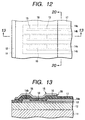
- the major part of its substrate unit is shown in Fig. 12, which is a plan view.
- Figs. 13 and 20 show the 13-13 and 20-20 sections, respectively, of the plan view shown in Fig. 12; where, a substrate 11 as the recording device substrate H1100 supports the electrothermal transducer 18, which is formed by the heat generating resist layer 13 placed between a pair of the electrode wiring circuits 14a and 14b.
- the step 15 is formed by a pair of the electrode wiring circuits 14a and 14b to stand on the heat generating resist layer 13. They are protected by the first protective layer 17 and second protective layer 16.
- the ink is supplied to the ink chamber 20 via the ink supply port 21 (corresponding to the ink supply port H1201), opened in the substrate 11, and then supplied from the ink chamber 20 to the discharge port 19.
- the substrate 11 is normally produced by the following procedures: the heat generating resist layer 13 and a pair of the electrode wiring circuits 14a and 14b are normally patterned on an Si wafer by photolithography; the ink chamber 20 and the discharge port 19 are made of a photosensitive resin; the ink supply port 21 is formed by anisotropic etching or the like; and the Si wafer is cut off.
- the electrical wiring substrate H1300 responsible for transmitting/receiving the electrical signal to drive the electrothermal transducer 18, is connected to the substrate 11 by a mounting technique.
- the electrical wiring substrate H1300 supports driving devices, e.g., power transistor for electrically switching the electrothermal transducer 18 on or off, and CMOS logic circuit for controlling the power transistor, formed by the semiconductor techniques to be connected to the electrothermal transducer 18 via a pair of the electrode wiring circuits 14a and 14b.
- driving devices e.g., power transistor for electrically switching the electrothermal transducer 18 on or off
- CMOS logic circuit for controlling the power transistor, formed by the semiconductor techniques to be connected to the electrothermal transducer 18 via a pair of the electrode wiring circuits 14a and 14b.
- the discharge ports 19 were formed in two rows running in parallel to each other sandwiching the ink supply port 21, each port in one row being off the corresponding one in the other row by half a pitch, and the ink chambers 20 were arranged at intervals of 600 dpi for the corresponding discharge ports 19.
- Each of the ink chambers 20 was provided with the electrothermal transducer 18, to discharge the ink droplets from the discharge port 19 at 4 picoliter.
- the substrate 11 was made of an Si wafer, which was thermally oxidized to form the oxide layer 12 as a several ⁇ m thick SiO 2 film. It was then coated with the heat generating resist layer 13 (around 500 ⁇ thick) by sputtering.
- the heat generating resist layer 13 was made of TaN, which may be replaced by, e.g., HfB 2 or TaSiN.
- the Al layer for a pair of the electrode wiring circuits 14a and 14b was formed to a thickness of around 2100 ⁇ with a tolerance of ⁇ 300 ⁇ , and patterned on the wiring region using a mask.
- the electrode wiring circuits 14a and 14b were made of Al, which may be replaced by an alloy, e.g., Al-Si, Al-Cu or Al-si-Cu.
- the heat generating resist layer 13 and a pair of the electrode wiring circuits 14a and 14b were simultaneously treated by dry etching, and the electrothermal transducer 18 is patterned using a mask. Then, the Al layer in the electrothermal transducer 18 area was removed by wet etching.
- Thickness of the Al layer for a pair of the electrode wiring circuits 14a and 14b was decreased to around 2100 ⁇ . Decreasing the thickness increases wiring resistance, which increases power consumption and temperature of the substrate 11. Therefore, the conventional device has a thicker circuit.
- the minimum allowable thickness of the electrode wiring circuits 14a and 14b is largely determined by current density, which represents how much current flows for how long in the unit cross sectional area, which is determined by its width and thickness. It is generally well known that resistance of the material that constitutes the electrode wiring circuit 14a and 14b by electromigration increases as current density and conducting period increase.
- the electrode wiring circuits 14a and 14b over the substrate 11 are exposed to 3 ⁇ 10 8 to 1 ⁇ 10 9 conducting cycles, each lasting a very short time of 1 ⁇ min, at a repeated driving frequency of 30 kHz or so.
- Example 1 The substrate 11 of Example 1 was analyzed for electromigration at its electrode wiring circuits 14a and 14b. No change in resistance of these circuits was observed for 3 ⁇ 10 9 pulses under the conditions of current density of 1.5 ⁇ 10 7 A/cm, conducting pulse width of 1.3 ⁇ s and substrate temperature of constant 60°C.
- the electrode wiring circuits 14a and 14b were coated with the first protective layer 17 of SiN, formed by CVD to a thickness of 3000 ⁇ with a tolerance of ⁇ 400 ⁇ .
- SiN may be replaced by silicon oxide.
- the second protective layer 16 of Ta was formed by sputtering to a thickness of 2300 ⁇ with a tolerance of ⁇ 280 ⁇ .
- Ta may be replaced by TaN or TaSiN.
- the patterning was again effected, and unnecessary portion of the second protective layer 16 of Ta was removed by dry etching. Dry etching time was set for overetching, to prevent the second protective layer 16 from remaining in the cavity 22 between the heat generating resist layers 13 (and electrode wiring circuits 14a and 14b which were placed on the resist layers alternately) arranged in parallel to the direction of the electrothermal transducer 18 row.
- the residual area When the second protective layer 16 remains, and when there is a pinhole in the first protective layer 17 below the area where the second protective layer 16 remains (hereinafter referred to as the residual area), the wiring electrode and residual area are electrically connected to each other, to possibly oxidize the residual area. The necessary portion of the second protective layer 16 can be oxidized, when the current reaches there.
- the layer 16 may not provide protection against cavitation.
- the dry etching is effected preferably to an overetching extent of at least 100 ⁇ . This overetching will make the first protective layer 17 thinner in the area where the second protective layer 16 is removed than in the area where Ta that constitutes the second protective layer 16 remains. The difference is preferably 200 ⁇ or less, in order to securely protect the electrode wiring.
- This relaxes inflow of the etchant gas into the above portion of the first protective layer 17, even when it is cracked, preventing damages of the heat generating resist layer 13 and electrode wiring circuits 14a and 14b placed on the resist layer 13.
- the portion around the step 23 is etched faster than the others, because of its rougher film texture, to possibly cause damages of the electrode wiring circuits 14a and 14b.
- Fig. 14 shows the substrate surface conditions wet-etched to remove the unnecessary portion of the second protective layer 16
- Fig. 15 shows the XV-XV section of the structure shown in Fig. 14, where the members shown in these figures are marked with the same numbers, when they are functionally corresponding to each other. It is found, when wet etching is used to remove the unnecessary portion of the second protective layer 16, that the etchant penetrates into the first protective layer 17 around the step 23 through the cracks, to etch the electrode wiring circuits 14a and 14b, producing the defect 24.
- the overetching by dry etching can taper the portion of the first protective layer covered by the second protective layer and portion of the first protective layer not covered by the second protective layer in the vicinity of the boundary between them.
- the tapered shape will be described more concretely in Example 2.
- the recording head H1001 was produced by incorporating the above substrate unit, and exposed to cycles of ink injection to test its durability. Disconnection of the wiring for the heat generating resist layer 13 or other troubles were not observed for 1 ⁇ 10 9 cycles, as compared with 3 ⁇ 10 8 cycles or more set as the target.
- the first protective layer 17 was approximately 1.14 times thicker than the layer of the electrode wiring circuit 14a or 14b.
- Fig. 21 is a plan view showing the major portion of the liquid discharging head prepared in Example 2
- Fig. 22 is an 22-22 sectional view of the head shown in Fig. 21, where the devices marked with 25 and 26 are the member for forming the discharge port, and adhesive layer to improve adhesion between the substrate and member for forming the discharge port, respectively.
- the assembly of the substrate and member for forming the discharge port corresponds to the recording device substrate H1100.
- the other structural features and effects are similar to those associated with the recording head H1001 of Example 1.
- the liquid discharging head shown in Figs. 21 and 22 was fabricated by assembling the adhesive layer 26 and member for forming the discharge port 25 with the substrate unit 27 for the liquid discharging head, similar to that described in Example 1.
- the substrate unit 27 for the liquid discharging head similar to that described in Example 1, was coated with polyether amide resin to a thickness of 2.0 ⁇ m as the adhesive layer 26 by the following procedure.
- the polyether amide resin (Hitachi Chemical Co., Ltd., HIMAL1200) was spread over the substrate unit 27 by a spinner, and baked at 100°C for 30 min and 250°C for 1 hour.
- the resin layer was then patterned using a positive resist (Tokyo Ohka Kogyo Co., Ltd., OFPR800), and further patterned by an O 2 plasma asher with the OFPR patterns serving as the mask.
- the OFPR patterns as the mask were removed, to form the adhesive layer 26, shown in Figs. 21 and 22.
- the substrate unit was coated with a positive resist (Tokyo Ohka Kogyo Co., Ltd., ODUR), a dissolvable photosensitive material, and patterned to have 12 ⁇ m thick ink passage patterns (not shown).
- a positive resist Tokyo Ohka Kogyo Co., Ltd., ODUR
- a dissolvable photosensitive material a dissolvable photosensitive material
- a coating resin layer as the member 25 for forming the discharge port was formed on the substrate unit 27, and the discharge port 19 was formed by patterning.
- the coating resin layer is preferably photosensitive, because it helps form the discharge port 19 easily and precisely by photolithography.
- an epoxy resin hardened by cationic polymerization was used for its adhesion to the substrate unit 27 and resistance to ink.
- the SiN film on the ink discharge port 21 and ink passage patterns of ODUR were removed by chemical dry etching (CDE) for the former and immersion in a dissolving solution for the latter, and the epoxy resin for the member 25 for forming the discharge port was heated and completely hardened at 180°C for 1 hour, to prepare the liquid discharging head.
- CDE chemical dry etching
- the member 25 for forming the discharge port was joined with portion of the second protective layer 16 and portion of the first protective layer 17 not covered by the second protective layer 16, as shown in Figs. 21 and 22, via the adhesive layer 26.
- the substrate unit 27, coated with the first protective layer 17 and second protective layer 16, is adhered faster to the member 25 for forming the discharge port via the adhesion layer 26.
- the increased adhesion realized in this example prevents exfoliation of the member 25 for forming the discharge port, thereby improving reliability of the liquid discharging head, as discussed below.
- the side wall 28 is formed, in addition to the second protective layer 16, by the first protective layer 17 in the vicinity of the boundary between the portion of the first protective layer 17 covered by the second protective layer 16 and that of the first protective layer 17 not covered by the second protective layer 16.
- adhesion between the first protective layer 17 and adhesive layer 26 on the substrate unit 27 for the liquid discharging head is improved in the vicinity of the second protective layer 16, efficiently preventing exfoliation of the member 25 for forming the discharge port.
- the side wall 28 can be tapered, when it is formed by dry etching for overetching.
- Fig. 13, used for describing Example 1 shows the first protective layer 17 and second protective layer 16 tapered at almost the same angle.
- Fig. 22 shows another embodiment in the first protective layer 17 is tapered more moderately than the second protective layer 16.
- the tapered shape may have a radius.
- the first protective layer 17 and second protective layer 16 should be tapered at a sharper angle, in order to improve the adhesion.
- Examples 1 and 2 describe the side shooter type recording head H1001, in which the discharge port 19 and electrothermal transducer 18 face each other.
- the present invention is also applicable to an edge shooter type ink jet head, in which the discharge port is opened in the direction almost perpendicular to the electrothermal transducer surface.
- Fig. 16 is an oblique view showing appearances of this embodiment of the present invention for liquid discharging head, where the members shown are marked with the same numbers, when they are functionally corresponding to those shown in other figures.
- the substrate 11 supports the grooved member 25 joined therewith, and between them there are discharge ports 19 arranged at given intervals, common ink chamber 27 from which the ink is supplied to each discharge port 19 via the ink passage 26, and ink supply ports 28 through which the ink is supplied to the ink chamber 27.
- the electrothermal transducer 18 gives thermal energy to the ink flowing in the ink passage 26 for film boiling, to discharge droplets of the ink from each discharge port 19.
- the other members have the same functions as those marked with the same numbers in the other figures.
- the electrothermal transducer 18 formed on the substrate 11 in this example is structurally the same as those for the other examples.
- the substrate unit for liquid discharging head is for a head which gives thermal energy to the liquid for film boiling, to discharge droplets of the liquid from its discharge port.
- the substrate unit includes an electrothermal transducer provided on the substrate surface to generate thermal energy, a pair of electrode wiring circuits provided on the substrate surface and connected to the transducer, first protective layer formed over the substantially entire surface of the substrate to cover a pair of the electrode wiring circuits and transducer, and second protective layer formed over the first protective layer to cover the transducer and the area where the transducer is connected to the wiring circuit, in which a pair of the electrode wiring circuits are 1800 to 2400 ⁇ thick, and the portion of the first protective layer covered by the second protective layer is 2600 to 3400 ⁇ thick and thicker than the portion of the first protective layer not covered by the second protective layer.
Abstract
Description
Claims (25)
- A substrate unit for liquid discharging head which gives thermal energy to a liquid for film boiling, to discharge droplets of the liquid from its discharge port, comprising:an electrothermal transducer provided on the substrate surface to generate thermal energy;a pair of electrode wiring circuits provided on the substrate surface and connected to said electrothermal transducer;a first protective layer formed over the essentially entire surface of the substrate to cover a pair of said electrode wiring circuits and transducer; anda second protective layer formed over the first protective layer to cover said transducer and the area in which said transducer is connected to said wiring circuit,
wherein:a pair of said electrode wiring circuits are 1800 to 2400Å thick; andthe portion of said first protective layer covered by said second protective layer is 2600 to 3400Å thick and thicker than the portion of said first protective layer not covered by the second protective layer. - The substrate unit for liquid discharging head according to claim 1, wherein a pair of said electrode wiring circuits are preferably 2000 to 2200Å thick.
- The substrate unit for liquid discharging head according to claim 1, wherein difference in thickness between the portion of said first protective layer covered by said second protective layer and that of said first protective layer not covered by said second protective layer is 200Å or less.
- The substrate unit for liquid discharging head according to claim 1, wherein difference in thickness between the portion of said first protective layer covered by said second protective layer and that of said first protective layer not covered by said second protective layer is 100Å or more.
- The substrate unit for liquid discharging head according to claim 1, wherein said first protective layer is at least 1.08 times thicker than a pair of said electrode wiring circuits.
- A method for producing a substrate unit for liquid discharging head which gives thermal energy to a liquid for film boiling, to discharge droplets of the liquid from its discharge port, comprising:a step of forming an electrothermal transducer on the substrate surface to generate thermal energy;a step of forming a pair of electrode wiring circuits on the substrate surface in such a way to connect them to said electrothermal transducer;a step of forming a 2600 to 3400Å thick, first protective layer over the essentially entire surface of the substrate to cover a pair of said electrode wiring circuits and said electrothermal transducer; anda step of forming, by dry etching, a second protective layer over said first protective layer to cover said electrothermal transducer and the area in which said electrothermal transducer is connected to said wiring circuit, in such a way to keep the portion of said first protective layer not covered by said second protective layer thinner than the one covered by said second protective layer,
wherein the thickness of a pair of said electrode wiring circuits is kept at 1800 to 2400Å. - The method for producing a substrate unit for liquid discharging head according to claim 6, wherein said second protective layer is formed by dry etching to keep thickness of portion of said first protective layer not covered by said second protective layer at 200Å or less.
- The method for producing a substrate unit for liquid discharging head according to claim 6, wherein said second protective layer is formed by dry etching to keep thickness of portion of said first protective layer not covered by said second protective layer at 100Å or more.
- A liquid discharging head, comprising:discharge ports from which the liquid is discharged;an electrothermal transducer on the substrate surface to generate thermal energy for causing film boiling of the liquid;a pair of electrode wiring circuits provided on the substrate surface and electrically connected to said electrothermal transducer;a first protective layer formed over the essentially entire surface of the substrate to cover a pair of said electrode wiring circuits and electrothermal transducer; anda second protective layer formed over said first protective layer to cover said electrothermal transducer and the area in which said electrothermal transducer is connected to said wiring circuit,
wherein:a pair of said electrode wiring circuits are 1800 to 2400Å thick; andthe portion of said first protective layer covered by said second protective layer is 2600 to 3400Å thick and thicker than the portion of said first protective layer not covered by said second protective layer. - The liquid discharging head according to claim 9, wherein said discharge ports are formed at intervals of 600 dpi in at least two rows running in parallel to each other, each of said discharge ports in one row being off the corresponding one in the other row by half a pitch.
- The liquid discharging head according to claim 9, wherein said liquid is an ink and/or a treatment solution for adjusting printability of the ink on a printing medium.
- The liquid discharging head according to claim 9, wherein said liquid is discharged by driving pulses given to said electrothermal transducer from said discharge port at 5 picoliter or less.
- The liquid discharging head according to claim 9, wherein said head has an additional member for forming said discharge port, which is joined with portion of said second protective layer and portion of said first protective layer not covered by said second protective layer via an adhesive layer.
- The liquid discharging head according to claim 13, wherein said first and second protective layers are tapered in the vicinity of the boundary between the portion of said first protective layer covered by said second protective layer and the one not covered by said second protective layer.
- The liquid discharging head according to claim 14, wherein said first protective layer is tapered at a sharper angle than said second protective layer.
- The liquid discharging head according to claim 13, wherein said adhesive layer is of polyether amide resin.
- The liquid discharging head according to claim 13, wherein said member for forming the discharge port is of epoxy resin hardened by cationic polymerization.
- The liquid discharging head according to claim 13, wherein said discharge port is installed at the side facing said electrothermal transducer.
- A cartridge, comprising a liquid discharging head and liquid tank storing the liquid to be supplied to said liquid discharging head, in which said liquid discharging head comprises,a discharge port from which the liquid is discharged,an electrothermal transducer on the substrate surface to generate thermal energy for causing film boiling of said liquid,a pair of electrode wiring circuits provided on the substrate surface and connected to said electrothermal transducer,a first protective layer formed over the essentially entire surface of the substrate to cover a pair of said electrode wiring circuits and electrothermal transducer, anda second protective layer formed over said first protective layer to cover said electrothermal transducer and the area in which said electrothermal transducer is connected to said wiring circuit,
wherein:a pair of said electrode wiring circuits is 1800 to 2400Å thick; andthe portion of said first protective layer covered by said second protective layer is 2600 to 3400Å thick and thicker than the portion of said first protective layer not covered by said second protective layer. - The cartridge according to claim 19, wherein said liquid tank is releasably attached to said liquid discharging head.
- The cartridge according to claim 19, wherein said liquid discharging head has an additional member for forming the discharge port, which is joined with portion of said first protective layer not covered by said second protective layer and portion of said second protective layer via an adhesive layer.
- An image forming apparatus, provided with a section of attaching a liquid discharging head comprising:discharge ports from which the liquid is discharged;an electrothermal transducer on the substrate surface to generate thermal energy for causing film boiling of the liquid;a pair of electrode wiring circuits provided on the substrate surface and connected to said electrothermal transducer;a first protective layer formed over the essentially entire surface of the substrate to cover a pair of said electrode wiring circuits and electrothermal transducer; anda second protective layer formed over said first protective layer to cover said electrothermal transducer and the area in which said electrothermal transducer is connected to said wiring circuit,
wherein:a pair of said electrode wiring circuits is 1800 to 2400Å thick; andthe portion of said first protective layer covered by said second protective layer is 2600 to 3400Å thick and thicker than the portion of said first protective layer not covered by said second protective layer. - The image forming apparatus according to claim 22, wherein said section of attaching the liquid discharging head has a carriage which can be scanned in the direction intersecting the direction of travel of the printing medium onto which the liquid is discharged from the liquid discharging head.
- The image forming apparatus according to claim 23, wherein said liquid discharging head is releasably attached to said carriage by attaching/detaching means.
- The image forming apparatus according to claim 22, wherein said liquid discharging head has an additional member for forming the discharge port, which is joined with portion of said second protective layer and portion of said first protective layer not covered by said second protective layer via an adhesive layer.
Applications Claiming Priority (4)
| Application Number | Priority Date | Filing Date | Title |
|---|---|---|---|
| JP23629199 | 1999-08-24 | ||
| JP23629199 | 1999-08-24 | ||
| JP2000250081A JP3647365B2 (en) | 1999-08-24 | 2000-08-21 | Substrate unit for liquid discharge head, method for manufacturing the same, liquid discharge head, cartridge, and image forming apparatus |
| JP2000250081 | 2000-08-21 |
Publications (3)
| Publication Number | Publication Date |
|---|---|
| EP1078758A2 true EP1078758A2 (en) | 2001-02-28 |
| EP1078758A3 EP1078758A3 (en) | 2001-10-31 |
| EP1078758B1 EP1078758B1 (en) | 2005-11-30 |
Family
ID=26532596
Family Applications (1)
| Application Number | Title | Priority Date | Filing Date |
|---|---|---|---|
| EP00118081A Expired - Lifetime EP1078758B1 (en) | 1999-08-24 | 2000-08-23 | Substrate unit for liquid discharging head, method for producting the same, liquid discharging head, cartridge, and image forming apparatus |
Country Status (4)
| Country | Link |
|---|---|
| US (1) | US6467884B1 (en) |
| EP (1) | EP1078758B1 (en) |
| JP (1) | JP3647365B2 (en) |
| DE (1) | DE60024371T2 (en) |
Cited By (7)
| Publication number | Priority date | Publication date | Assignee | Title |
|---|---|---|---|---|
| WO2002083424A1 (en) | 2001-04-13 | 2002-10-24 | Sony Corporation | Liquid injection head, liquid injection device, and method of manufacturing liquid injection head |
| EP1270228A1 (en) * | 2001-06-28 | 2003-01-02 | Hewlett-Packard Company | Fluid ejection device and method of manufacturing |
| WO2004060681A1 (en) * | 2002-12-27 | 2004-07-22 | Canon Kabushiki Kaisha | Substrate for ink jet head, ink jet head utilizing the same and producing method therefor |
| EP2070703A1 (en) * | 2007-12-12 | 2009-06-17 | Samsung Electronics Co., Ltd. | Inkjet Printhead and Method of Manufacturing the Same |
| US7753495B2 (en) | 2002-12-27 | 2010-07-13 | Canon Kabushiki Kaisha | Ink jet recording head, manufacturing method therefor, and substrate for ink jet recording head manufacture |
| US8877290B2 (en) * | 2012-10-02 | 2014-11-04 | Canon Kabushiki Kaisha | Method for producing liquid-ejection head |
| CN111148578A (en) * | 2017-08-31 | 2020-05-12 | 佳能株式会社 | Apparatus and method for producing liquid containing ultrafine bubbles |
Families Citing this family (14)
| Publication number | Priority date | Publication date | Assignee | Title |
|---|---|---|---|---|
| JP3937804B2 (en) | 2001-10-30 | 2007-06-27 | キヤノン株式会社 | Method for manufacturing structure having through hole |
| JP3734246B2 (en) | 2001-10-30 | 2006-01-11 | キヤノン株式会社 | Liquid discharge head and structure manufacturing method, liquid discharge head, and liquid discharge apparatus |
| US6955417B2 (en) * | 2002-03-28 | 2005-10-18 | Fuji Photo Film Co., Ltd. | Inkjet recording head and inkjet printer |
| CN100581824C (en) | 2003-02-13 | 2010-01-20 | 佳能株式会社 | Ink jet recording head substrate manufacturing method |
| JP2005067164A (en) * | 2003-08-28 | 2005-03-17 | Sony Corp | Liquid ejection head, liquid ejector, and process for manufacturing liquid ejection head |
| US7022203B2 (en) * | 2003-11-07 | 2006-04-04 | Henkel Consumer Adhesives, Inc. | Electric laminator |
| JP4522086B2 (en) * | 2003-12-15 | 2010-08-11 | キヤノン株式会社 | Beam, beam manufacturing method, ink jet recording head including beam, and ink jet recording head manufacturing method |
| JP4537246B2 (en) * | 2004-05-06 | 2010-09-01 | キヤノン株式会社 | Method for manufacturing substrate for ink jet recording head and method for manufacturing recording head using the substrate manufactured by the method |
| US7195343B2 (en) * | 2004-08-27 | 2007-03-27 | Lexmark International, Inc. | Low ejection energy micro-fluid ejection heads |
| JP4605760B2 (en) * | 2004-11-08 | 2011-01-05 | キヤノン株式会社 | Method for manufacturing heating resistor film and method for manufacturing substrate for recording head |
| JP2006130868A (en) * | 2004-11-09 | 2006-05-25 | Canon Inc | Inkjet recording head and its manufacturing method |
| JP4641440B2 (en) * | 2005-03-23 | 2011-03-02 | キヤノン株式会社 | Ink jet recording head and method of manufacturing the ink jet recording head |
| JP4656641B2 (en) * | 2005-06-02 | 2011-03-23 | キヤノン株式会社 | Recording head and recording apparatus |
| JP4730537B2 (en) * | 2005-12-28 | 2011-07-20 | セイコーエプソン株式会社 | Method for manufacturing liquid jet head |
Family Cites Families (11)
| Publication number | Priority date | Publication date | Assignee | Title |
|---|---|---|---|---|
| GB1556079A (en) | 1976-01-13 | 1979-11-21 | Boeing Co | Tandem wing airplane |
| US4165058A (en) | 1976-01-13 | 1979-08-21 | The Boeing Company | Tandem wing airplane |
| JPS5459936A (en) | 1977-10-03 | 1979-05-15 | Canon Inc | Recording method and device therefor |
| JPH064323B2 (en) | 1984-05-08 | 1994-01-19 | キヤノン株式会社 | Liquid jet recording head |
| JPS6245283A (en) | 1985-08-23 | 1987-02-27 | Sony Corp | Correction circuit for horizontal deflection distortion |
| JPS6245286A (en) | 1985-08-23 | 1987-02-27 | Hitachi Ltd | Image pickup tube device and its driving method |
| JPS6245237A (en) | 1985-08-23 | 1987-02-27 | Nec Home Electronics Ltd | Spread spectrum power line transmission system |
| JP3179834B2 (en) | 1991-07-19 | 2001-06-25 | 株式会社リコー | Liquid flight recorder |
| US5485158A (en) | 1994-07-21 | 1996-01-16 | The United States Of America As Represented By The Secretary Of The Air Force | Linear near field test facility and process |
| US5710070A (en) | 1996-11-08 | 1998-01-20 | Chartered Semiconductor Manufacturing Pte Ltd. | Application of titanium nitride and tungsten nitride thin film resistor for thermal ink jet technology |
| JP4146933B2 (en) | 1998-06-03 | 2008-09-10 | キヤノン株式会社 | Ink jet head and method of manufacturing ink jet head |
-
2000
- 2000-08-21 JP JP2000250081A patent/JP3647365B2/en not_active Expired - Fee Related
- 2000-08-23 US US09/643,931 patent/US6467884B1/en not_active Expired - Lifetime
- 2000-08-23 EP EP00118081A patent/EP1078758B1/en not_active Expired - Lifetime
- 2000-08-23 DE DE60024371T patent/DE60024371T2/en not_active Expired - Lifetime
Non-Patent Citations (1)
| Title |
|---|
| None |
Cited By (13)
| Publication number | Priority date | Publication date | Assignee | Title |
|---|---|---|---|---|
| CN1319742C (en) * | 2001-04-13 | 2007-06-06 | 索尼公司 | Liquid injection head, liquid injection device, and method of manufacturing liquid injection head |
| EP1378362A1 (en) * | 2001-04-13 | 2004-01-07 | Sony Corporation | Liquid injection head, liquid injection device, and method of manufacturing liquid injection head |
| WO2002083424A1 (en) | 2001-04-13 | 2002-10-24 | Sony Corporation | Liquid injection head, liquid injection device, and method of manufacturing liquid injection head |
| EP1378362A4 (en) * | 2001-04-13 | 2005-12-14 | Sony Corp | Liquid injection head, liquid injection device, and method of manufacturing liquid injection head |
| US7182440B2 (en) | 2001-04-13 | 2007-02-27 | Sony Corporation | Liquid jet apparatus |
| EP1270228A1 (en) * | 2001-06-28 | 2003-01-02 | Hewlett-Packard Company | Fluid ejection device and method of manufacturing |
| WO2004060681A1 (en) * | 2002-12-27 | 2004-07-22 | Canon Kabushiki Kaisha | Substrate for ink jet head, ink jet head utilizing the same and producing method therefor |
| US7393084B2 (en) | 2002-12-27 | 2008-07-01 | Canon Kabushiki Kaisha | Substrate for ink jet head with TaCr alloy protective layer, ink jet head utilizing the same and producing method therefor |
| US7753495B2 (en) | 2002-12-27 | 2010-07-13 | Canon Kabushiki Kaisha | Ink jet recording head, manufacturing method therefor, and substrate for ink jet recording head manufacture |
| EP2070703A1 (en) * | 2007-12-12 | 2009-06-17 | Samsung Electronics Co., Ltd. | Inkjet Printhead and Method of Manufacturing the Same |
| US8877290B2 (en) * | 2012-10-02 | 2014-11-04 | Canon Kabushiki Kaisha | Method for producing liquid-ejection head |
| CN111148578A (en) * | 2017-08-31 | 2020-05-12 | 佳能株式会社 | Apparatus and method for producing liquid containing ultrafine bubbles |
| US11938503B2 (en) | 2017-08-31 | 2024-03-26 | Canon Kabushiki Kaisha | Ultrafine bubble-containing liquid manufacturing apparatus and manufacturing method |
Also Published As
| Publication number | Publication date |
|---|---|
| JP3647365B2 (en) | 2005-05-11 |
| JP2001130003A (en) | 2001-05-15 |
| EP1078758A3 (en) | 2001-10-31 |
| US6467884B1 (en) | 2002-10-22 |
| DE60024371D1 (en) | 2006-01-05 |
| DE60024371T2 (en) | 2006-07-06 |
| EP1078758B1 (en) | 2005-11-30 |
Similar Documents
| Publication | Publication Date | Title |
|---|---|---|
| EP1078758B1 (en) | Substrate unit for liquid discharging head, method for producting the same, liquid discharging head, cartridge, and image forming apparatus | |
| US7950769B2 (en) | Circuit board for ink jet head, ink jet head having the same, method for cleaning the head and ink jet printing apparatus using the head | |
| EP1078760A2 (en) | Print head and ink jet printing apparatus | |
| EP0819533A2 (en) | A method for standardizing an ink jet jet recording head and an ink jet recording head for attaining such standardization, ink jet recording method, and information processing apparatus, and host apparatus | |
| US6074041A (en) | Ink jet recording head having an electric discharge path for releasing static electricity and recording apparatus using same | |
| US6186616B1 (en) | Ink jet head having an improved orifice plate, a method for manufacturing such ink jet heads, and an ink jet apparatus provided with such ink jet head | |
| US6443561B1 (en) | Liquid discharge head, driving method therefor, and cartridge, and image forming apparatus | |
| EP0613781B1 (en) | Ink jet printing head, ink jet head cartridge and printing apparatus | |
| EP1078767B1 (en) | Covering rubber member, print head, storage box, and ink jet printing apparatus | |
| EP0627313B1 (en) | Ink jet recording head and ink jet recording apparatus using same | |
| JP3667117B2 (en) | Ink jet recording apparatus and ejection recovery method in the apparatus | |
| US6039438A (en) | Limiting propagation of thin film failures in an inkjet printhead | |
| EP0659563B1 (en) | Ink jet recording head and ink jet recording apparatus | |
| JP2001191559A (en) | Continuous color ink-jet printing head apparatus and method | |
| JP2002019122A (en) | Substrate for ink jet recording head, ink jet recording head and method of manufacturing the head | |
| US6328422B1 (en) | Ink jet head cartridge having a folded wiring member | |
| US6799833B2 (en) | Ink jet recording head and ink jet recording apparatus | |
| EP0585890B1 (en) | Ink jet head and ink jet apparatus using same | |
| EP0771272A1 (en) | Monolithic printing heads and manufacturing processes therefor | |
| JP4298350B2 (en) | RECORDING HEAD SUBSTRATE, LIQUID DISCHARGE RECORDING HEAD HAVING THE SAME, RECORDING DEVICE, AND METHOD FOR PRODUCING RECORDING HEAD SUBSTRATE | |
| JPH07290710A (en) | Ink jet head and ink jet device | |
| JPH07314688A (en) | Ink-jet head and ink-jet recording device | |
| JP2002019121A (en) | Ink jet recording head and its manufacturing method | |
| JPH06316078A (en) | Ink jet print head, ink jet head cartridge using print head and printer | |
| JP2004216774A (en) | Inkjet recording head |
Legal Events
| Date | Code | Title | Description |
|---|---|---|---|
| PUAI | Public reference made under article 153(3) epc to a published international application that has entered the european phase |
Free format text: ORIGINAL CODE: 0009012 |
|
| AK | Designated contracting states |
Kind code of ref document: A2 Designated state(s): DE ES FR GB IT NL Kind code of ref document: A2 Designated state(s): AT BE CH CY DE DK ES FI FR GB GR IE IT LI LU MC NL PT SE |
|
| AX | Request for extension of the european patent |
Free format text: AL;LT;LV;MK;RO;SI |
|
| PUAL | Search report despatched |
Free format text: ORIGINAL CODE: 0009013 |
|
| AK | Designated contracting states |
Kind code of ref document: A3 Designated state(s): AT BE CH CY DE DK ES FI FR GB GR IE IT LI LU MC NL PT SE |
|
| AX | Request for extension of the european patent |
Free format text: AL;LT;LV;MK;RO;SI |
|
| RIC1 | Information provided on ipc code assigned before grant |
Free format text: 7B 41J 2/14 A, 7B 41J 2/16 B |
|
| 17P | Request for examination filed |
Effective date: 20020215 |
|
| AKX | Designation fees paid |
Free format text: DE ES FR GB IT NL |
|
| GRAP | Despatch of communication of intention to grant a patent |
Free format text: ORIGINAL CODE: EPIDOSNIGR1 |
|
| GRAS | Grant fee paid |
Free format text: ORIGINAL CODE: EPIDOSNIGR3 |
|
| GRAA | (expected) grant |
Free format text: ORIGINAL CODE: 0009210 |
|
| AK | Designated contracting states |
Kind code of ref document: B1 Designated state(s): DE ES FR GB IT NL |
|
| PG25 | Lapsed in a contracting state [announced via postgrant information from national office to epo] |
Ref country code: IT Free format text: LAPSE BECAUSE OF FAILURE TO SUBMIT A TRANSLATION OF THE DESCRIPTION OR TO PAY THE FEE WITHIN THE PRESCRIBED TIME-LIMIT;WARNING: LAPSES OF ITALIAN PATENTS WITH EFFECTIVE DATE BEFORE 2007 MAY HAVE OCCURRED AT ANY TIME BEFORE 2007. THE CORRECT EFFECTIVE DATE MAY BE DIFFERENT FROM THE ONE RECORDED. Effective date: 20051130 Ref country code: NL Free format text: LAPSE BECAUSE OF FAILURE TO SUBMIT A TRANSLATION OF THE DESCRIPTION OR TO PAY THE FEE WITHIN THE PRESCRIBED TIME-LIMIT Effective date: 20051130 |
|
| REG | Reference to a national code |
Ref country code: GB Ref legal event code: FG4D |
|
| REF | Corresponds to: |
Ref document number: 60024371 Country of ref document: DE Date of ref document: 20060105 Kind code of ref document: P |
|
| PG25 | Lapsed in a contracting state [announced via postgrant information from national office to epo] |
Ref country code: ES Free format text: LAPSE BECAUSE OF FAILURE TO SUBMIT A TRANSLATION OF THE DESCRIPTION OR TO PAY THE FEE WITHIN THE PRESCRIBED TIME-LIMIT Effective date: 20060313 |
|
| NLV1 | Nl: lapsed or annulled due to failure to fulfill the requirements of art. 29p and 29m of the patents act | ||
| ET | Fr: translation filed | ||
| PLBE | No opposition filed within time limit |
Free format text: ORIGINAL CODE: 0009261 |
|
| STAA | Information on the status of an ep patent application or granted ep patent |
Free format text: STATUS: NO OPPOSITION FILED WITHIN TIME LIMIT |
|
| 26N | No opposition filed |
Effective date: 20060831 |
|
| PGFP | Annual fee paid to national office [announced via postgrant information from national office to epo] |
Ref country code: FR Payment date: 20130823 Year of fee payment: 14 |
|
| REG | Reference to a national code |
Ref country code: FR Ref legal event code: ST Effective date: 20150430 |
|
| PG25 | Lapsed in a contracting state [announced via postgrant information from national office to epo] |
Ref country code: FR Free format text: LAPSE BECAUSE OF NON-PAYMENT OF DUE FEES Effective date: 20140901 |
|
| PGFP | Annual fee paid to national office [announced via postgrant information from national office to epo] |
Ref country code: GB Payment date: 20170830 Year of fee payment: 18 |
|
| PGFP | Annual fee paid to national office [announced via postgrant information from national office to epo] |
Ref country code: DE Payment date: 20171030 Year of fee payment: 18 |
|
| REG | Reference to a national code |
Ref country code: DE Ref legal event code: R119 Ref document number: 60024371 Country of ref document: DE |
|
| GBPC | Gb: european patent ceased through non-payment of renewal fee |
Effective date: 20180823 |
|
| PG25 | Lapsed in a contracting state [announced via postgrant information from national office to epo] |
Ref country code: DE Free format text: LAPSE BECAUSE OF NON-PAYMENT OF DUE FEES Effective date: 20190301 |
|
| PG25 | Lapsed in a contracting state [announced via postgrant information from national office to epo] |
Ref country code: GB Free format text: LAPSE BECAUSE OF NON-PAYMENT OF DUE FEES Effective date: 20180823 |