EP1077830B1 - Vehicle seat assembly with thermoformed fibrous suspension panel - Google Patents
Vehicle seat assembly with thermoformed fibrous suspension panel Download PDFInfo
- Publication number
- EP1077830B1 EP1077830B1 EP99916512A EP99916512A EP1077830B1 EP 1077830 B1 EP1077830 B1 EP 1077830B1 EP 99916512 A EP99916512 A EP 99916512A EP 99916512 A EP99916512 A EP 99916512A EP 1077830 B1 EP1077830 B1 EP 1077830B1
- Authority
- EP
- European Patent Office
- Prior art keywords
- seat assembly
- vehicle seat
- fibers
- panel
- suspension panel
- Prior art date
- Legal status (The legal status is an assumption and is not a legal conclusion. Google has not performed a legal analysis and makes no representation as to the accuracy of the status listed.)
- Expired - Lifetime
Links
- 239000000725 suspension Substances 0.000 title claims description 48
- 239000000835 fiber Substances 0.000 claims description 38
- 229920005989 resin Polymers 0.000 claims description 19
- 239000011347 resin Substances 0.000 claims description 19
- -1 polypropylene Polymers 0.000 claims description 15
- 239000004743 Polypropylene Substances 0.000 claims description 12
- 229920001155 polypropylene Polymers 0.000 claims description 12
- 229920001169 thermoplastic Polymers 0.000 claims description 6
- 239000004416 thermosoftening plastic Substances 0.000 claims description 6
- XLYOFNOQVPJJNP-UHFFFAOYSA-N water Substances O XLYOFNOQVPJJNP-UHFFFAOYSA-N 0.000 claims description 5
- PPBRXRYQALVLMV-UHFFFAOYSA-N Styrene Chemical compound C=CC1=CC=CC=C1 PPBRXRYQALVLMV-UHFFFAOYSA-N 0.000 claims description 4
- JOYRKODLDBILNP-UHFFFAOYSA-N Ethyl urethane Chemical compound CCOC(N)=O JOYRKODLDBILNP-UHFFFAOYSA-N 0.000 claims description 3
- 240000000797 Hibiscus cannabinus Species 0.000 claims description 3
- 239000004677 Nylon Substances 0.000 claims description 3
- 229920001778 nylon Polymers 0.000 claims description 3
- 229920000728 polyester Polymers 0.000 claims description 3
- 229920001187 thermosetting polymer Polymers 0.000 claims description 3
- 239000004593 Epoxy Substances 0.000 claims description 2
- 239000004698 Polyethylene Substances 0.000 claims description 2
- NIXOWILDQLNWCW-UHFFFAOYSA-N acrylic acid group Chemical group C(C=C)(=O)O NIXOWILDQLNWCW-UHFFFAOYSA-N 0.000 claims description 2
- 229920006243 acrylic copolymer Polymers 0.000 claims description 2
- 239000005038 ethylene vinyl acetate Substances 0.000 claims description 2
- 210000003127 knee Anatomy 0.000 claims description 2
- 210000004705 lumbosacral region Anatomy 0.000 claims description 2
- 229920001200 poly(ethylene-vinyl acetate) Polymers 0.000 claims description 2
- 229920000573 polyethylene Polymers 0.000 claims description 2
- 229920002689 polyvinyl acetate Polymers 0.000 claims description 2
- 239000011118 polyvinyl acetate Substances 0.000 claims description 2
- 229920003048 styrene butadiene rubber Polymers 0.000 claims description 2
- 229920002554 vinyl polymer Polymers 0.000 claims description 2
- 229920005992 thermoplastic resin Polymers 0.000 claims 1
- 239000000463 material Substances 0.000 description 9
- 239000011230 binding agent Substances 0.000 description 5
- 239000004744 fabric Substances 0.000 description 5
- 238000000034 method Methods 0.000 description 4
- 239000004033 plastic Substances 0.000 description 4
- 229920003023 plastic Polymers 0.000 description 4
- 230000008569 process Effects 0.000 description 4
- 238000004519 manufacturing process Methods 0.000 description 3
- 239000000203 mixture Substances 0.000 description 3
- 238000000465 moulding Methods 0.000 description 3
- 238000003856 thermoforming Methods 0.000 description 3
- 239000004634 thermosetting polymer Substances 0.000 description 3
- 229920000742 Cotton Polymers 0.000 description 2
- 230000008901 benefit Effects 0.000 description 2
- 230000007613 environmental effect Effects 0.000 description 2
- 238000002844 melting Methods 0.000 description 2
- 230000008018 melting Effects 0.000 description 2
- 238000004064 recycling Methods 0.000 description 2
- 241000218033 Hibiscus Species 0.000 description 1
- 229920001131 Pulp (paper) Polymers 0.000 description 1
- 229910000831 Steel Inorganic materials 0.000 description 1
- 238000010521 absorption reaction Methods 0.000 description 1
- 239000000853 adhesive Substances 0.000 description 1
- 230000001070 adhesive effect Effects 0.000 description 1
- 230000004075 alteration Effects 0.000 description 1
- 230000000712 assembly Effects 0.000 description 1
- 238000000429 assembly Methods 0.000 description 1
- 235000013361 beverage Nutrition 0.000 description 1
- 210000001217 buttock Anatomy 0.000 description 1
- 239000007795 chemical reaction product Substances 0.000 description 1
- 238000010276 construction Methods 0.000 description 1
- 230000006866 deterioration Effects 0.000 description 1
- 239000002657 fibrous material Substances 0.000 description 1
- 239000006260 foam Substances 0.000 description 1
- 239000006261 foam material Substances 0.000 description 1
- 238000010169 landfilling Methods 0.000 description 1
- 230000007246 mechanism Effects 0.000 description 1
- 229910052751 metal Inorganic materials 0.000 description 1
- 239000002184 metal Substances 0.000 description 1
- 150000002739 metals Chemical class 0.000 description 1
- 229920000139 polyethylene terephthalate Polymers 0.000 description 1
- 239000005020 polyethylene terephthalate Substances 0.000 description 1
- 239000000047 product Substances 0.000 description 1
- 239000002994 raw material Substances 0.000 description 1
- 239000010959 steel Substances 0.000 description 1
- KKEYFWRCBNTPAC-UHFFFAOYSA-L terephthalate(2-) Chemical compound [O-]C(=O)C1=CC=C(C([O-])=O)C=C1 KKEYFWRCBNTPAC-UHFFFAOYSA-L 0.000 description 1
- 239000012815 thermoplastic material Substances 0.000 description 1
Images
Classifications
-
- B—PERFORMING OPERATIONS; TRANSPORTING
- B60—VEHICLES IN GENERAL
- B60N—SEATS SPECIALLY ADAPTED FOR VEHICLES; VEHICLE PASSENGER ACCOMMODATION NOT OTHERWISE PROVIDED FOR
- B60N2/00—Seats specially adapted for vehicles; Arrangement or mounting of seats in vehicles
- B60N2/70—Upholstery springs ; Upholstery
-
- A—HUMAN NECESSITIES
- A47—FURNITURE; DOMESTIC ARTICLES OR APPLIANCES; COFFEE MILLS; SPICE MILLS; SUCTION CLEANERS IN GENERAL
- A47C—CHAIRS; SOFAS; BEDS
- A47C7/00—Parts, details, or accessories of chairs or stools
- A47C7/02—Seat parts
- A47C7/18—Seat parts having foamed material included in cushioning part
- A47C7/185—Seat parts having foamed material included in cushioning part with a stiff, rigid support
-
- B—PERFORMING OPERATIONS; TRANSPORTING
- B60—VEHICLES IN GENERAL
- B60N—SEATS SPECIALLY ADAPTED FOR VEHICLES; VEHICLE PASSENGER ACCOMMODATION NOT OTHERWISE PROVIDED FOR
- B60N2/00—Seats specially adapted for vehicles; Arrangement or mounting of seats in vehicles
- B60N2/02—Seats specially adapted for vehicles; Arrangement or mounting of seats in vehicles the seat or part thereof being movable, e.g. adjustable
- B60N2/22—Seats specially adapted for vehicles; Arrangement or mounting of seats in vehicles the seat or part thereof being movable, e.g. adjustable the back-rest being adjustable
- B60N2/225—Seats specially adapted for vehicles; Arrangement or mounting of seats in vehicles the seat or part thereof being movable, e.g. adjustable the back-rest being adjustable by cycloidal or planetary mechanisms
- B60N2/2251—Seats specially adapted for vehicles; Arrangement or mounting of seats in vehicles the seat or part thereof being movable, e.g. adjustable the back-rest being adjustable by cycloidal or planetary mechanisms with gears having orbital motion, e.g. sun and planet gears
-
- B—PERFORMING OPERATIONS; TRANSPORTING
- B60—VEHICLES IN GENERAL
- B60N—SEATS SPECIALLY ADAPTED FOR VEHICLES; VEHICLE PASSENGER ACCOMMODATION NOT OTHERWISE PROVIDED FOR
- B60N2/00—Seats specially adapted for vehicles; Arrangement or mounting of seats in vehicles
- B60N2/68—Seat frames
- B60N2/686—Panel like structures
-
- Y—GENERAL TAGGING OF NEW TECHNOLOGICAL DEVELOPMENTS; GENERAL TAGGING OF CROSS-SECTIONAL TECHNOLOGIES SPANNING OVER SEVERAL SECTIONS OF THE IPC; TECHNICAL SUBJECTS COVERED BY FORMER USPC CROSS-REFERENCE ART COLLECTIONS [XRACs] AND DIGESTS
- Y10—TECHNICAL SUBJECTS COVERED BY FORMER USPC
- Y10S—TECHNICAL SUBJECTS COVERED BY FORMER USPC CROSS-REFERENCE ART COLLECTIONS [XRACs] AND DIGESTS
- Y10S297/00—Chairs and seats
- Y10S297/02—Molded
Definitions
- the present invention relates to a vehicle seat assembly corresponding to the preamble of Claims 1 or 2 according to the preamble of Claim 1 or 2.
- EP 02 76 769 A3 discloses a vehicle seat assembly having a seat cushion made of a foam material positioned on a spring support extending between the walls of a seat frame.
- the spring support is a plastic plate secured at the edges between the frame sections.
- EP 03 72 338 A2 discloses a vehicle seat assembly having a frame for a cushion carrier shell.
- the frame is made of two high strength thermoplastic material carrier beams and joined to steel cross members.
- the rear cross member is supported by brackets which are adjustable in guide rails.
- a third way of reducing the negative environmental impact of a vehicle is to reduce the number of individual components in a vehicle by designing components that perform multiple functions instead of just one function. This can reduce the quantity of raw material used in a vehicle as well as reduce the time and energy required to produce the vehicle.
- the most preferred process is to reuse a seat component without any alteration from its original form.
- the next level is to reclaim a component and manufacture it into another useful component. This has been done regularly with most metals in which the reclaimed parts are melted down and remade into a new component.
- the next level is to shred the components, such as the foam pad, into small pieces that can be used in another product such as rebonded carpet padding. This is less desirable in that the carpet padding, after its useful life, is not reused and is land filled.
- Fourth, and least preferred is shredding of the seat components followed by land filling of the shredded materials.
- the seat assembly of the present invention facilitates the recycling of the vehicle seat assembly by providing a suspension panel for supporting the seat pad that can be made of a recycled material and which can be reclaimed and manufactured into a new component after the useful life of the seat assembly.
- a suspension panel for supporting the seat pad that can be made of a recycled material and which can be reclaimed and manufactured into a new component after the useful life of the seat assembly.
- the suspension panel is also used as the rear trim cover of a seat back, multi-tasking is involved, using a single component for both the suspension as well as the rear trim panel. This serves to reduce the number of components in a seat assembly.
- the suspension panel of the present invention is manufactured of a resin or thermoplastic impregnated compressed fibrous bat material.
- Plastic fibers are preferred, such polyethelyne terephthalate (PET) from recycled beverage containers, virgin PET fibers or post industrial polypropylene. Alternatively, offal from various manufacturing processes can be used, such as offal from vehicle head liner manufacturing. Other fibers can be used as well.
- Plastic fibers are preferred over natural fibers such as cotton or wood pulp due to their resistance to absorption of water. However, cotton fibers and other natural fibers can be used in the suspension panel.
- the panels are formed with corrugations and other contours that provide for differing degrees of flexibility in the panel at different locations.
- the suspension panel can be individually designed to provide specific deflection characteristics. The deflection characteristics will be designed in conjunction with the seat pad to provide a desired comfort.
- the suspension panel can be thermoformed and bonded to a covering fabric during the thermoforming process to provide a decorative exterior surface to the suspension panel. This is particularly useful when the panel also serves as a seat shell forming exterior surface of the seat back. A fabric surface matching that of the seat trim cover overlying the seat pad can be bonded directly to the suspension panel.
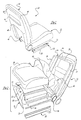
- FIG. 1 A vehicle seat assembly of the present invention having a formed suspension panel is shown in FIG. 1 and designated generally at 10.
- the seat assembly 10 includes a lower generally horizontal seat bottom 12 and a generally upright seat back extending upwardly at the rear end of the seat bottom 12.
- the seat bottom 12 includes a frame 16 (FIG. 2) which is mounted to a slide track 18.
- the slide track 18 includes a fixed rail 20 adapted to be mounted to a motor vehicle body and a slide rail 22 which moves fore and aft upon the fixed rail 20 for adjustment of the fore and aft position of the seat assembly within the motor vehicle.
- the seat back includes a back frame 24 which, as shown in FIG. 2, has upright frame side members 26 on each side of the seat and an upper frame cross member 28 at the upper end of the seat back.
- the seat bottom frame 16 is similarly constructed with frame side members 30 extending along each side of the seat and a front frame cross member 32.
- the seat bottom frame and seat back frame are joined together through a recliner mechanism shown schematically at 34.
- the invention does not require any particular frame structure for the seat bottom and seat back. Those shown are merely exemplary of many possible frame configurations.
- the seat bottom includes formed suspension panel 36 which is attached to the frame 16.
- the suspension panel 36 supports a resilient seat pad 38.
- a trim cover 40 covers the pad 38 and is shown in this embodiment wrapping around the frame 16 and attached to the bottom side of the frame by any one of a variety of known attachments.
- the seat back is similarly constructed with a trim cover 42, a resilient pad (not shown) and a suspension panel 44.
- the suspension panel 44 of the seat back is attached to the back frame 24 and provides support to the resilient pad of the seat back.
- the panel 44 is formed with a forwardly projecting lower portion 46 in the lumbar region of the seat back to provide additional support to the pad in the lumber region of the seat back. As shown in FIG. 1, the forwardly projecting lower end portion 46 of the back panel results in a corresponding recess at the lower end of the back panel when viewed from behind the seat assembly. This provides increased knee room for a person seated behind the seat assembly 10.
- Other raised or forwardly extending portions of the panel can be provided to provide different degrees of support to the pad at various locations within the seat back. For example, the panel can be raised along the side edges of the seat back to increase support in the bolster region of the seat back.
- the panel 44 is attached to the frame with any of a variety of means including the fasteners 48 shown on the back of the seat assembly in FIG. 1.
- the fasteners 48 can be threaded fasteners, snap fasteners, etc.
- the panel 44 can be made with integral projections which insert into apertures in the seat back frame if desired.
- the seat back suspension panel 44 provides suspension and support to the seat pad as well as forming a back trim panel for the seat back. This reduces the number of components in the seat assembly. No longer is a separate spring wire suspension needed in the seat back. Instead, the suspension panel 44 serves both the suspension function as well as the decorative trim for the rear surface of the seat back.
- the panel 36 provides the suspension support to the seat pad 38.
- the panel 36 is formed with different grooves or corrugations 50 to provide different degrees of support and flexibility to the panel 36.
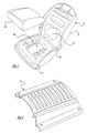
- Alternative embodiments are shown in FIGS. 3 and 4 where the seat bottom suspension panel is shown with the different configurations to provide different degrees of flexibility and suspension support to the seat pad.
- the degree of flexibility in the panel is designed in conjunction with the size, shape, thickness, density etc. of the resilient seat pad to achieve a desired degree of cushioning and comfort for a seat occupant.
- a variety of configurations can be used as illustrated in FIGS. 2, 3 and 4.
- a suspension panel 52 is shown which is a single piece formed panel having a seat bottom portion 54 and seat back portion 56. The two portions are joined together by a living hinge region 58, allowing the bottom and back portions to flex relative to one another as the seat back is reclined to various positions.
- the seat bottom portion is configured with a generally U-shaped recessed portion 60 which corresponds to the buttock region of the seat occupant to provide a greater degree of flexibility in this region of the panel as compared to other regions of the panel for improved comfort.
- the seat back again has a forwardly projecting lower end portion 62 to provide increased lumbar support.
- the suspension panel is made of a fibrous bat impregnated with a binder resin or thermoplastic fibers.
- the fibers are preferably non-woven and are randomly oriented.
- the fibers are needled to cause them to intermesh and then to orient them generally transversely to the planes of the surfaces of the bat.
- the fibers used in the bat are preferably thermoformable. It is desirable that they take a set when placed in a heated mold in the case of the thermoset resin or in a cold mold with thermoplastic so that they hold a three-dimensional configuration.
- Thermoplastic fibers are preferred, though their melting point should be substantially greater than the temperatures to which the end product may be exposed in intended use.
- Non-woven polyester fiber is a particularly preferred material in forming the non-woven fibrous bat because of its excellent elongation and molding characteristics at molding temperatures.
- Other fibers which could be employed include nylon, polypropylene and polyethylene such as polyethylene terephthalate (PET).
- the binder resin that impregnates the bat adheres the fibers to one another.
- the binder resin must be thermoformable to accommodate the molding process. This requires a thermoplastic or equivalent material.
- a binder resin may be selected from the group including: water dispersed urethane, acrylic, ethylene vinyl acetate acrylic, styrene butadiene rubber, polyvinyl acetate, polyvinyl acrylic copolymer, epoxy and water-based styrene.
- the impregnating binder resin of the bat can also be a thermoset resin which provides an advantage that once it is cured, it will have very high resistance to heat distortion or deterioration.
- the thermoset resin is preferably elastomeric in nature so that the suspension panel has elastic characteristics.
- a preferred thermosetting elastomeric resin is elastomeric urethane.
- An alternative material for the suspension panel, other than a resin impregnated fibrous bat, is a blend of organic fibrous materials known as a kenaf, which is the ground up stalk fibers of the hibiscus plant. These fibers are blended with polypropylene in a mixture that can range from about 40% kenaf to 60% polypropylene fibers by weight to a mixture of about 60% kenef and 40% polypropylene fibers.
- the polypropylene is in a fibrous form and the kenef and polypropylene fibers are mixed in a conventional pin cylinder mixer and subsequently oriented and formed into a web using a conventional airlay machine to initially orient the fibers longitudinally and subsequently, by a standard needling machine to entangle the fibers.
- the result is a web of somewhat fluffy mat-material which is then heated to melt the polypropylene fibers.
- the heated mat is placed into a cold tool, compressed and formed into the desired shape.
- other plastic fibers can be used that have a melting point higher than the polypropylene fibers.
- a decorative cover sheet can be applied to the panel prior to the thermoforming of the panel.
- a decorative fabric can be applied to the rear surface of the panel used in the seat back to provide an attractive appearance to the rear of the seat back.
- the fiber of the decorative cover would also be thermoformable so that the cover can be applied to the uncured resin of the bat prior to thermoforming.
- the resin once cured, serves as the adhesive to bond the decorative cover in place on the suspension panel.
- a particular preferred thermoformable polymeric fabric cover sheet comprises a nylon or polyester warp knit cloth material.
Landscapes
- Engineering & Computer Science (AREA)
- Aviation & Aerospace Engineering (AREA)
- Transportation (AREA)
- Mechanical Engineering (AREA)
- Seats For Vehicles (AREA)
Description
Claims (19)
- A vehicle seat assembly (10) comprising:a generally horizontal seat bottom (12);a seat back (14) extending generally upwardly at a rear end of the seat bottom (12); and the seat bottom (12) having a frame (16) with two spaced apart frame side members (30), a suspension panel (52) mounted to the spaced frame side members (30) and spanning across the seat bottom (12) between the frame side members (30), and a seat pad (38) carried by the suspension panel (52) such that the suspension panel (52) transmits seating loads from the seat pad (38) to the frame (16), the suspension panel (52) being formed of a resin impregnated compressed fibrous bat, characterized by the suspension panel is comprising a seat bottom portion (54) configured with a generally U-shaped recessed portion (60), whereby the suspension panel (52) is contoured to provide varying degrees of flexibility at different locations on the panel (52).
- A vehicle seat assembly (10) comprising:a generally horizontal seat bottom (12);a seat back (14) extending generally upwardly at a rear end of the seat bottom (12); and the seat back (14) having a frame (24) with two spaced apart frame side members (26), a suspension panel (44) mounted to the spaced frame side members (26) and spanning across the seat back (14) between the frame side members (26), and a seat pad carried by the suspension panel (44) such that the suspension panel (44) transmits seating loads from the seat pad to the frame (24), characterized by the suspension panel (44) being formed of a resin impregnated compressed fibrous bat and having a forwardly projecting lower end portion (46) to provide increased support to the seat pad in the lumbar region of a seat occupant.
- The vehicle seat assembly of claim 2, wherein the suspension panel (44) forms a rear trim panel on the seat back (14).
- The vehicle seat assembly of claim 3, wherein the suspension panel (44) has a decorative cover layer laminated thereto.
- The vehicle seat assembly of one of claims 2 to 4, wherein the suspension panel (44) in the area of the forwardly projecting lower end portion (46) has a corresponding recess at the lower end when viewed from behind providing increased knee room for an occupant of a seat located behind the seat assembly.
- The vehicle seat assembly of one of claims 1 to 5, wherein the fibers of the bat are thermoformable fibers.
- The vehicle seat assembly of one of claims 1 to 6, wherein the fibers of the bat are thermoplastic fibers.
- The vehicle seat assembly of one of claims 1 to 7, wherein the fibers of the bat are selected from the group of polyester, nylon, polypropylene and polyethylene.
- The vehicle seat assembly of one of claims 1 to 5, wherein a portion of the fibers of the bat are natural fibers.
- The vehicle seat assembly of one of claims 1 to 9, wherein the fibers of the bat are non-woven.
- The vehicle seat assembly of claim 10, wherein the fibers of the bat are needled.
- The vehicle seat assembly of one of claims 1 to 11, wherein the impregnating resin of the bat is a thermosetting resin.
- The vehicle seat assembly of claim 12, wherein the resin is a thermosetting elastomeric resin.
- The vehicle seat assembly of one of claims 1 to 11, wherein the impregnating resin of the bat is a thermoplastic resin.
- The vehicle seat assembly of one of claims 1 to 14, wherein the resin is selected from the group including water dispersed urethane, acrylic, ethylene vinyl acetate acrylic, styrene butadiene rubber, polyvinyl acetate, polyvinyl acrylic copolymer, epoxy and water-based styrene.
- The vehicle seat assembly of one of claims 1 to 15, wherein the suspension panel (52,44) has a decorative skin bonded to one surface thereof.
- The vehicle seat assembly of one of claims 1 to 16, wherein the suspension panel (52,44) is formed with at least one corrugation to alter the flexibility of the panel at the location of the corrugation.
- The vehicle seat assembly of one of claims 1 to 17, wherein the resin impregnated compressed fibrous bat includes fibers imbedded in polypropylene.
- The vehicle seat assembly of claim 18, wherein the fibers imbedded in polypropylene are kenaf fibers.
Applications Claiming Priority (3)
| Application Number | Priority Date | Filing Date | Title |
|---|---|---|---|
| US76544 | 1998-05-12 | ||
| US09/076,544 US6213557B1 (en) | 1998-05-12 | 1998-05-12 | Vehicle seat assembly with thermoformed fibrous suspension panel |
| PCT/US1999/007715 WO1999058363A1 (en) | 1998-05-12 | 1999-04-07 | Vehicle seat assembly with thermoformed fibrous suspension panel |
Publications (2)
| Publication Number | Publication Date |
|---|---|
| EP1077830A1 EP1077830A1 (en) | 2001-02-28 |
| EP1077830B1 true EP1077830B1 (en) | 2003-11-12 |
Family
ID=22132696
Family Applications (1)
| Application Number | Title | Priority Date | Filing Date |
|---|---|---|---|
| EP99916512A Expired - Lifetime EP1077830B1 (en) | 1998-05-12 | 1999-04-07 | Vehicle seat assembly with thermoformed fibrous suspension panel |
Country Status (4)
| Country | Link |
|---|---|
| US (2) | US6213557B1 (en) |
| EP (1) | EP1077830B1 (en) |
| DE (1) | DE69912765T2 (en) |
| WO (1) | WO1999058363A1 (en) |
Cited By (1)
| Publication number | Priority date | Publication date | Assignee | Title |
|---|---|---|---|---|
| WO2024246028A1 (en) * | 2023-06-02 | 2024-12-05 | Brose Fahrzeugteile SE & Co. Kommanditgesellschaft, Coburg | Method for utilising parts of an electrically driven assembly of a motor vehicle, system for evaluating the state of parts of such an assembly, and electrically driven assembly of a motor vehicle |
Families Citing this family (39)
| Publication number | Priority date | Publication date | Assignee | Title |
|---|---|---|---|---|
| US6425637B1 (en) * | 1999-04-19 | 2002-07-30 | Steelcase Development Corporation | Cushion construction for furniture |
| CN1440327A (en) * | 2000-05-04 | 2003-09-03 | 贝尔熔融有限公司 | Method and apparatus for forming article and article formed thereby |
| US20030165690A1 (en) * | 2002-03-04 | 2003-09-04 | Kieltyka Kevin Allen | Color trim panel |
| WO2004039624A1 (en) * | 2002-10-29 | 2004-05-13 | Wilcox Jeffrey S | Seat suspension |
| DE102004018001B4 (en) * | 2004-04-14 | 2007-10-18 | Recaro Gmbh & Co. Kg | Vehicle seat, in particular motor vehicle seat |
| US7067613B2 (en) * | 2004-06-04 | 2006-06-27 | Chemical Products Corporation | Separation of polyolefins from nylons |
| US20060069170A1 (en) * | 2004-09-27 | 2006-03-30 | Chemical Products Corporation | Decomposition of Polyester |
| US20060070188A1 (en) * | 2004-09-27 | 2006-04-06 | Chemical Products Corporation | Colorant Removal from Polymeric Fibers |
| US7540307B1 (en) | 2004-10-06 | 2009-06-02 | Indratech Llc | Machine having variable fiber filling system for forming fiber parts |
| US20060075615A1 (en) * | 2004-10-07 | 2006-04-13 | Indratech Llc | Cushion with aesthetic exterior |
| JP4354421B2 (en) * | 2004-10-12 | 2009-10-28 | トヨタ紡織株式会社 | Manufacturing method of fiber molded body |
| DE102005043552A1 (en) * | 2005-09-12 | 2007-03-15 | GM Global Technology Operations, Inc., Detroit | Motor vehicle with a seat |
| US20080106136A1 (en) * | 2006-04-28 | 2008-05-08 | Heidmann Kurt R | Seat front edge construction |
| US20070273195A1 (en) * | 2006-05-23 | 2007-11-29 | Lear Corporation | Automotive seat cushion pan |
| US20090061198A1 (en) * | 2007-09-04 | 2009-03-05 | Khambete Surendra S | Polyester padding for gymnasium |
| US7677668B2 (en) * | 2008-01-08 | 2010-03-16 | Brunswick Corporation | Vehicle seats having a back support lock assembly |
| EP2154018B1 (en) * | 2008-08-15 | 2013-01-09 | Scherdel Marienberg GmbH | Vehicle seat |
| US7959233B2 (en) * | 2008-12-19 | 2011-06-14 | Toyota Motor Engineering & Manufacturing North America, Inc. | Seat back assembly with integral reinforcement structure |
| US8414053B2 (en) | 2008-12-19 | 2013-04-09 | Toyota Motor Engineering & Manufacturing North America, Inc. | Seat back assembly with integral reinforcement structure |
| US8157322B2 (en) * | 2008-12-22 | 2012-04-17 | Toyota Motor Engineering & Manufacturing North America, Inc. | Seat back assembly with low density frame |
| US7954899B2 (en) * | 2008-12-22 | 2011-06-07 | Toyota Motor Engineering & Manufacturing North America, Inc. | Seat back assembly with an adjustable headrest |
| DE102009017375A1 (en) * | 2009-04-14 | 2010-10-21 | GM Global Technology Operations, Inc., Detroit | Method for producing supporting structure for vehicle seat, involves fastening profile strip at sheet metal part at edge-side such that seat shell is formed, and fastening U-shaped frame to sheet metal part |
| FR2965520A1 (en) * | 2010-10-04 | 2012-04-06 | Peugeot Citroen Automobiles Sa | Seat for motor vehicle, has base with armature that comprises two rigid polymer parts, where one of parts serves as contact interface arranged in contact with vehicle and other part serves as lining interface defining base height in vehicle |
| US8974003B2 (en) * | 2012-03-30 | 2015-03-10 | Toyota Motor Engineering & Manufacturing North America, Inc. | Rear seat cushion sound reduction mat |
| LU92013B1 (en) | 2012-05-30 | 2013-12-02 | Iee Sarl | Vehicle seat suspension mat |
| LU92012B1 (en) * | 2012-05-30 | 2013-12-02 | Iee Sarl | Vehicle seat suspension mat |
| LU92011B1 (en) | 2012-05-30 | 2013-12-02 | Iee Sarl | Vehicle seat suspension mat |
| JP5976508B2 (en) * | 2012-11-19 | 2016-08-23 | トヨタ紡織株式会社 | Vehicle seat |
| JP6148789B2 (en) * | 2013-04-05 | 2017-06-14 | シンガポール・テクノロジーズ・エアロスペース・リミテッドSingapore Technologies Aerospace Ltd | Seat pan for passenger seat and passenger seat |
| US9315131B2 (en) | 2014-01-23 | 2016-04-19 | Ford Global Technologies, Llc | Suspension seat back and cushion system having an inner suspension panel |
| US10214126B2 (en) | 2014-05-27 | 2019-02-26 | Adient Luxembourg Holding S.a.r.l. | Seat back of hybrid construction and a process for forming a seat back of hybrid construction |
| CN109789820A (en) * | 2016-09-27 | 2019-05-21 | 普罗马有限公司 | The seat of vehicle with joint edge |
| JP6475278B2 (en) * | 2017-03-24 | 2019-02-27 | 本田技研工業株式会社 | Vehicle seat |
| US10457175B2 (en) * | 2017-08-15 | 2019-10-29 | GM Global Technology Operations LLC | Cushion with spatially varying lattice structures |
| US10710472B2 (en) * | 2018-01-11 | 2020-07-14 | Ts Tech Co., Ltd. | Vehicle seat |
| EP3748071A1 (en) | 2019-06-04 | 2020-12-09 | Lenzing Aktiengesellschaft | Joint processing of lignocellulose raw material and cellulose-containing lignine-free product |
| CH717706A1 (en) * | 2020-07-31 | 2022-01-31 | Vitra Ag | Support component, armrest with such a support component and chair with such an armrest. |
| US11890998B2 (en) * | 2021-09-30 | 2024-02-06 | Lear Corporation | Seat trim panel |
| USD1105776S1 (en) | 2022-09-22 | 2025-12-16 | Ami Industries, Inc. | Pilot seat |
Citations (1)
| Publication number | Priority date | Publication date | Assignee | Title |
|---|---|---|---|---|
| EP0372338A2 (en) * | 1988-12-09 | 1990-06-13 | Bayer Ag | Seat underpart for vehicle seats |
Family Cites Families (28)
| Publication number | Priority date | Publication date | Assignee | Title |
|---|---|---|---|---|
| US3182377A (en) * | 1963-11-29 | 1965-05-11 | American Seating Co | Theater chair backs and method of cushion assembly |
| US3521929A (en) | 1967-11-09 | 1970-07-28 | Art Metal Knoll Corp | Furniture construction |
| FR2135441A1 (en) * | 1971-05-05 | 1972-12-22 | Peugeot & Renault | Moulded seat upholstery - eg for car seats of polyurethane and plastic sheet |
| US3797887A (en) * | 1971-06-28 | 1974-03-19 | American Seating Co | Seat for urban mass transit vehicles |
| US4077665A (en) * | 1976-04-22 | 1978-03-07 | International Installations | Plastic restaurant booth seat |
| US4073539A (en) | 1976-05-27 | 1978-02-14 | Litton Business Systems, Inc. | Bonded chair construction |
| JPS5588713A (en) | 1978-12-27 | 1980-07-04 | Tachikawa Spring Co | Sheet for car in synthetic resin |
| US4502731A (en) | 1981-06-01 | 1985-03-05 | Snider Robert A | Seat frame |
| DE3524396A1 (en) * | 1985-07-09 | 1987-01-22 | Basf Ag | COMPOSITE MADE OF GLASS MAT REINFORCED POLYPROPYLENE |
| US4776633A (en) | 1986-04-10 | 1988-10-11 | Steelcase Inc. | Integrated chair and control |
| DE3702262A1 (en) | 1987-01-27 | 1988-08-04 | Basf Ag | SEAT FOR MOTOR VEHICLES |
| NL186900C (en) * | 1987-11-27 | 1991-04-02 | Groot Automotives | SANDWICH PANEL AND METHOD FOR MANUFACTURING A SANDWICH PANEL |
| JPH0646364Y2 (en) * | 1989-05-23 | 1994-11-30 | 池田物産株式会社 | Seat back frame |
| IT1232129B (en) * | 1989-07-05 | 1992-01-23 | Fiat Auto Spa | SEAT BACK WITH STRATIFIED STRUCTURE |
| US5369173A (en) * | 1989-06-13 | 1994-11-29 | Sumitomo Chemical Company, Limited | Glass fiber-reinforced resin composition |
| US5101811A (en) * | 1989-09-25 | 1992-04-07 | Sumner Brunswick | Fitted seating apparatus and manufacture |
| CA2004735C (en) | 1989-12-06 | 1996-09-24 | Denis Matte | One-piece shell for a chair |
| US5464273A (en) * | 1991-07-15 | 1995-11-07 | Kotobuki Seating Co. Ltd. | Seat construction |
| DE4128954A1 (en) * | 1991-08-30 | 1993-06-09 | Eca Gmbh & Co. Kg, 5632 Wermelskirchen, De | SEAT PART OF A VEHICLE SEAT |
| ATE143680T1 (en) * | 1992-03-07 | 1996-10-15 | Basf Ag | FLAT COMPOSITE MATERIAL |
| US5413661A (en) * | 1992-05-13 | 1995-05-09 | R+S Stanztechnik Gmbh | Method for producing a laminated structural component with a hard foam reinforcement |
| KR950003362A (en) * | 1993-07-21 | 1995-02-16 | 마에다 가츠노스케 | Fiber Reinforced Thermoplastic Structures, Manufacturing Method and Extruder |
| US5503454A (en) | 1993-10-19 | 1996-04-02 | Tachi-S Co., Ltd. | Arrangement for securing terminal ends of an automotive seat covering member |
| DE4401665C2 (en) | 1994-01-21 | 1997-08-14 | Daimler Benz Ag | Plastic shell for a motor vehicle seat |
| US5522645A (en) | 1994-04-01 | 1996-06-04 | Milsco Manufacturing Company | Seat having retained cushion |
| DE19627546C1 (en) * | 1996-07-09 | 1997-10-23 | Faure Bertrand Sitztech Gmbh | Back rest for road vehicle seat |
| US5775779A (en) * | 1997-03-27 | 1998-07-07 | General Motors Corporation | Polyurethane thermoplastic elastomer membrane for seat suspension |
| DE29718241U1 (en) | 1997-10-15 | 1997-11-27 | Bertrand Faure Sitztechnik GmbH & Co. KG, 31655 Stadthagen | Vehicle seat |
-
1998
- 1998-05-12 US US09/076,544 patent/US6213557B1/en not_active Expired - Fee Related
-
1999
- 1999-04-07 DE DE69912765T patent/DE69912765T2/en not_active Expired - Fee Related
- 1999-04-07 WO PCT/US1999/007715 patent/WO1999058363A1/en not_active Ceased
- 1999-04-07 EP EP99916512A patent/EP1077830B1/en not_active Expired - Lifetime
-
2000
- 2000-11-02 US US09/705,144 patent/US6409269B1/en not_active Expired - Fee Related
Patent Citations (1)
| Publication number | Priority date | Publication date | Assignee | Title |
|---|---|---|---|---|
| EP0372338A2 (en) * | 1988-12-09 | 1990-06-13 | Bayer Ag | Seat underpart for vehicle seats |
Cited By (1)
| Publication number | Priority date | Publication date | Assignee | Title |
|---|---|---|---|---|
| WO2024246028A1 (en) * | 2023-06-02 | 2024-12-05 | Brose Fahrzeugteile SE & Co. Kommanditgesellschaft, Coburg | Method for utilising parts of an electrically driven assembly of a motor vehicle, system for evaluating the state of parts of such an assembly, and electrically driven assembly of a motor vehicle |
Also Published As
| Publication number | Publication date |
|---|---|
| DE69912765T2 (en) | 2004-07-29 |
| DE69912765D1 (en) | 2003-12-18 |
| US6409269B1 (en) | 2002-06-25 |
| US6213557B1 (en) | 2001-04-10 |
| EP1077830A1 (en) | 2001-02-28 |
| WO1999058363A1 (en) | 1999-11-18 |
Similar Documents
| Publication | Publication Date | Title |
|---|---|---|
| US6213557B1 (en) | Vehicle seat assembly with thermoformed fibrous suspension panel | |
| US5551755A (en) | Padded article | |
| US6571411B1 (en) | Seat cushion and method of manufacturing the same | |
| US8662560B2 (en) | Vehicle seating attachment assembly | |
| US5716092A (en) | Visor and method of manufacturing | |
| CN108688576B (en) | Collapsible map bag with thermoformed polyethylene/polypropylene fibers | |
| CZ28994A3 (en) | Process for producing reinforced energy absorbing panel of foamy polyurethane | |
| US5236247A (en) | Insert molded composite plastic seat cushion frame | |
| EP3012155A1 (en) | Main floor part for a small utility vehicle | |
| US12420460B2 (en) | Foam part, in particular for a vehicle seat, method for producing a foam part, and vehicle seat | |
| US5879802A (en) | Vehicle panel material | |
| CN119058504A (en) | Vehicle seat element, in particular motor vehicle seat | |
| JP2021514323A (en) | Automotive floor cover | |
| WO2011106013A1 (en) | Non-woven fiber seating padding | |
| EP1170170A1 (en) | An upholstery item for a motor vehicle | |
| EP4431267A1 (en) | Receptacle assembly for a fastener in filament mesh structure | |
| RU2481780C2 (en) | Laminar article from renewable natural fibers for finishing | |
| KR102142614B1 (en) | Seat back frame with sandwich panel structure and processes for the preparation thereof | |
| JPH11156976A (en) | Skin material for vehicle interior | |
| US20250303941A1 (en) | Seat trim assembly | |
| KR102797054B1 (en) | Vehicle Trunk Luggage Covering Mat And Its Manufacturing Method | |
| JP3258814B2 (en) | Automotive cushion body | |
| EP4458559A1 (en) | Three-dimensional mesh structures and method of assembly | |
| GB2345301A (en) | Vehicle panel material | |
| EP4684961A1 (en) | Sustainable and versatile layer for an automotive part |
Legal Events
| Date | Code | Title | Description |
|---|---|---|---|
| PUAI | Public reference made under article 153(3) epc to a published international application that has entered the european phase |
Free format text: ORIGINAL CODE: 0009012 |
|
| 17P | Request for examination filed |
Effective date: 20001012 |
|
| AK | Designated contracting states |
Kind code of ref document: A1 Designated state(s): DE FR GB IT |
|
| 17Q | First examination report despatched |
Effective date: 20010320 |
|
| GRAG | Despatch of communication of intention to grant |
Free format text: ORIGINAL CODE: EPIDOS AGRA |
|
| GRAG | Despatch of communication of intention to grant |
Free format text: ORIGINAL CODE: EPIDOS AGRA |
|
| GRAH | Despatch of communication of intention to grant a patent |
Free format text: ORIGINAL CODE: EPIDOS IGRA |
|
| GRAH | Despatch of communication of intention to grant a patent |
Free format text: ORIGINAL CODE: EPIDOS IGRA |
|
| GRAA | (expected) grant |
Free format text: ORIGINAL CODE: 0009210 |
|
| AK | Designated contracting states |
Kind code of ref document: B1 Designated state(s): DE FR GB IT |
|
| REG | Reference to a national code |
Ref country code: GB Ref legal event code: FG4D |
|
| REF | Corresponds to: |
Ref document number: 69912765 Country of ref document: DE Date of ref document: 20031218 Kind code of ref document: P |
|
| ET | Fr: translation filed | ||
| PLBE | No opposition filed within time limit |
Free format text: ORIGINAL CODE: 0009261 |
|
| STAA | Information on the status of an ep patent application or granted ep patent |
Free format text: STATUS: NO OPPOSITION FILED WITHIN TIME LIMIT |
|
| 26N | No opposition filed |
Effective date: 20040813 |
|
| PGFP | Annual fee paid to national office [announced via postgrant information from national office to epo] |
Ref country code: FR Payment date: 20050310 Year of fee payment: 7 |
|
| PGFP | Annual fee paid to national office [announced via postgrant information from national office to epo] |
Ref country code: GB Payment date: 20050314 Year of fee payment: 7 |
|
| PGFP | Annual fee paid to national office [announced via postgrant information from national office to epo] |
Ref country code: DE Payment date: 20050430 Year of fee payment: 7 |
|
| PG25 | Lapsed in a contracting state [announced via postgrant information from national office to epo] |
Ref country code: GB Free format text: LAPSE BECAUSE OF NON-PAYMENT OF DUE FEES Effective date: 20060407 |
|
| PGFP | Annual fee paid to national office [announced via postgrant information from national office to epo] |
Ref country code: IT Payment date: 20060430 Year of fee payment: 8 |
|
| PG25 | Lapsed in a contracting state [announced via postgrant information from national office to epo] |
Ref country code: DE Free format text: LAPSE BECAUSE OF NON-PAYMENT OF DUE FEES Effective date: 20061101 |
|
| GBPC | Gb: european patent ceased through non-payment of renewal fee |
Effective date: 20060407 |
|
| REG | Reference to a national code |
Ref country code: FR Ref legal event code: ST Effective date: 20061230 |
|
| PG25 | Lapsed in a contracting state [announced via postgrant information from national office to epo] |
Ref country code: FR Free format text: LAPSE BECAUSE OF NON-PAYMENT OF DUE FEES Effective date: 20060502 |
|
| PG25 | Lapsed in a contracting state [announced via postgrant information from national office to epo] |
Ref country code: IT Free format text: LAPSE BECAUSE OF NON-PAYMENT OF DUE FEES Effective date: 20070407 |