EP1077805B1 - Method of dispensing chopped reinforcement strand using a vortex nozzle - Google Patents
Method of dispensing chopped reinforcement strand using a vortex nozzle Download PDFInfo
- Publication number
- EP1077805B1 EP1077805B1 EP99910297A EP99910297A EP1077805B1 EP 1077805 B1 EP1077805 B1 EP 1077805B1 EP 99910297 A EP99910297 A EP 99910297A EP 99910297 A EP99910297 A EP 99910297A EP 1077805 B1 EP1077805 B1 EP 1077805B1
- Authority
- EP
- European Patent Office
- Prior art keywords
- nozzle
- fibers
- reinforcement
- fluid
- discrete
- Prior art date
- Legal status (The legal status is an assumption and is not a legal conclusion. Google has not performed a legal analysis and makes no representation as to the accuracy of the status listed.)
- Expired - Lifetime
Links
- 230000002787 reinforcement Effects 0.000 title claims description 79
- 238000000034 method Methods 0.000 title claims description 21
- 239000000835 fiber Substances 0.000 claims description 106
- 239000012530 fluid Substances 0.000 claims description 37
- 230000008569 process Effects 0.000 description 6
- 238000004519 manufacturing process Methods 0.000 description 5
- 238000000465 moulding Methods 0.000 description 5
- 239000011347 resin Substances 0.000 description 4
- 229920005989 resin Polymers 0.000 description 4
- 238000005520 cutting process Methods 0.000 description 3
- 230000000694 effects Effects 0.000 description 3
- 239000000463 material Substances 0.000 description 3
- 239000011230 binding agent Substances 0.000 description 2
- 239000002131 composite material Substances 0.000 description 2
- 238000000151 deposition Methods 0.000 description 2
- 239000003365 glass fiber Substances 0.000 description 2
- 229920000049 Carbon (fiber) Polymers 0.000 description 1
- 229920000271 Kevlar® Polymers 0.000 description 1
- 230000009471 action Effects 0.000 description 1
- 239000004917 carbon fiber Substances 0.000 description 1
- 230000008021 deposition Effects 0.000 description 1
- 238000009826 distribution Methods 0.000 description 1
- 238000005516 engineering process Methods 0.000 description 1
- 239000007789 gas Substances 0.000 description 1
- 238000002347 injection Methods 0.000 description 1
- 239000007924 injection Substances 0.000 description 1
- 238000001746 injection moulding Methods 0.000 description 1
- 239000007788 liquid Substances 0.000 description 1
- 239000002557 mineral fiber Substances 0.000 description 1
- 229920000728 polyester Polymers 0.000 description 1
- 230000003014 reinforcing effect Effects 0.000 description 1
- 239000007921 spray Substances 0.000 description 1
- 238000003892 spreading Methods 0.000 description 1
- 230000007480 spreading Effects 0.000 description 1
- 238000004381 surface treatment Methods 0.000 description 1
- 238000001721 transfer moulding Methods 0.000 description 1
Images



Classifications
-
- B—PERFORMING OPERATIONS; TRANSPORTING
- B29—WORKING OF PLASTICS; WORKING OF SUBSTANCES IN A PLASTIC STATE IN GENERAL
- B29C—SHAPING OR JOINING OF PLASTICS; SHAPING OF MATERIAL IN A PLASTIC STATE, NOT OTHERWISE PROVIDED FOR; AFTER-TREATMENT OF THE SHAPED PRODUCTS, e.g. REPAIRING
- B29C70/00—Shaping composites, i.e. plastics material comprising reinforcements, fillers or preformed parts, e.g. inserts
- B29C70/04—Shaping composites, i.e. plastics material comprising reinforcements, fillers or preformed parts, e.g. inserts comprising reinforcements only, e.g. self-reinforcing plastics
- B29C70/28—Shaping operations therefor
- B29C70/30—Shaping by lay-up, i.e. applying fibres, tape or broadsheet on a mould, former or core; Shaping by spray-up, i.e. spraying of fibres on a mould, former or core
- B29C70/38—Automated lay-up, e.g. using robots, laying filaments according to predetermined patterns
-
- B—PERFORMING OPERATIONS; TRANSPORTING
- B29—WORKING OF PLASTICS; WORKING OF SUBSTANCES IN A PLASTIC STATE IN GENERAL
- B29B—PREPARATION OR PRETREATMENT OF THE MATERIAL TO BE SHAPED; MAKING GRANULES OR PREFORMS; RECOVERY OF PLASTICS OR OTHER CONSTITUENTS OF WASTE MATERIAL CONTAINING PLASTICS
- B29B11/00—Making preforms
- B29B11/14—Making preforms characterised by structure or composition
- B29B11/16—Making preforms characterised by structure or composition comprising fillers or reinforcement
-
- B—PERFORMING OPERATIONS; TRANSPORTING
- B29—WORKING OF PLASTICS; WORKING OF SUBSTANCES IN A PLASTIC STATE IN GENERAL
- B29C—SHAPING OR JOINING OF PLASTICS; SHAPING OF MATERIAL IN A PLASTIC STATE, NOT OTHERWISE PROVIDED FOR; AFTER-TREATMENT OF THE SHAPED PRODUCTS, e.g. REPAIRING
- B29C70/00—Shaping composites, i.e. plastics material comprising reinforcements, fillers or preformed parts, e.g. inserts
- B29C70/04—Shaping composites, i.e. plastics material comprising reinforcements, fillers or preformed parts, e.g. inserts comprising reinforcements only, e.g. self-reinforcing plastics
- B29C70/28—Shaping operations therefor
- B29C70/30—Shaping by lay-up, i.e. applying fibres, tape or broadsheet on a mould, former or core; Shaping by spray-up, i.e. spraying of fibres on a mould, former or core
- B29C70/305—Spray-up of reinforcing fibres with or without matrix to form a non-coherent mat in or on a mould
-
- Y—GENERAL TAGGING OF NEW TECHNOLOGICAL DEVELOPMENTS; GENERAL TAGGING OF CROSS-SECTIONAL TECHNOLOGIES SPANNING OVER SEVERAL SECTIONS OF THE IPC; TECHNICAL SUBJECTS COVERED BY FORMER USPC CROSS-REFERENCE ART COLLECTIONS [XRACs] AND DIGESTS
- Y10—TECHNICAL SUBJECTS COVERED BY FORMER USPC
- Y10S—TECHNICAL SUBJECTS COVERED BY FORMER USPC CROSS-REFERENCE ART COLLECTIONS [XRACs] AND DIGESTS
- Y10S239/00—Fluid sprinkling, spraying, and diffusing
- Y10S239/08—Cutter sprayer
Definitions
- This invention pertains to dispensing reinforcement fibers, and particularly in the dispensing of chopped reinforcement fibers to form a reinforced article, or to form a reinforcement mat or preform suitable for reinforcing molded articles, such as structural composites. More particularly, the invention pertains to receiving a continuous length of a reinforcement strand or roving, cutting the reinforcement strand into discrete lengths, and dispensing the discrete lengths onto a collecting surface.
- Structural composites and other reinforced molded articles are commonly made by resin transfer molding and structural resin injection molding. These molding processes have been made more efficient by pre-forming the reinforcement fibers into a reinforcement layer or mat, which is the approximate shape and size of the molded article, prior to inserting the reinforcements into the mold. To be acceptable for production at an industrial level, a fast preforming process is required. In the manufacture of preforms, a common practice is to supply a continuous length of reinforcement strand or fiber to a chopper, which chops the continuous fiber into many discrete length fibers, and deposits the discrete length fibers onto a collection surface.
- This process can be used to make preforms in an automated manner by mounting the reinforcement dispenser for movement over the collection surface, and programming the movement of the dispenser to apply the reinforcement fibers in a predetermined, desired pattern.
- the reinforcement dispenser can be robotized or automated, and such reinforcement fiber dispensers are known art for such uses as making preforms for large structural parts, as in the auto industry, for example.
- the sprayed up or deposited fibers are dusted with a powdered binder, and compressed with a second perforated mold. Hot air and pressure sets the binder, producing a preform of reinforcement fibers which can be stored and shipped to the ultimate molding customer which applies resin to the preform and molds the resinated preform to make a reinforced product, typically using a resin injection process.
- the process of cutting continuous reinforcement fibers into discrete lengths of reinforcement fibers is useful in the manufacture of laminates as well as in the manufacture of preforms.
- Dispensers of reinforcement fibers for the manufacture of laminates can also be adapted to be moveable and programmable.
- a method of dispensing a reinforcement strand including the steps of chopping the reinforcement strand into discrete reinforcement fibers, directing the discrete reinforcement fibers into a dispensing nozzle so that the discrete reinforcement fibers travel along a path extending generally along a longitudinal axis of the nozzle, introducing a fluid into the nozzle in a circumferential direction with respect to the longitudinal axis, thereby creating a vortex of the fluid surrounding the discrete reinforcement fibers in the nozzle, dispensing the discrete length reinforcement fibers from the nozzle as a flow, and controlling the flow of fibers dispensed from the nozzle by controlling the fluid introduced into the nozzle.
- the method of dispensing a reinforcement strand includes the steps of chopping the reinforcement strand into discrete reinforcement fibers, directing the discrete reinforcement fibers into a dispensing nozzle so that the discrete reinforcement fibers travel along a path extending generally along a longitudinal axis of the nozzle, introducing a fluid into the nozzle in a circumferential direction with respect to the longitudinal axis, thereby creating a vortex of the fluid surrounding the discrete reinforcement fibers in the nozzle, wherein the fluid is supplied at a pressure within the range of from about 1 to about 10 bar, as measured just outside the nozzle, dispensing the discrete length reinforcement fibers from the nozzle as a flow, establishing an angle of the flow of the fibers, with respect to the longitudinal axis of the nozzle, that is within the range of from about 10 to about 35 degrees, and controlling the angle of the flow of fibers dispensed from the nozzle by controlling the fluid introduced into the nozzle.
- the method of dispensing a reinforcement strand includes chopping the reinforcement strand into discrete reinforcement fibers with a chopper mounted on the articulation arm, directing the discrete reinforcement fibers into a dispensing nozzle so that the discrete reinforcement fibers travel along a path extending generally along a longitudinal axis of the nozzle, introducing a fluid into the nozzle in a circumferential direction with respect to the longitudinal axis, thereby creating a vortex of the fluid surrounding the discrete reinforcement fibers in the nozzle, dispensing the discrete length reinforcement fibers from the nozzle as a flow, moving the nozzle according to a pattern to create a reinforcement fiber preform on a collection surface, and controlling the flow of fibers dispensed from the nozzle by controlling the fluid introduced into the nozzle.
- a robotized reinforcement dispenser 10 which includes an articulation arm 12, is positioned to deposit discrete reinforcement fibers 14 onto a collection surface, such as preform molding surface 16.
- a collection surface such as preform molding surface 16.
- the reinforcement dispenser need not be robotized or automated, and could even be stationary with the collection surface being moveable.
- a source of vacuum is usually positioned beneath the screen to facilitate the preform making process.
- the articulation arm can be provided with a hydraulic system or other similar system to enable the articulation arm to be positioned adjacent or above any portion of the collection surface. The movement of the articulation arm can be controlled by a computer, not shown, according to a predetermined pattern so that a desired pattern of reinforcement fiber is laid down on the collection surface.
- a continuous reinforcement fiber or strand such as a roving, not shown in Fig. 1, is supplied from a source not shown, and is transported to the fiber dispenser and through the articulation arm.
- the continuous reinforcement fiber is chopped or cut at the end of the articulation arm to produce the discrete length reinforcement fibers.
- the continuous reinforcement fiber can be any material suitable for reinforcement purposes.
- a preferred material is assembled glass fiber roving, available from Owens-Corning Fiberglas Corporation, Toledo, Ohio, although other mineral fibers and organic fibers, such as polyester, Kevlar® and carbon fibers, can be used with the invention. It is to be understood that the continuous fiber can be a single filament (monfilament) or a strand comprised of numerous filaments.
- the invention is used with a glass fiber roving consisting of anywhere from about 2200 to about 4800 tex, where a tex is defined as one gram per 1000 meters of filament.
- a glass fiber roving consisting of anywhere from about 2200 to about 4800 tex, where a tex is defined as one gram per 1000 meters of filament.
- the roving is formed by combining a plurality of strands, with each strand being about 25 to about 100 tex.
- the chopped reinforcement fiber is dispensed by a nozzle 18 mounted at the end of the articulation arm 12.
- the nozzle is comprised of a generally cylindrical sidewall 20 defining an interior portion or nozzle chamber 22, having an open end or bottom 24.
- the sidewall 20 preferably has a tapered or angled interior wall surface 26, with an interior angle 28 within the range of from about 0 to about 20 degrees. The angling or tapering of the interior wall surface 26 helps to disburse the fibers exiting the nozzle in a wider flow of fibers.
- the nozzle is supplied at its upper end 30 with a stream of fibers 32 traveling through the fiber chute 34.
- the fiber chute can be any conduit capable of supplying and directing the fibers into the nozzle.
- the fibers travel through the nozzle along a path substantially parallel to the longitudinal axis 36 of the nozzle.
- the nozzle contains features that direct a fluid into the nozzle for the purpose of spreading our or flaring the stream of fibers in the nozzle.
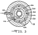
- An annular manifold 40 is positioned to surround the fiber chute 34.
- the manifold is supplied with a fluid via inlet conduit 42 which extends through the nozzle wall 20.
- the fluid can be any material suitable for affecting the path of travel of the fibers in the nozzle.
- a preferred fluid is air, but other gases or even liquids can be used. Some of the alternate fluids could be adapted to provide surface treatments or other fiber quality-affecting enhancements.
- the temperature and moisture content of the fluid can be set to positively affect the fiber quality and properties. Varying the temperature of the air might affect the density of the air.
- a preferred pressure of the fluid, as measured in the inlet conduit immediately before entering the nozzle and manifold is within the range of from about 1 to about 10 bar, although other pressures can be used.
- the fluid is discharged through discharge passageways 44 to introduce the fluid into the nozzle 18.
- discharge passageways 44 can be any number of discharge passageways 44 used.
- the discharge passageways 44 can be tangent to the annular slot 50.
- the discharge passageways can be oriented at any angle 46 within the range of from about 45 to about 90 (i.e., tangent) degrees to a radius 48 of the nozzle, as shown in the partially cut away portion in Fig. 3.
- the orientation of the discharge passageways 44 at a tangent to the radius 48 of the nozzle means that the fluid is introduced into the nozzle in a circumferential direction with respect to the longitudinal axis 36. This creates a vortex of swirling air, as indicated by directional arrow 52, surrounding the discrete length reinforcement fibers 32.
- the vortex travels down the length of the nozzle, toward the bottom 24.
- the effect of the vortex or swirling air is to cause the fibers 32 traveling inside the nozzle to disperse into a wider stream. As the fibers exit the nozzle, the flow 54 of the fibers is made wider by the action of the vortex.
- the spread or angle 56 of the flow of fibers 54 can be approximated by comparing a line 58 generally parallel to the outer periphery of the flow 54 of fibers with a line 60 parallel to the longitudinal axis 36 of the nozzle.
- the angle 56 of the flow of fibers is a function, in part, of the effect of the vortex on the fibers. Therefore, the flow of fibers dispensed from the nozzle can be controlled by controlling the fluid entering the nozzle. For example, if the flow 54 of fibers has an angle of flow 56 of about 10 degrees occurring without the introduction of any fluid, establishing the introduction of fluid through the manifold 40 and slot 50 in the manner disclosed might increase the angle of flow to about 30 degrees.
- the deposition of reinforcement fibers on the collecting surface can be significantly controlled.
- a further level of sophistication can be achieved by coordinating the flow of fluid into the nozzle with the movement of the articulation arm 12 of the dispenser. Both the fluid and the articulation arm can be moved according to patterns to create preforms having desired characteristics. As an example, if a particular area of the preform requires a higher than normal concentration of chopped reinforcement fiber, the fluid flow into the nozzle can be reduced during the time the nozzle is directing the fibers to that particular area, thereby reducing the angle of flow and concentrating the fibers on the specific area.
- the nozzle need not have any particular dimensions, but the diameter d of the nozzle is preferably within the range of from about 15 to about 90 mm, and most preferably within the range of from about 25 to about 50 mm.
- the length L of the nozzle is preferably within the range of from about 40 to about 200 mm, and most preferably within the range of from about 50 to about 90 mm.
- the flow angle 56 of the fibers can be measured by determining the diameter or spray pattern width D of the fiber flow at a specific distance H from the nozzle outlet 24.
- a typical ratio of distance H to width W is within the range of from about 5:1 to about 1:1, and preferably within the range of from about 5:1 to about 2:1.
- nozzle 61 can be configured so that there is no downwardly opening slot, such as slot 50 illustrated in Figs. 2 and 3. Instead, the discharge passageways 44 open up directly into the interior 22 of the nozzle 61.
- the nozzle 61 is also shown as being coupled with a fiber chute 34' and a chopper 62.
- the chopper can be any chopper suitable for chopping the continuous strand or roving 64.
- Conventional choppers are well known to those skilled in the art, and typically comprise a backup roll or cot roll 66 and a cutter roll 68 outfitted with blades 70. Typical lengths of the chopped reinforcement fibers is within the range of from about 15 to about 100 mm.
- the fiber chute 34' is preferably downwardly converging, i.e., inwardly tapered in the downward direction, at an angle within the range of from about 5 to about 20 degrees.
- the fiber chute can be provided with air escape ports 72 to enable the removal of air traveling with the fibers before the fibers reach the nozzle.
- the length of the chute C is preferably within the range of from about 0.5 to about 1.5 times the length L of the nozzle.
Landscapes
- Engineering & Computer Science (AREA)
- Mechanical Engineering (AREA)
- Chemical & Material Sciences (AREA)
- Composite Materials (AREA)
- Robotics (AREA)
- Processing And Handling Of Plastics And Other Materials For Molding In General (AREA)
- Reinforced Plastic Materials (AREA)
- Nonwoven Fabrics (AREA)
- Moulding By Coating Moulds (AREA)
Description
Claims (9)
- A method of dispensing a reinforcement strand comprising:chopping the reinforcement strand into discrete reinforcement fibers (14);directing the discrete reinforcement fibers (14) into a dispensing nozzle (18) so that the discrete reinforcement fibers (14) travel along a path extending generally along a longitudinal axis (36) of the nozzle (18);introducing a fluid into an annular manifold (40) of the nozzle (18), the fluid traveling in a circumferential direction with respect to the longitudinal axis (36), thereby creating a vortex (52) of the fluid surrounding the discrete reinforcement fibers (14) in the nozzle (18);dispensing the discrete length reinforcement fibers (14) from the nozzle (18) as a flow; andcontrolling the flow of fibers (14) dispensed from the nozzle (18) by controlling the fluid introduced into the nozzle (18).
- A method according to claim 1, in which the step of introducing the fluid into the nozzle (18) includes directing the fluid from the annular manifold (40) into an annular slot (50) that opens downwardly into a nozzle chamber (22) within the nozzle (18).
- A method according to claim 2, in which the step of introducing the fluid into the manifold (40) includes supplying the fluid at a pressure within the range of from about 1 to about 10 bar, as measured just outside the nozzle (18).
- A method according to any one of claims 1 to 3, in which the nozzle (18) has an interior portion defined by an interior wall (26) which is at an interior angle (28) to the longitudinal axis (36) of the nozzle (18), the angle being within the range of from about 0 to about 20 degrees.
- A method according to any one of claims 1 to 4, in which the step of controlling the flow of fibers (14) dispensed from the nozzle (18) includes establishing an angle (56) of the flow of the fibers (14), with respect to the longitudinal axis (36) of the nozzle (18), that is within the range of from about 10 to about 35 degrees.
- A method according to any one of claims 1 to 5, including mounting the nozzle (18) on an articulation arm (12), dispensing the discrete length reinforcement fibers (14) from the nozzle (18), and moving the nozzle (18) according to a pattern to create a reinforcement fiber preform on a collection surface (16).
- A method according to claim 6, including chopping the reinforcement strand into discrete reinforcement fibers (14) with a chopper (62) mounted on the articulation arm (12).
- A method according to claim 7, including conveying the chopped reinforcement fibers (14) from the chopper (62) to the nozzle (18) with a converging fiber chute (34).
- A method according to claim 8, including removing air traveling with the chopped reinforcement fibers (14) from the chute (34) before the chopped reinforcement fibers reach the nozzle (18).
Applications Claiming Priority (3)
| Application Number | Priority Date | Filing Date | Title |
|---|---|---|---|
| US09/044,638 US6029897A (en) | 1998-03-19 | 1998-03-19 | Method of dispensing chopped reinforcement strand using a vortex nozzle |
| US44638 | 1998-03-19 | ||
| PCT/EP1999/001279 WO1999047342A1 (en) | 1998-03-19 | 1999-02-23 | Method of dispensing chopped reinforcement strand using a vortex nozzle |
Publications (2)
| Publication Number | Publication Date |
|---|---|
| EP1077805A1 EP1077805A1 (en) | 2001-02-28 |
| EP1077805B1 true EP1077805B1 (en) | 2002-08-21 |
Family
ID=21933475
Family Applications (1)
| Application Number | Title | Priority Date | Filing Date |
|---|---|---|---|
| EP99910297A Expired - Lifetime EP1077805B1 (en) | 1998-03-19 | 1999-02-23 | Method of dispensing chopped reinforcement strand using a vortex nozzle |
Country Status (8)
| Country | Link |
|---|---|
| US (1) | US6029897A (en) |
| EP (1) | EP1077805B1 (en) |
| JP (1) | JP2002506754A (en) |
| KR (1) | KR20010041956A (en) |
| AU (1) | AU2930499A (en) |
| CA (1) | CA2323491A1 (en) |
| DE (1) | DE69902583T2 (en) |
| WO (1) | WO1999047342A1 (en) |
Families Citing this family (17)
| Publication number | Priority date | Publication date | Assignee | Title |
|---|---|---|---|---|
| AU2002360725A1 (en) * | 2001-12-31 | 2003-07-24 | Owens Corning | Method for producting lofty, acoustical and structural parts |
| US20080122134A1 (en) * | 2002-12-24 | 2008-05-29 | Michael Rajendran S | Headliners, door panels and interior trim parts that are lofty, acoustical and structural |
| US8028736B2 (en) * | 2006-08-25 | 2011-10-04 | Ocv Intellectual Capital, Llc | System for forming reinforcement layers having cross-directionally oriented fibers |
| GB0623047D0 (en) * | 2006-11-18 | 2006-12-27 | Bentley Motors Ltd | A moulded product and method of producing it |
| DE102007008391A1 (en) * | 2007-02-21 | 2008-08-28 | J.H. Ziegler Gmbh & Co. Kg | Making three-dimensional pressed molding from fibrous agglomerate, introduces material into mold in fluid flow and applies mechanical compression |
| DE102007008390A1 (en) * | 2007-02-21 | 2008-08-28 | J.H. Ziegler Gmbh & Co. Kg | Producing embossed molding from agglomerate, e.g. fibrous strand, includes supplying agglomerate into mold chamber, using carrier medium, via inlet supplied by separate lines |
| US8474115B2 (en) * | 2009-08-28 | 2013-07-02 | Ocv Intellectual Capital, Llc | Apparatus and method for making low tangle texturized roving |
| EP2727694B1 (en) * | 2012-11-05 | 2015-01-28 | Toho Tenax Europe GmbH | Deposition device for controlled lowering of reinforcement fibre bundles |
| EP2727693B1 (en) * | 2012-11-05 | 2015-01-14 | Toho Tenax Europe GmbH | Method for manufacturing fibre preforms |
| US20150258762A1 (en) * | 2014-03-14 | 2015-09-17 | Teijin Limited | Method of Producing Isotropic Random Mat for Forming Thermoplastic Composite Material |
| US10160004B2 (en) * | 2015-07-07 | 2018-12-25 | Palo Alto Research Center Incorporated | Creating aligned and oriented fiber reinforced polymer composites |
| EP3408434B1 (en) * | 2016-01-26 | 2025-06-25 | Continental Structural Plastics, Inc. | Process and system of debundling fiber tow for use in preform mats and molding compositions containing such fibers |
| US11072092B2 (en) * | 2016-11-30 | 2021-07-27 | Continental Structural Plastics | Blended fiber mat formation for structural applications |
| EP3548238B1 (en) * | 2016-11-30 | 2021-11-03 | Continental Structural Plastics, Inc. | Dispersed fiber mat formation |
| US11642815B2 (en) * | 2016-11-30 | 2023-05-09 | Teijin Automotive Technologies, Inc. | Fiber mat formation for structural applications |
| JP2018149730A (en) * | 2017-03-13 | 2018-09-27 | 東レエンジニアリング株式会社 | Fiber bundle sticking device |
| US11035134B2 (en) | 2017-10-27 | 2021-06-15 | Owens Corning Intellectual Capital, Llc | Systems for and methods of conditioning loosefill insulation material |
Family Cites Families (29)
| Publication number | Priority date | Publication date | Assignee | Title |
|---|---|---|---|---|
| US3126157A (en) * | 1964-03-24 | |||
| US2810157A (en) * | 1952-03-05 | 1957-10-22 | Owens Corning Fiberglass Corp | Method and apparatus for producing fibers |
| AT226951B (en) * | 1955-09-28 | 1963-04-25 | Cimex Trust Reg | Method and spray device for producing layers of shell-like molded parts |
| US3034213A (en) * | 1960-06-15 | 1962-05-15 | Gaymond E Milligan | Roving cutter |
| US3170197A (en) * | 1961-01-12 | 1965-02-23 | Ivan G Brenner | Apparatus for producing a fibrous glass preform |
| US3249307A (en) * | 1962-10-16 | 1966-05-03 | Vilbiss Co | Apparatus for spraying fibers and resinous materials |
| US3831879A (en) * | 1970-03-11 | 1974-08-27 | Us Navy | Wire dispenser |
| US3719540A (en) * | 1970-05-04 | 1973-03-06 | Hercules Inc | Preparation of transversely fibrillated film |
| US3977069A (en) * | 1974-12-18 | 1976-08-31 | Brunswick Corporation | Process and apparatus for production of precision cut lengths of metal wires and fibers |
| US4001935A (en) * | 1975-06-12 | 1977-01-11 | Binks Manufacturing Company | Roving cutter |
| NL7802576A (en) * | 1977-05-13 | 1978-11-15 | Neumuenster Masch App | METHOD AND DEVICE FOR TREATING FIBER TIRES. |
| CA1110817A (en) * | 1978-02-23 | 1981-10-20 | Atlantic Bridge Company Limited | Fibre reinforced plastic structures and method and apparatus for producing same |
| US4178670A (en) * | 1978-06-22 | 1979-12-18 | Crystal Systems, Inc. | Process of forming a wire pack |
| US4487365A (en) * | 1981-05-19 | 1984-12-11 | Sperber Henry V | Reduced fiber insulation nozzle |
| US4519281A (en) * | 1983-03-07 | 1985-05-28 | Eastman Kodak Company | Package wind cutter |
| US4750960A (en) * | 1984-09-10 | 1988-06-14 | Rensselaer Polytechnic Institute | Robotic winding system and method |
| US4630515A (en) * | 1985-10-15 | 1986-12-23 | Eastman Kodak Company | Apparatus for cutting continuous strand |
| US5192390A (en) * | 1987-11-13 | 1993-03-09 | Bridgestone/Firestone Inc. | Mandrel means |
| US4917298A (en) * | 1988-12-05 | 1990-04-17 | Usbi Company | Method for spraying a fiber-containing fluid mixture using an air atomizing spray gun |
| US5020403A (en) * | 1989-06-20 | 1991-06-04 | Angelo Joseph J D | Web feeding, cutting and dispensing machine |
| SU1694724A1 (en) * | 1989-08-02 | 1991-11-30 | Предприятие П/Я А-7317 | Device for cutting threads to size |
| US4944446A (en) * | 1989-11-02 | 1990-07-31 | Micron Technology, Inc. | Automatic preform dispenser |
| US5192387A (en) * | 1990-11-05 | 1993-03-09 | The C.A. Lawton Company | Method of making preforms |
| US5158631A (en) * | 1991-01-15 | 1992-10-27 | United Technologies Corporation | Method of manufacturing a dog-leg shaped ply of composite material and the tool used in carrying out the method |
| US5093059A (en) * | 1991-01-18 | 1992-03-03 | Shell Oil Company | Method for the transport of a homogeneous mixture of chopped fibers |
| US5131590A (en) * | 1991-08-13 | 1992-07-21 | Henry Sperber | Fibrous sprayed insulation having homogeneous density |
| US5204033A (en) * | 1991-10-21 | 1993-04-20 | Brunswick Corporation | Method of fabricating a preform in a resin transfer molding process |
| US5463919A (en) * | 1991-11-02 | 1995-11-07 | Zortech International Limited | Apparatus for cutting wound coils |
| US5262106A (en) * | 1992-02-06 | 1993-11-16 | The United States Of America As Represented By The United States Department Of Energy | Anisotropic fiber alignment in composite structures |
-
1998
- 1998-03-19 US US09/044,638 patent/US6029897A/en not_active Expired - Fee Related
-
1999
- 1999-02-23 AU AU29304/99A patent/AU2930499A/en not_active Abandoned
- 1999-02-23 WO PCT/EP1999/001279 patent/WO1999047342A1/en not_active Ceased
- 1999-02-23 CA CA002323491A patent/CA2323491A1/en not_active Abandoned
- 1999-02-23 JP JP2000536559A patent/JP2002506754A/en active Pending
- 1999-02-23 DE DE69902583T patent/DE69902583T2/en not_active Expired - Fee Related
- 1999-02-23 EP EP99910297A patent/EP1077805B1/en not_active Expired - Lifetime
- 1999-02-23 KR KR1020007010274A patent/KR20010041956A/en not_active Withdrawn
Also Published As
| Publication number | Publication date |
|---|---|
| AU2930499A (en) | 1999-10-11 |
| DE69902583T2 (en) | 2003-05-22 |
| WO1999047342A1 (en) | 1999-09-23 |
| CA2323491A1 (en) | 1999-09-23 |
| KR20010041956A (en) | 2001-05-25 |
| DE69902583D1 (en) | 2002-09-26 |
| US6029897A (en) | 2000-02-29 |
| EP1077805A1 (en) | 2001-02-28 |
| JP2002506754A (en) | 2002-03-05 |
Similar Documents
| Publication | Publication Date | Title |
|---|---|---|
| US6029897A (en) | Method of dispensing chopped reinforcement strand using a vortex nozzle | |
| EP2073975B1 (en) | System for forming reinforcement layers having cross-directionally oriented fibers | |
| US3170197A (en) | Apparatus for producing a fibrous glass preform | |
| US3504861A (en) | Means for spraying fibers and resinous material | |
| EP0907475B1 (en) | Method for dispensing resinated reinforcement fibers | |
| US5819614A (en) | Method for dispensing reinforcement fibers | |
| US3177275A (en) | Method and means for producing fibrous articles | |
| AU655223B2 (en) | Method and apparatus for the transport of a homogeneous mixture of chopped fibers | |
| EP1204789B1 (en) | Method of forming discrete length fibers | |
| CA2050200A1 (en) | Method and apparatus for producing mold charge blanks for molding processes | |
| US5688467A (en) | Apparatus and method for fabricating a preform having a narrow channel flange | |
| EP1144288A3 (en) | Method for dispensing reinforcement fibers | |
| MXPA00009148A (en) | Method of dispensing chopped reinforcement strand using a vortex nozzle | |
| US3414424A (en) | Method for spraying fibers and resinous materials | |
| WO2002026391A1 (en) | Dispensing chopped reinforcement strand using oriented dispensing nozzles | |
| US4923731A (en) | Novel preform screens and preform product | |
| WO1991012944A1 (en) | Apparatus and method for applying preform fibers | |
| JPH09300476A (en) | Production of spray molded article of fiber reinforced resin | |
| JPH07100828A (en) | Process for producing mixture of reinforcing fiber and resin powder, sheet and molded body | |
| MXPA98010297A (en) | Method for distributing resin reinforcement fibers |
Legal Events
| Date | Code | Title | Description |
|---|---|---|---|
| PUAI | Public reference made under article 153(3) epc to a published international application that has entered the european phase |
Free format text: ORIGINAL CODE: 0009012 |
|
| 17P | Request for examination filed |
Effective date: 20001017 |
|
| AK | Designated contracting states |
Kind code of ref document: A1 Designated state(s): DE FR GB IT |
|
| GRAG | Despatch of communication of intention to grant |
Free format text: ORIGINAL CODE: EPIDOS AGRA |
|
| 17Q | First examination report despatched |
Effective date: 20011115 |
|
| GRAG | Despatch of communication of intention to grant |
Free format text: ORIGINAL CODE: EPIDOS AGRA |
|
| GRAH | Despatch of communication of intention to grant a patent |
Free format text: ORIGINAL CODE: EPIDOS IGRA |
|
| GRAH | Despatch of communication of intention to grant a patent |
Free format text: ORIGINAL CODE: EPIDOS IGRA |
|
| GRAA | (expected) grant |
Free format text: ORIGINAL CODE: 0009210 |
|
| RIN1 | Information on inventor provided before grant (corrected) |
Inventor name: JANDER, MICHAEL, H. |
|
| AK | Designated contracting states |
Kind code of ref document: B1 Designated state(s): DE FR GB IT |
|
| RAP1 | Party data changed (applicant data changed or rights of an application transferred) |
Owner name: OWENS CORNING COMPOSITES S.P.R.L. |
|
| REG | Reference to a national code |
Ref country code: GB Ref legal event code: FG4D |
|
| REF | Corresponds to: |
Ref document number: 69902583 Country of ref document: DE Date of ref document: 20020926 |
|
| ET | Fr: translation filed | ||
| PG25 | Lapsed in a contracting state [announced via postgrant information from national office to epo] |
Ref country code: GB Free format text: LAPSE BECAUSE OF NON-PAYMENT OF DUE FEES Effective date: 20030223 |
|
| PLBE | No opposition filed within time limit |
Free format text: ORIGINAL CODE: 0009261 |
|
| STAA | Information on the status of an ep patent application or granted ep patent |
Free format text: STATUS: NO OPPOSITION FILED WITHIN TIME LIMIT |
|
| 26N | No opposition filed |
Effective date: 20030522 |
|
| PG25 | Lapsed in a contracting state [announced via postgrant information from national office to epo] |
Ref country code: DE Free format text: LAPSE BECAUSE OF NON-PAYMENT OF DUE FEES Effective date: 20030902 |
|
| GBPC | Gb: european patent ceased through non-payment of renewal fee | ||
| PG25 | Lapsed in a contracting state [announced via postgrant information from national office to epo] |
Ref country code: FR Free format text: LAPSE BECAUSE OF NON-PAYMENT OF DUE FEES Effective date: 20031031 |
|
| REG | Reference to a national code |
Ref country code: FR Ref legal event code: ST |
|
| PG25 | Lapsed in a contracting state [announced via postgrant information from national office to epo] |
Ref country code: IT Free format text: LAPSE BECAUSE OF NON-PAYMENT OF DUE FEES Effective date: 20050223 |