EP1077577A1 - Radio receiver and received power amplifying method - Google Patents
Radio receiver and received power amplifying method Download PDFInfo
- Publication number
- EP1077577A1 EP1077577A1 EP00906652A EP00906652A EP1077577A1 EP 1077577 A1 EP1077577 A1 EP 1077577A1 EP 00906652 A EP00906652 A EP 00906652A EP 00906652 A EP00906652 A EP 00906652A EP 1077577 A1 EP1077577 A1 EP 1077577A1
- Authority
- EP
- European Patent Office
- Prior art keywords
- users
- received signal
- communication state
- transmission apparatus
- radio transmission
- Prior art date
- Legal status (The legal status is an assumption and is not a legal conclusion. Google has not performed a legal analysis and makes no representation as to the accuracy of the status listed.)
- Withdrawn
Links
Images


Classifications
-
- H—ELECTRICITY
- H04—ELECTRIC COMMUNICATION TECHNIQUE
- H04W—WIRELESS COMMUNICATION NETWORKS
- H04W52/00—Power management, e.g. Transmission Power Control [TPC] or power classes
- H04W52/04—Transmission power control [TPC]
- H04W52/30—Transmission power control [TPC] using constraints in the total amount of available transmission power
- H04W52/34—TPC management, i.e. sharing limited amount of power among users or channels or data types, e.g. cell loading
- H04W52/346—TPC management, i.e. sharing limited amount of power among users or channels or data types, e.g. cell loading distributing total power among users or channels
-
- H—ELECTRICITY
- H04—ELECTRIC COMMUNICATION TECHNIQUE
- H04W—WIRELESS COMMUNICATION NETWORKS
- H04W52/00—Power management, e.g. Transmission Power Control [TPC] or power classes
- H04W52/04—Transmission power control [TPC]
- H04W52/30—Transmission power control [TPC] using constraints in the total amount of available transmission power
- H04W52/34—TPC management, i.e. sharing limited amount of power among users or channels or data types, e.g. cell loading
- H04W52/343—TPC management, i.e. sharing limited amount of power among users or channels or data types, e.g. cell loading taking into account loading or congestion level
Definitions
- the present invention relates to a radio reception apparatus and received power amplification method.
- FIG. 1 is a block diagram illustrating a configuration of a conventional radio reception apparatus employed for a communication in which a CDMA system is utilized.
- a radio reception apparatus 10 a signal received by an antenna 11 is subjected to predetermined radio processing at a radio unit 12, before being outputted to an amplifier 13.
- the amplifier 13 outputs a signal indicating a power value of a received signal to a controller 14.
- the controller 14 calculates an amplification factor from the power value of the received signal and a target power value so that the power value of signal outputted to matched filters 15, 16, and 17 from the amplifier 13 comes into constant value in conformity with the target power value. Then the controller 14 performs feedback of a control signal instructing the amplification factor to the amplifier 13.
- the amplifier 13 amplifies power of a received signal in accordance with the amplification factor undergoing the feedback, thus, outputting the amplified signal to the matched filters 15, 16, and 17.
- the power value of the received signal outputted to the controller 14 from the amplifier 13 employs an average value being average over a predetermined time interval in order to relieve an influence of a noise. Further, in the case where the radio reception apparatus 10 receives signals transmitted from a plurality of radio transmission apparatus, a power value of a received signal outputted to the controller 14 from the amplifier 13 comes into a power value of the received signal which is subjected to code division multiplexing.
- the matched filters 15, 16, and 17 each gives despreading processing to an amplified signal, thus, calculating correlation value between the amplified signal and spreading code to output to demodulators 18, 19, and 20 respectively.
- the demodulators 18, 19, and 20 each gives predetermined demodulation processing to the amplified signals on the basis of the respective correlation values to output demodulated signals to A/D converter and so forth at latter stages.
- inter-communication user in the case where there exists users who do not transmit signals actually because the users have no data to be transmitted in an interval (hereinafter referred to as inter-communication user) in a plurality of radio transmission apparatus users who are in communication with the radio reception apparatus, the number of signals which are subjected to code division multiplexing become smaller than that in the case where the whole users transmit signals during this interval.
- an average value of the power value of the received signal outputted from the amplifier 13 to the controller 14 becomes smaller value than that in the case where the whole users transmit the signals.
- the controller 14 calculates an amplification factor from the average value of the smaller value and the target power value, and therefore, the amplification factor becomes lager than that in the case where the whole users transmit the signals.
- inter-transmission user a user who transmits signals actually to a radio reception apparatus while being provided with data to be transmitted in a plurality of radio transmission apparatus users.
- data to be transmitted means voice data, image data and so forth, to be transmitted from a radio transmission apparatus
- to transmit signals actually means to transmit signals of voice data, image data and so forth except control signals.
- the present inventor notes that the power value of the amplified signal exceeding the target power value is caused by the matter that an amplification factor is calculated on the basis of only the power value of the received signal.
- an amplification factor is calculated on the basis of only the power value of the received signal.
- the radio reception apparatus calculates a power value of a received signal per one person of inter-transmission users from both of a power value of the received signal and the number of the inter-transmission users, thus estimating a power value in the case where the whole inter-communication users come into inter-transmission users.
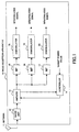
- FIG. 2 is a block diagram illustrating a configuration of a radio reception apparatus according to the embodiment 1 of the present invention.
- a radio reception apparatus 100 signals received by an antenna 101 are subjected to predetermined radio processing at a radio unit 102, before being outputted to an amplifier 103.
- signals received by the antenna 101 are signals which are subjected to spreading with respective spreading codes whose spreading factors are equal to each other, and then multiplexing.
- the amplifier 103 outputs a signal indicating a power value of a received signal to a controller 104.
- the controller 104 calculates an amplification factor in accordance with a calculation method described later so that the power value of the signal outputted to matched filters 105, 106, and 107 from the amplifier 103 become constant in conformity with a target power value.
- the controller 104 performs feedback of a control signal instructing an amplification factor to the amplifier 103.
- the amplifier 103 amplifies power of a received signal in accordance with the amplification factor undergoing feedback, then, outputting the amplified signal to the matched filters 105, 106, and 107.
- the power value of the received signal outputted to the controller 104 from the amplifier 103 employs average value being averaged over a predetermined time interval in order to relieve an influence of a noise. Further, in the case where the radio reception apparatus 100 receives signals transmitted from a plurality of radio transmission apparatus, a power value of a received signal outputted to the controller 104 from the amplifier 103 comes into a power value of the received signal which is subjected to code division multiplexing.
- the matched filters 105, 106, and 107 each gives despreading processing to an amplified signal, before calculating a correlation value between the amplified signal and a spreading code to output to demodulators 108, 109, and 110 respectively.
- the demodulators 108, 109, and 110 each gives predetermined demodulation processing to the amplified signal on the basis of these correlation values, before outputting a demodulated signal to A/D converter and so forth at the latter stage while outputting the demodulated signal to judgement units 111, 112, and 113 respectively.
- the judgement units 111, 112, and 113 judge whether each radio transmission apparatus user is an inter-transmission user or an inter-communication user in accordance with a method touched upon later. Then, in the case where the radio transmission apparatus user is the inter-transmission user, the judgement units 111, 112, and 113 each outputs a signal indicating that the user is an inter-transmission user to the controller 104.
- step (hereinafter, referred to as ST) 201 the number of inter-transmission users is specified.
- the specification of the number of the inter-transmission users is executed in accordance with, for instance, the following procedure.
- Demodulated signals demodulated in the demodulators 108, 109, and 110 are outputted to the judgement units 111,112, and 113 respectively.
- the judgement units 111, 112, and 113 judge whether each radio transmission apparatus user is an inter-transmission user or an inter-communication user in accordance with respective demodulated signals.
- the judgement units 111, 112, and 113 output signals each indicating that the user is an inter-transmission user to the controller 104.
- the controller 104 specifies the number of signals indicating that the user is an inter-transmission user as the number of the inter-transmission user.
- each radio transmission apparatus user is an inter-transmission user or an inter-communication user, is executed in accordance with, for instance, the following method. Namely, a predetermined threshold value for amplitude of a demodulated signal is set in the judgement units 111, 112, and 113.
- the threshold value of the amplitude is set in such a way that, for instance, a power value of a signal transmitted by every one person of the inter-transmission user is a reference value.
- the judgement units 111, 112, and 113 compare the predetermined threshold value with amplitude of the demodulated signals demodulated actually in the demodulators 108, 109, and 110, respectively. In the case where the amplitude of the demodulated signals demodulated actually exceeds the predetermined threshold value, the judgement units 111, 112, and 113 each judges that the radio transmission apparatus user who transmits the demodulated signal is an inter-transmission user. According to the judgement method, it is possible to judge a radio transmission apparatus user who is in the state of transmitting a signal such as voice data, image data actually as an inter-transmission user.
- a judgement method is not particularly limited to the above method, and another method is also usable.
- received power per one user is calculated.
- the controller 104 calculates a power value of a received signal per one person of the inter-transmission users from both of the power value of the received signal outputted from the amplifier 103 and the number of the inter-transmission users specified-above. Namely, the controller 104 divides the power value of the received signal by the number of the inter-transmission users specified-above. The controller 104 sets the obtained result of this division to the power value of the received signal per one person of the inter-transmission user.
- received power for the whole users is calculated.
- the controller 104 calculates power values (hereinafter referred to as "received power value for the whole users") of signals which the radio reception apparatus 100 receives, in the case where the whole of the inter-communication users come into inter-transmission users, from both of the power value of the received signal per one person of the inter-transmission users calculated-above and a signal indicating the number of the inter-communication users outputted from predetermined portion within the radio reception apparatus 100. Namely, the controller 104 multiplies the power value of the received signal per one person of the inter-transmission user by the number of the inter-communication users. The controller 104 sets the obtained multiplication result to the received power value for the whole users.
- the controller 104 calculates an amplification factor so that the received power value for the whole users calculated above comes into a target power value set in the controller 104 beforehand.
- the radio reception apparatus and the received power amplification method of the present embodiment even when the number of inter-transmission users who are in the state of transmitting signals actually increase, it is possible to calculate an appropriate amplification factor so that a power value of an amplified signal does not exceed a target power value. Accordingly, it is possible to prevent the increase of a processing load on the A/D converter and so forth in the radio reception apparatus.
- FIG. 4 is a block diagram illustrating a configuration of a radio reception apparatus according to the embodiment 2 of the present invention. However, in FIG. 4, the same number is added to about the same configuration / operation as that of FIG. 2 to omit the description.
- a controller 301 calculates an amplification factor in accordance with a calculation method described later so that the power value of the signal outputted to matched filters 302, 303, and 304 from the amplifier 103 become a constant in conformity with a target power value.
- the controller 301 performs feedback of a control signal instructing the amplification factor to the amplifier 103.
- the matched filters 302, 303, and 304 each executes despreading processing with respective spreading factors which are different from each other set in the respective matched filters.
- spreading factors to be set are fixed spreading factors.
- the spreading factors are not limited to the fixed spreading factor.
- the spreading factors to be set may be variable, for instance, on the basis of spreading factor information.
- the matched filters 302, 303, and 304 each gives despreading processing to an amplified signal with the respective spreading codes of the spreading factors set previously.
- the matched filters 302, 303, and 304 each calculates a correlation value between the amplified signal and the spreading code, and output the correlation value to the demodulators 108, 109, and 110 respectively.
- the spreading factors set in the matched filters 302, 303,and 304 are taken to be A, B, and C respectively.
- the spreading factor B is two times as large as the spreading factor A
- the spreading factor C is two times as large as the spreading factor B.
- the number of inter-communication users is three.
- the spreading factors (spreading factor of the inter-communication user) inputted to the controller 301 as spreading factor information is A, B, or C.
- the inter-transmission user is one, who transmits signals with the spreading factor B.
- an inter-transmission user is specified.
- the matched filters 302, 303, and 304 each gives despreading processing to the amplified signal, and output a correlation value to demodulators 108, 109, and 110 respectively.
- the demodulated signals demodulated in the demodulators 108, 109, and 110 are outputted to the judgement units 111, 112, and 113 respectively.
- the judgement units 111, 112, and 113 judge whether each radio transmission apparatus user is an inter-transmission user or an inter-communication user while employing the demodulated signals in accordance with the method described in the embodiment 1. In the case where the radio transmission apparatus user is the inter-transmission user, the judgement units 111, 112, and 113 output signals each indicating that the user is the inter-transmission user to the controller 301.
- the controller 301 observes which judgement unit outputs the signal indicating that the user is an inter-transmission user.
- the controller 301 specifies the inter-transmission user by specifying the judgement unit which outputs a signal indicating that the user is an inter-transmission user.
- the amplitude of the demodulated signal being subjected to despreading processing at the matched filter 303 in which the spreading factor B is set exceeds the threshold value. Further, amplitude of the demodulated signals outputted to the other judgement units 111 and 113 except the judgement unit 112, does not exceed the threshold value.
- the controller 301 specifies that the judgement unit which outputs a signal indicating that the user is an inter-transmission user is the judgement unit 112. Namely, the controller 301 specifies that the user who transmits signals with the spreading factor B is a inter-transmission user.
- the converted number of users is calculated.
- a communication quality deteriorates due to a low spreading factor.
- the communication system controls signals so as to enlarge power values of signals with respect to signals with low spreading factors. Due to this control, an energy of a signal per one bit is kept constant, thus, the communication quality is stabilized. For instance, in the case where the communication system makes the spreading factor of a signal is 1/2 times as large as that of the original spreading factor, the communication system makes the power value of the signal 2 times as large as that of the original power value.
- the power value of the signal with the spreading factor C being set to a reference is taken to be 1 (one)
- the power value of the signal with the spreading factor B comes into 2 (two)
- the power value of the signal with the spreading factor A comes into 4 (four).
- a power value of a signal per one bit is replaced by the number of users. So, the power value of the signal with the spreading factor C corresponds to one person.
- the power value of the signal with the spreading factor B corresponds to two persons.
- the power value of the signal with the spreading factor A corresponds to four persons.
- the controller 301 converts the power value into the number of persons in accordance with the spreading factors (spreading factor of the inter-communication user) A, B, and C inputted to the controller 301 by way of the spreading factor information. Then the controller 301 calculates that the number of the inter-communication users is seven. Further, the controller 301 converts the power value into the number of persons in accordance with specified result of the inter-transmission user of ST 401(specified result that the users who transmit signals with the spreading factors B are a specified to be the inter-transmission users). Then the controller 301 calculates that the number of the inter-transmission users is two.
- received power per one user is calculated.
- the controller 301 calculates a power value of a received signal per one person of the inter-transmission users from both of the power value of the received signal outputted from the amplifier 103 and the number of the inter-transmission users calculated-above. Namely, the controller 301 divides the power value of the received signal by the number of the inter-transmission users calculated-above. The controller 301 sets the obtained result of this division to the power value of the received signal per one person of the inter-transmission user.
- received power for the whole users is calculated.
- the controller 301 calculates a received power value for the whole users from both of the power value of the received signal per one person of the inter-transmission user calculated-above and the number of the inter-communication users calculated-above. Namely, the controller 301 multiplies the power value of the received signal per one person of the inter-transmission user by the number of the inter-communication users. The controller 301 sets the obtained multiplication result to the received power value for the whole users.
- the controller 301 calculates an amplification factor so that the received power value for the whole users calculated-above comes into a target power value set in the controller 301 beforehand.
- the spreading factor is set to A, B, or C.
- the spreading factor B is set to 2 times the spreading factor A, furthermore, the spreading factor C is set to 2 times the spreading factor B.
- more kinds of spreading factor are usable to be employed.
- a relationship between respective spreading factors is not limited to the relationship described-above.
- the converted number of users is calculated on the basis of the matter that when the spreading factors are different, the power values of the received signals are also different. However, even when spreading factors are equal, the received power values are different in accordance with the difference between required communication qualities. Consequently, in this case, the converted number of users is calculated while employing both of the spreading factor and the communication quality.
- the radio reception apparatus and the received power amplification method of the present embodiment even when signals multiplexed in the received signals are subjected to spreading with a plurality of spreading factors and further the number of inter-transmission users who are in the state of transmitting signals actually increase, it is possible to calculate an appropriate amplification factor so that a power value of an amplified signal does not exceed a target power value. Accordingly, it is possible to prevent the increase of a processing load on the A/D converter and so forth in the radio reception apparatus.
- radio reception apparatus of the embodiment land the embodiment 2
- respective three matched filters, three demodulators, and three judgement units are provided for the radio reception apparatus.
- a configuration of the radio reception apparatus is not limited to the above.
- the radio reception apparatus may be provided with each at least, one matched filter, one demodulator, and one judgement unit.
- the number of inter-communication users and the number of inter-transmission users are not limited.
- the present invention is applicable to a base station apparatus employed in a radio communication system, and / or a communication terminal apparatus such as mobile station which performs radio communication with the base station apparatus.
Landscapes
- Engineering & Computer Science (AREA)
- Computer Networks & Wireless Communication (AREA)
- Signal Processing (AREA)
- Mobile Radio Communication Systems (AREA)
- Circuits Of Receivers In General (AREA)
Abstract
Description
Claims (8)
- A radio reception apparatus comprising:a judgement unit for judging radio transmission apparatus users as being in a second communication state in which the users transmits signals actually, from among radio transmission apparatus users each in a first communication state in which the users are in communication with a radio reception apparatus;a controller for changing an amplification factor for a received signal in accordance with a judgement result; andan amplifier for amplifying the received signal in accordance with a changed amplification factor.
- A radio reception apparatus according to claim 1, wherein the judgement unit compares an amplitude value of the received signal with a predetermined threshold value, and in the case where the amplitude value exceeds the threshold value, the judgement unit judges a radio transmission apparatus user who transmits the received signal as a radio transmission apparatus user who is in the second communication state.
- A radio reception apparatus according to claim 1, wherein the controller divides an intensity of the received signal by the number of radio transmission apparatus users each in the second communication state, then, the controller multiplies a value obtained from the division by the number of radio transmission apparatus users each in the first communication state, whereby the controller estimates an intensity of the received signal in the case where all the members of radio transmission apparatus users being in the first communication state come into the second communication state, and thus, the controller changes the amplification factor on the basis of a estimation result.
- A radio reception apparatus according to claim 1, wherein the controller divides an intensity of the received signal by the number of radio transmission apparatus users each in the first communication state, the number being calculated using a spreading factor of a signal which is multiplexed in the received signal, then, the controller multiplies a value obtained from the division by the number of radio transmission apparatus users each in the second communication state, the number being calculated using the spreading factor, whereby the controller estimates an intensity of the received signal in the case where all the members of radio transmission apparatus users being in the first communication state come into the second communication state, and thus, the controller changes the amplification factor on the basis of a estimation result.
- A base station apparatus mounted with a radio reception apparatus, the radio reception apparatus comprising:a judgement unit for judging radio transmission apparatus users as being in a second communication state in which the users transmits signals actually, from among radio transmission apparatus users each in a first communication state in which the users are in communication with a radio reception apparatus;a controller for changing an amplification factor for a received signal in accordance with a judgement result; andan amplifier for amplifying the received signal in accordance with a changed amplification factor.
- A communication terminal apparatus mounted with a radio reception apparatus, the radio reception apparatus comprising:a judgement unit for judging radio transmission apparatus users as being in a second communication state in which the users transmits signals actually, from among radio transmission apparatus users each in a first communication state in which the users are in communication with a radio reception apparatus;a controller for changing an amplification factor for a received signal in accordance with a judgement result; andan amplifier for amplifying the received signal in accordance with a changed amplification factor.
- A received power amplification method comprising:a judgement step of judging radio transmission apparatus users as being in a second communication state in which the users transmits signals actually, from among radio transmission apparatus users each in a first communication state in which the users are in communication with a radio reception apparatus;a control step of changing an amplification factor for a received signal in accordance with a judgement result; andan amplification step of amplifying the received signal in accordance with a changed amplification factor,
wherein in the control step, an intensity of the received signal is divided by the number of radio transmission apparatus users each in the second communication state, then, a value obtained from the division is multiplied by the number of radio transmission apparatus users each in the first communication state, whereby an intensity of the received signal is estimated which is to be obtained in the case where all the members of radio transmission apparatus users being in the first communication state come into the second communication state, and thus, the amplification factor is changed on the basis of a estimation result. - A received power amplification method comprising:a judgement step of judging radio transmission apparatus users as being in a second communication state in which the users transmits signals actually, from among radio transmission apparatus users each in a first communication state in which the users are in communication with a radio reception apparatus;a control step of changing an amplification factor for a received signal in accordance with a judgement result; andan amplification step of amplifying the received signal in accordance with a changed amplification factor,
wherein in the control step, an intensity of the received signal is divided by the number of radio transmission apparatus users each in the first communication state, the number being calculated using a spreading factor of a signal which is multiplexed in the received signal, then, a value obtained from the division is multiplied by the number of radio transmission apparatus users each in the second communication state, the number being calculated using the spreading factor, whereby an intensity of the received signal is estimated which is to be obtained in the case where all the members of radio transmission apparatus users being in the first communication state come into the second communication state, and thus, the amplification factor is changed on the basis of a estimation result.
Applications Claiming Priority (3)
| Application Number | Priority Date | Filing Date | Title |
|---|---|---|---|
| JP10304599 | 1999-03-06 | ||
| JP10304599A JP2000261375A (en) | 1999-03-06 | 1999-03-06 | Wireless receiver and received power amplification method |
| PCT/JP2000/001255 WO2000054528A1 (en) | 1999-03-06 | 2000-03-03 | Radio receiver and received power amplifying method |
Publications (2)
| Publication Number | Publication Date |
|---|---|
| EP1077577A1 true EP1077577A1 (en) | 2001-02-21 |
| EP1077577A4 EP1077577A4 (en) | 2005-11-16 |
Family
ID=14343708
Family Applications (1)
| Application Number | Title | Priority Date | Filing Date |
|---|---|---|---|
| EP00906652A Withdrawn EP1077577A4 (en) | 1999-03-06 | 2000-03-03 | RADIO RECEIVER AND METHOD FOR INCREASING THE RECEIVING POWER |
Country Status (6)
| Country | Link |
|---|---|
| US (1) | US6778616B1 (en) |
| EP (1) | EP1077577A4 (en) |
| JP (1) | JP2000261375A (en) |
| CN (1) | CN1111339C (en) |
| AU (1) | AU2826700A (en) |
| WO (1) | WO2000054528A1 (en) |
Family Cites Families (13)
| Publication number | Priority date | Publication date | Assignee | Title |
|---|---|---|---|---|
| US4380737A (en) * | 1980-11-12 | 1983-04-19 | E-Systems, Inc. | Fast AGC slew circuit |
| US5485486A (en) * | 1989-11-07 | 1996-01-16 | Qualcomm Incorporated | Method and apparatus for controlling transmission power in a CDMA cellular mobile telephone system |
| JP3170104B2 (en) * | 1993-06-04 | 2001-05-28 | 松下電器産業株式会社 | Automatic gain control device |
| FI108179B (en) * | 1993-09-03 | 2001-11-30 | Nokia Networks Oy | Procedure for controlling transmission power in a radio telephone system as well as a radio telephone exchange |
| US5412686A (en) * | 1993-09-17 | 1995-05-02 | Motorola Inc. | Method and apparatus for power estimation in a communication system |
| JPH07235913A (en) * | 1994-02-23 | 1995-09-05 | Sony Corp | Spread spectrum communication device and signal strength detection device |
| CA2175860C (en) * | 1995-06-02 | 2001-03-27 | Randall Wayne Rich | Apparatus and method for optimizing the quality of a received signal in a radio receiver |
| JPH08335928A (en) * | 1995-06-07 | 1996-12-17 | Oki Electric Ind Co Ltd | Receiver |
| US5666384A (en) * | 1995-07-26 | 1997-09-09 | Motorola, Inc. | Method and apparatus for mitigating noise in an output signal of an audio automatic gain control circuit |
| DE69736854T2 (en) * | 1996-06-14 | 2007-05-24 | Ntt Docomo, Inc. | Method and device for signal transmission in a CDMA mobile communication system |
| US5859838A (en) * | 1996-07-30 | 1999-01-12 | Qualcomm Incorporated | Load monitoring and management in a CDMA wireless communication system |
| JPH10164014A (en) * | 1996-11-25 | 1998-06-19 | Sharp Corp | Spread spectrum communication reception method |
| GB2326546B (en) * | 1997-06-20 | 2001-01-03 | Nokia Mobile Phones Ltd | Gain control |
-
1999
- 1999-03-06 JP JP10304599A patent/JP2000261375A/en active Pending
-
2000
- 2000-03-03 WO PCT/JP2000/001255 patent/WO2000054528A1/en not_active Ceased
- 2000-03-03 US US09/674,556 patent/US6778616B1/en not_active Expired - Fee Related
- 2000-03-03 EP EP00906652A patent/EP1077577A4/en not_active Withdrawn
- 2000-03-03 CN CN00800263A patent/CN1111339C/en not_active Expired - Fee Related
- 2000-03-03 AU AU28267/00A patent/AU2826700A/en not_active Abandoned
Also Published As
| Publication number | Publication date |
|---|---|
| JP2000261375A (en) | 2000-09-22 |
| EP1077577A4 (en) | 2005-11-16 |
| CN1296711A (en) | 2001-05-23 |
| US6778616B1 (en) | 2004-08-17 |
| AU2826700A (en) | 2000-09-28 |
| CN1111339C (en) | 2003-06-11 |
| WO2000054528A1 (en) | 2000-09-14 |
Similar Documents
| Publication | Publication Date | Title |
|---|---|---|
| JP3440076B2 (en) | Wireless infrastructure equipment | |
| KR100990898B1 (en) | CD-signal power estimation apparatus and method | |
| US20080045271A1 (en) | Transmit power control | |
| EP1130797A2 (en) | Base station apparatus, mobile communication system, and method of controlling transmission power | |
| US6351458B2 (en) | CDMA cellular wireless communication system | |
| WO2002065659A1 (en) | Mobile communication system, base station, and communication control method | |
| JP4193900B2 (en) | CDMA receiver and method | |
| KR20040006000A (en) | Communication device with smart antenna using a quality-indication signal | |
| WO1997007600A1 (en) | A method for adjusting transmit power during call set-up, and a cellular radio system | |
| KR100445492B1 (en) | Radio communication apparatus and radio communication method | |
| KR100934832B1 (en) | Mobile communication system, mobile terminal in mobile communication system, control program thereof, and synchronization establishment determination method in mobile communication system | |
| EP1104127A1 (en) | Communication device | |
| US20040235508A1 (en) | Transmission rate determination method, and base station apparatus, terminal apparatus, and communication system using the same | |
| US6980833B1 (en) | Radio communication device and transmission antenna switching method | |
| JPH10163936A (en) | Wireless communication device | |
| EP0924875B1 (en) | Diversity reception method and apparatus in a CDMA system | |
| US7418242B2 (en) | Transmission device and gain control method | |
| US6724808B1 (en) | Transmission power control method of measuring Eb/N0 after weighted signals are combined | |
| US6778616B1 (en) | Radio reception apparatus and received power amplification method | |
| US7324494B2 (en) | Reception device and reception method | |
| EP1569356A1 (en) | Subtractive interference cancellation of pilot and control symbols before the data detection | |
| JP3421210B2 (en) | Signal transmission method and signal transmission device in CDMA mobile communication system | |
| JP3430986B2 (en) | Transmission power control circuit and control method | |
| US20030076790A1 (en) | Transmission device | |
| JP4105939B2 (en) | Transmission / reception apparatus and transmission method |
Legal Events
| Date | Code | Title | Description |
|---|---|---|---|
| PUAI | Public reference made under article 153(3) epc to a published international application that has entered the european phase |
Free format text: ORIGINAL CODE: 0009012 |
|
| 17P | Request for examination filed |
Effective date: 20001128 |
|
| AK | Designated contracting states |
Kind code of ref document: A1 Designated state(s): AT BE CH CY DE DK ES FI FR GB GR IE IT LI LU MC NL PT SE |
|
| AX | Request for extension of the european patent |
Free format text: AL;LT;LV;MK;RO;SI |
|
| RBV | Designated contracting states (corrected) |
Designated state(s): DE FI FR GB SE |
|
| RIC1 | Information provided on ipc code assigned before grant |
Ipc: 7H 03G 3/20 A Ipc: 7H 03G 3/30 B |
|
| RIC1 | Information provided on ipc code assigned before grant |
Ipc: 7H 03G 3/30 B Ipc: 7H 04B 1/707 B Ipc: 7H 03G 3/20 A |
|
| A4 | Supplementary search report drawn up and despatched |
Effective date: 20051007 |
|
| GRAP | Despatch of communication of intention to grant a patent |
Free format text: ORIGINAL CODE: EPIDOSNIGR1 |
|
| STAA | Information on the status of an ep patent application or granted ep patent |
Free format text: STATUS: THE APPLICATION IS DEEMED TO BE WITHDRAWN |
|
| 18D | Application deemed to be withdrawn |
Effective date: 20071218 |