EP1077518A2 - Apparatus and method for optically detecting arcing faults in electric power systems in the presence of other light sources - Google Patents
Apparatus and method for optically detecting arcing faults in electric power systems in the presence of other light sources Download PDFInfo
- Publication number
- EP1077518A2 EP1077518A2 EP00116258A EP00116258A EP1077518A2 EP 1077518 A2 EP1077518 A2 EP 1077518A2 EP 00116258 A EP00116258 A EP 00116258A EP 00116258 A EP00116258 A EP 00116258A EP 1077518 A2 EP1077518 A2 EP 1077518A2
- Authority
- EP
- European Patent Office
- Prior art keywords
- light
- electrical signal
- wavelength
- sensed
- arcing
- Prior art date
- Legal status (The legal status is an assumption and is not a legal conclusion. Google has not performed a legal analysis and makes no representation as to the accuracy of the status listed.)
- Granted
Links
- 238000000034 method Methods 0.000 title claims description 17
- 239000000835 fiber Substances 0.000 claims description 26
- 230000007935 neutral effect Effects 0.000 claims description 3
- RYGMFSIKBFXOCR-UHFFFAOYSA-N Copper Chemical compound [Cu] RYGMFSIKBFXOCR-UHFFFAOYSA-N 0.000 abstract description 10
- 229910052802 copper Inorganic materials 0.000 abstract description 10
- 239000010949 copper Substances 0.000 abstract description 10
- 239000000463 material Substances 0.000 abstract description 10
- 239000004020 conductor Substances 0.000 abstract description 4
- 230000003287 optical effect Effects 0.000 description 11
- 229910052751 metal Inorganic materials 0.000 description 7
- 239000002184 metal Substances 0.000 description 7
- BQCADISMDOOEFD-UHFFFAOYSA-N Silver Chemical compound [Ag] BQCADISMDOOEFD-UHFFFAOYSA-N 0.000 description 6
- 239000003990 capacitor Substances 0.000 description 6
- 229910052709 silver Inorganic materials 0.000 description 6
- 239000004332 silver Substances 0.000 description 6
- WFKWXMTUELFFGS-UHFFFAOYSA-N tungsten Chemical compound [W] WFKWXMTUELFFGS-UHFFFAOYSA-N 0.000 description 6
- 229910052721 tungsten Inorganic materials 0.000 description 6
- 239000010937 tungsten Substances 0.000 description 6
- 238000001514 detection method Methods 0.000 description 5
- 238000010586 diagram Methods 0.000 description 4
- 230000035945 sensitivity Effects 0.000 description 3
- 239000000284 extract Substances 0.000 description 2
- 230000003595 spectral effect Effects 0.000 description 2
- 238000001228 spectrum Methods 0.000 description 2
- VVQNEPGJFQJSBK-UHFFFAOYSA-N Methyl methacrylate Chemical compound COC(=O)C(C)=C VVQNEPGJFQJSBK-UHFFFAOYSA-N 0.000 description 1
- 229920005372 Plexiglas® Polymers 0.000 description 1
- 229910052782 aluminium Inorganic materials 0.000 description 1
- XAGFODPZIPBFFR-UHFFFAOYSA-N aluminium Chemical compound [Al] XAGFODPZIPBFFR-UHFFFAOYSA-N 0.000 description 1
- 238000013459 approach Methods 0.000 description 1
- 230000001427 coherent effect Effects 0.000 description 1
- 238000010276 construction Methods 0.000 description 1
- 230000003111 delayed effect Effects 0.000 description 1
- 238000013461 design Methods 0.000 description 1
- 230000000694 effects Effects 0.000 description 1
- 238000001914 filtration Methods 0.000 description 1
- 239000007789 gas Substances 0.000 description 1
- 239000011521 glass Substances 0.000 description 1
- 238000009434 installation Methods 0.000 description 1
- 238000012986 modification Methods 0.000 description 1
- 230000004048 modification Effects 0.000 description 1
- 238000012545 processing Methods 0.000 description 1
- 230000005855 radiation Effects 0.000 description 1
- 230000001960 triggered effect Effects 0.000 description 1
Images



Classifications
-
- H—ELECTRICITY
- H02—GENERATION; CONVERSION OR DISTRIBUTION OF ELECTRIC POWER
- H02H—EMERGENCY PROTECTIVE CIRCUIT ARRANGEMENTS
- H02H1/00—Details of emergency protective circuit arrangements
- H02H1/0007—Details of emergency protective circuit arrangements concerning the detecting means
- H02H1/0015—Using arc detectors
- H02H1/0023—Using arc detectors sensing non electrical parameters, e.g. by optical, pneumatic, thermal or sonic sensors
Definitions
- This invention relates to detecting arcing faults in electric power systems and particularly within the metal cabinets of switchgear. More specifically, it relates to apparatus and the method for detecting such arcing with optical sensors which are resistant to false indications induced by other light sources such as ambient light, tungsten bulbs, fluorescent lights, flashlights and even flash bulbs.
- Electric power systems incorporate switches for control and protection purposes.
- Distribution systems which form part of the overall electric power system include main and branch power buses and circuit breakers mounted in metal cabinets to form switchgear. Interruption of current flow in the buses of the distribution system by a circuit breaker creates an arc as the contacts of the circuit breaker open. These arcs caused by interruption are contained and extinguished in the normal course of operation of the circuit breaker.
- the invention recognizes that light from the arcing fault contains wavelengths characteristic of the material creating the arc.
- the arcing fault occurs at a bus or disconnect which are typically made of copper. Copper has a strong line emission wavelength at about 520 nm (520.820 nm).
- the buses are coated with silver which also has a strong line emission characteristic wavelength of about 520 nm (521.908 nm) and another at about 546 nm (546.550 nm).
- other light sources which can be present have a broad band continuum of wavelengths which includes 520 nm and 546 nm. This includes the common sources of light such as ambient light, tungsten bulb light, flashlight, fluorescent light and flash bulb light. Thus, merely detecting light at about 520 nm will not distinguish an arcing fault from these others sources.
- light is gathered from the components of the electrical power system of interest. This gathered light is split into two beams. Light within a first band of wavelengths which includes a predetermined wavelength characteristic of the arcing material is extracted from the first beam as the sensed light. Light is extracted from the second beam within a second band of wavelengths which does not include the predetermined wavelength as a reference for the background light. The sensed light and the background light are compared. An output indicating the presence of an arcing fault is generated based on this comparison. If an arcing fault is present, the sensed light should be much stronger, have a higher irradiance, than the background light.
- the background light will also produce light in the first band of wavelengths
- the irradiance will not greatly exceed that in the second band of wavelengths.
- the second band of wavelengths is selected so that for the background light the signal strength in the second band of wavelengths will be greater than in the first band.
- light in the first band of wavelengths must exceed that in the second band of wavelengths by a selected threshold amount before an indication of an arcing fault is generated.
- the light within the first band of wavelengths is extracted from the first beam by a filter selected to pass the predetermined wavelength.
- the width of this first band of wavelengths can be up to about 25 nm, but is preferably about 5-10 nm. The narrower this band of wavelengths, the more discriminating is the detection, but the sensitivity is reduced as the bandwidth narrows.
- Light is extracted from the second beam by another filter passing light with wavelengths not including the predetermined wavelength but having a similar bandwidth. In order to more closely balance the light extracted from the two beams of gathered light, the second beam which is passed through the filter passing wavelengths of the second wavelength band which does not include the predetermined wavelength, can be also passed through a neutral density filter.
- the invention is also directed to apparatus for detecting arcing faults including light gathering means for gathering light from the monitored component and splitting the gathered light into first and second beams.
- a first filter means extracts from the first beam light in a first wavelength band including the predetermined wavelength characteristic of the arcing material of the component.
- a second filter means extracts light from the second beam in a second band of wavelengths not including the predetermined wavelength.
- Response means generates an arcing fault signal in response to a predetermined relationship between the light passed by the first filter means and that passed by the second filter means.
- the response means comprises a first photodetector which generates a sensed light electrical signal from the filtered first beam, and a second photodetector generating a background light electrical signal from the second filtered light beam.
- a comparator circuit assumes a first state indicative of an arcing fault when the sensed light electrical signal exceeds the background light electrical signal by a predetermined amount. Otherwise, the comparator remains in a second quiescent state.
- Output means generate the signal indicative of an arcing fault in response to the first state of the comparator circuit.
- the light gathering means comprises a bifurcated optic fiber having a first branch which generates the first beam and a second branch generating the second beam.
- the light gathering means can include additional optic fibers each having a first end aimed at a selected component or location, and a second end coupled to the bifurcated optic fiber.
- the bifurcated optic fiber is a bundle of optic fibers with a comb structure which splits light gathered from each of the additional optic fibers into the first light beam and the second light beam each containing light from each of the additional optic fibers.
- the output means includes means tripping the circuit breaker in response to the detection of an arcing fault.
- the first filter has a bandwidth of up to about 25 nm, but preferably 5 to 10 nm and is centered at about 520 nm.
- the second filter has a bandwidth which is about the same as the first filter and has a center wavelength of about 610 nm.
- the invention is based on the recognition that arcing faults in electric power systems generate light characteristic of the arcing material.
- this material is typically the copper used in the conductors.
- An example of the spectrum of a copper arc is illustrated in Figure 1a. As illustrated, there are several emission lines with a strong peak occurring at 521.820 nm. It will also be noticed that there is an absence of peaks above 600 nm.
- Figure 1b illustrates the spectrum for silver/tungsten arcing contacts. As shown, there is a strong peak at 546.550 nm, however, there is also a significant peak at 520.908 nm, close to the noted emission line for copper. Again, there is very little activity above 600 nm.
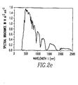
- FIGS 2a-e show, respectively, the curves for fluorescent light, a tungsten lamp, a flashlight, a photoflash and sunlight.
- These sources of background light generally have a greybody radiation signature. As can be seen, they generally have a peak occurring above 600 nm although sunlight has a broad spectrum which extends through and even below 500 nm.
- the other background sources illustrated have a significant irradiance at 520 nm although much less than at their peaks in the low 600 nm wavelengths. Thus, merely selecting a narrow band detector centered around 520 nm is not a satisfactory answer to discriminating arcing faults, as the background light sources also included this wavelength.
- an arcing fault is detected by gathering light from components susceptible to arcing faults and splitting this light into two beams.
- Light within a narrow band of wavelengths which includes a wavelength characteristic of arcing from the material of the component is extracted from the first beam by a first narrow beam sense filter.
- Light from a second narrow band of wavelengths, not including the characteristic wavelength for the arcing fault is extracted from the second beam by a second narrow band background filter.
- the second band of wavelengths is selected to have a wavelength range that has a greater intensity of the background light passed by the second or background filter than by the first or sense filter so that in the absence of an arcing fault, the light passed by the background filter will be greater than that passed by the sense filter.
- the output of the sense filter will exceed that of the background filter and can be used as the indication that an arcing fault is present.
- the sense filter was selected to be centered about 520 nm to detect the characteristic emission lines of copper and silver.
- the center wavelength of the background filter was selected to be 610 nm. While the selection of the center wavelength for the sensed filter is constrained by the characteristic emission lines of the arcing material, the center wavelength for the background filter has more flexibility. As mentioned, 610 nm was selected for the background filter because the intensity of this wavelength for most of these background sources was substantially more than at the 520 nm wavelength.
- the light passed by the sense filter and the light passed by the background filter are both converted to electrical signals by photodiodes.
- the resulting sensed light electrical signal and background light electrical signal are subtracted.
- the background light electrical signal will exceed the sensed light electrical signal.
- the sensed light electrical signal will be larger. Therefore these two electrical signals are subtracted and applied to a comparator which applies a threshold to the comparison so that an output indicating an arcing fault is only generated when the sensed light electrical signal exceeds the background light electrical signal by a set threshold amount.
- the wavelength bandwidth of the sense filter and the background filter should be substantially the same. Narrowing the bandwidth increases selectivity, but reduces sensitivity. For instance, a wavelength band of about 1.5 nm provides good selectivity but reduces the sensitivity since the level of the light is reduced. On the other hand, a bandwidth which is too wide, such as, for example, above about 25 nm, reduces the selectivity (provides a lower signal to noise ratio) and could result in false arcing fault indications, no tripping with an arcing fault or delayed tripping. Thus, the bandwidth of the two filters should be below about 25 nm and preferably should be about 5-10 nm.
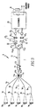
- FIG. 3 illustrates schematically an optical arc detector 1 in accordance with the invention.
- the detector 1 includes a light gathering section 3.
- the system shown as a plurality of input channels in the light gathering section 3 each provided by an optic fiber 5a-e.
- At a first or free end 7a-e of each of the optic fibers is light gathering optics 9a-e which increase the field of view of each channel.
- Second ends 11a-e of the optic fibers are coupled to a bifurcated fiber optic bundle 13 by a plexiglass ferrule 15.
- the bifurcated fiber bundle has a single input end 13 i and two output ends 13b and 13c. This bifurcated fiber bundle has a comb structure for the individual fibers in the bundle.
- the fibers of the bundle are smaller in diameter than the optic fibers 5 and are arranged so that light from each of the optic fibers 5a-e is transmitted to each of the output ends 13b and 13c of the fiber optic bundle thereby splitting the gathered light into a first beam 17 1 emanating from the first end 13 o1 and a second beam 17 2 emanating from the second end 13 o2 .
- the first beam 17 1 is passed through a first or sense interference filter 19 having a first narrow wavelength bandwidth centered on 520 nm to extract light characteristic of a copper or silver arc.
- the second beam 17 2 is passed through a second or background interference filter 21 having a narrow bandwidth centered at about 610 nm.
- this latter wavelength is chosen as a center wavelength because it is not a characteristic wavelength of the arcing material, in this case, copper or silver.
- This second beam 17 2 can also be passed through a neutral density filter 23.
- the light 17 1 ' extracted by the sense filter and the light 17 2 ' extracted by the background filter are focused by convex lenses 25 1 and 25 2 on photodiodes 27 1 and 27 2 which convert these light signals into the sensed light electrical signal and a background light electrical signal, respectively.
- These two electrical signals are processed by electronics 29 in the manner discussed above so that if an arcing fault is present and therefore the sensed light electrical signal exceeds the background light electrical signal by a set threshold amount, a circuit is completed to energize an output device such as a breaker trip solenoid 31.
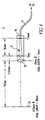
- Figure 4 illustrates an arrangement for the light gathering optics 9 which is used to increase the field of view (FOV) of the optic fibers 5.
- These light gathering optics 9 include a Fresnel lens 33 spaced in front of the convex lens 35 which focuses the light gathered by the Fresnel lens into an optical taper 37 in an enclosure 39.
- This optical taper 37 can be formed as a highly polished conical surface within the enclosure 39.
- the light gathering optics 9 permits each channel of the detector to monitor a larger section of the electric power system.
- the arrangement for generating the sensed light electrical signal and background light electrical signal are repeated schematically and the circuitry 29 for processing those electrical signals is shown in detail.
- the photodiodes 27 1 and 27 2 are connected in antiparallel so that their currents subtract.
- This difference between the sensed light current signal and the background light current signal is converted to a voltage signal by the differential amplifier 41.
- This differential voltage is then amplified, such as by a factor of ten, by the operational amplifier 43.
- the amplified voltage is compared to a reference voltage, which is set by a potentiometer 45 and a comparator 47.
- This potentiometer 45 sets a threshold by which the sensed light electrical signal must exceed the background light electrical signal in order for the comparator 47 to turn on a transistor 49.
- the transistor 49 provides the trigger signal to a one-shot multivibrator 51. Normally, the transistor 49 is off so that a pull-up resistor 53 applies +Vdc to the trigger input of the one-shot multivibrator 51.
- the transistor 49 is turned on pulling the trigger input of the one-shot multivibrator 51 down to ground. This causes the output of the multivibrator to go high turning on a second transistor 55 to energize an output relay 57 which is powered by the +Vdc supply.
- the output relay 57 is used to turn on the trip solenoid 31 which operates at 120 volts ac.
- the duration of the pulse generated by the one-shot multivibrator 51 is selected to assure actuation of the trip solenoid 31 long enough to trip the breaker and is set by timing capacitor 59 and resistor 61. Normally, the capacitor 59 is charged to +Vdc.
- the capacitor 59 is momentarily discharged through the "discharge" port of the one-shot. The capacitor 59 then begins to recharge with the time constant set by the resistor 61.
- the one-shot multivibrator 51 resets terminating the output pulse and thereby de-energizing the relay 57 and trip solenoid 31.
- Capacitor 63 is provided in the feedback path of the differential amplifier 41 for low pass filtering and frequency compensation. Back-to-back diodes 65 and 67 also in the feedback path compensate for the non-linear response of the photodiodes 27 1 and 27 2 .
- the five volt dc voltage +Vdc is generated by a battery 69 and regulator 71.
- a pair of photodiodes with the appropriate filter deposited directly to the diodes' glass cover could be used.
- Such integral photodiode/filter, type of photodiodes are available from the Coherent Corporation, Auburn Group.
- the functions performed by the electronic circuitry can be implemented in a micro controller.
- FIG. 6 illustrates an exemplary arrangement for the optics of the photodiodes 27 1 and 27 2 .
- Each of the narrow band filters 19 and 21 is separately mounted in an aluminum housing 72 in spaced relation to the convex lens 25 which focuses the filtered light onto the associated photodiode 27.
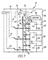
- FIG. 7 illustrates schematically an application of the optical art detector of the invention to distribution system switchgear.
- the switchgear 73 includes a metal switchgear cabinet 75.
- the cabinet 75 is divided into a forward compartment 77, a middle compartment 79 and a rear compartment 81.
- the forward compartment 77 is divided vertically into cells 83 in which are housed electrical switching apparatus such as circuit breakers 85.
- the middle compartment 79 houses rigid buses including a horizontal three-phase bus 87 which is connected to a set of vertical buses (only one visible) 89.
- the vertical buses are connected to the circuit breakers 85 through upper quick disconnects 91.
- Lower quick disconnects 93 connect the circuit breaker through runbacks 95 to cables 97 extending from the rear compartment 81.
- the optical arcing fault detector 1 of the invention can be used to protect the switchgear 73 from arcing faults which can occur between any of the conductors 87-97 or between such conductors and the metal cabinet 75.
- the optic fibers 5a-e can be inserted into the cells 83, the middle compartment 79 and the rear compartment 81 along with the appropriate light gathering optics like that shown in Figure 4 where they can gather light such as could occur from an arcing fault.
- the remainder of the optical arcing detector 99 can be contained in the top most cell 83 of the forward compartment 77 or any other convenient location.
- a trip signal can be sent to each of the circuit breakers 85 through a trip lead 101.
- a switchgear assembly typically includes several sections each having a forward, middle and rear compartment like that shown in Figure 7 mounted side-by-side.
- a common arcing fault detector can serve more than one switchgear section.
Landscapes
- Photometry And Measurement Of Optical Pulse Characteristics (AREA)
- Testing Of Short-Circuits, Discontinuities, Leakage, Or Incorrect Line Connections (AREA)
- Testing Electric Properties And Detecting Electric Faults (AREA)
- Gas-Insulated Switchgears (AREA)
Abstract
Description
Claims (20)
- Apparatus (1) for detecting an arcing fault at a component (87-97) of an electric power system where the arcing fault generates light at a predetermined wavelength in the presence of light from other sources which may include said predetermined wavelength, said apparatus comprising:light gathering means (3) aimed at said component to gather light as gathered light and splitting said gathered into a first light beam (171) and a second light beam (172);first filter means (19) extracting from said first beam (171) sensed light (17i') with a first wavelength bandwidth including said predetermined wavelength;second filter means (21) extracting from said second beam (172) background light (172') with a second wavelength bandwidth not including said predetermined wavelength; andresponse means (27,29,31) generating an arcing signal in response to a preselected relationship between said sensed light and said background light.
- The apparatus (1) of Claim 1 wherein said response means (27,29,31) comprises a first photodetector (271) generating a sensed light electrical signal from said sensed light, a second photodetector (272) generating a background light electrical signal from said background light and a comparator circuit (29) comparing said sensed light electrical signal and said background light electrical signal and generating said arcing signal when said sensed light electrical signal exceeds said background light electrical signal by at least a predetermined amount.
- The apparatus (1) of Claim 2 wherein said light gathering means (3) includes a bifurcated optic fiber bundle (13) having a first branch (13o1) generating said first beam (171) and a second branch (13o2) generating said second beam (172).
- The apparatus (1) of Claim 1 wherein said light gathering means (3) includes a bifurcated optic fiber bundle (13) having a first branch (13o1) generating said first beam (171) and a second branch (13o2) generating said second beam (172).
- The apparatus (1) of Claim 4 wherein said electric power system has a plurality of components (87-97) and wherein said light gathering means (3) comprises a plurality of optic fibers (5a-e) with first ends (7a-7e) aimed at said plurality of components and second ends (11a-11e) coupled to said bifurcated optic fiber bundle (13) which has a comb structure splitting the light gathered from all of said optic fibers into said first light beam (171) and said second light beam (172) which then each contain light from each optic fiber.
- The apparatus (1) of Claim 1 wherein said electric power system comprises switchgear (73) including a circuit breaker (83) and wherein said output means (27,29,31) comprises a trip circuit (29) tripping said circuit breaker in response to said arcing signal.
- The apparatus (1) of Claim 1 wherein said first wavelength bandwidth of said first filter means (19) includes 520 nm.
- The apparatus (1) of Claim 1 wherein said first wavelength bandwidth of said first filter means (19) is not more than about 25 nm wide.
- The apparatus (1) of Claim 8 wherein said first wavelength bandwidth of said first filter means (19) is about 5 to 10 nm wide.
- The apparatus (1) of Claim 9 wherein said second wavelength bandwidth of said second filter means (21) has a width about as wide as said first wavelength bandwidth of said first filter means (19).
- The apparatus (1) of Claim 1 wherein said second wavelength bandwidth of said second filter means (21) includes 610 nm.
- The apparatus (1) of Claim 7 wherein said second wavelength bandwidth of said second filter means (21) includes 620 nm.
- A method of detecting an arcing fault at a component (87-97) in an electric power system where said arcing fault generates light at a predetermined wavelength in the presence of light from other sources which may include said predetermined wavelength, said method comprising:gathering light from said component (87-97) as gathered light;extracting light (171') from said gathered light within a first band of wavelengths including said predetermined wavelength as sensed light;extracting light (172') within a second band of wavelengths not including said predetermined wavelength as background light;comparing said sensed light to said background light; andgenerating an output indicating a presence of an arcing fault based on results of said step of comparing.
- The method of Claim 13 wherein said step of gathering light includes splitting said gathered light into a first beam (171) and a second beam (172), wherein extracting light (171') within a first band of wavelengths comprises passing said first beam through a first filter (19) which passes light within said first band of wavelengths including said predetermined wavelength, and wherein extracting light (172') within said second band of wavelengths comprises passing said second beam (172) through a second filter (21) which passes light within said second band of wavelengths not including said predetermined wavelength.
- The method of Claim 14 wherein said step of comparing comprises converting said sensed light to a sensed light electrical signal, converting said background light to a background light electrical signal, subtracting said background light electrical signal from said sensed light electrical signal to generate a difference signal, and generating said arcing signal when said difference signal exceeds a preselected amount.
- The method of Claim 15 wherein said steps of extracting further include balancing of irradiance of light from said other sources in said first and second beams using a neutral density filter (23).
- The method of Claim 14 wherein said step of gathering includes gathering light from a plurality of components (87-97) in said electric power system and splitting said gathered light includes splitting light from each of said plurality of components into said first beam (171) and said second beam (172).
- The method of Claim 13 wherein said step of extracting light within said first band of wavelength includes light at about 520 nm.
- The method of Claim 18 wherein said first and second bands of wavelengths are not more than about 25 nm wide.
- The method of Claim 19 wherein said first and second bands of wavelengths are about 5-10 nm wide.
Applications Claiming Priority (2)
| Application Number | Priority Date | Filing Date | Title |
|---|---|---|---|
| US09/376,072 US6229680B1 (en) | 1999-08-16 | 1999-08-16 | Apparatus and method for optically detecting arcing faults in electric power systems in the presence of other light sources |
| US376072 | 1999-08-16 |
Publications (3)
| Publication Number | Publication Date |
|---|---|
| EP1077518A2 true EP1077518A2 (en) | 2001-02-21 |
| EP1077518A3 EP1077518A3 (en) | 2004-03-31 |
| EP1077518B1 EP1077518B1 (en) | 2006-06-21 |
Family
ID=23483595
Family Applications (1)
| Application Number | Title | Priority Date | Filing Date |
|---|---|---|---|
| EP00116258A Expired - Lifetime EP1077518B1 (en) | 1999-08-16 | 2000-08-08 | Apparatus and method for optically detecting arcing faults in electric power systems in the presence of other light sources |
Country Status (6)
| Country | Link |
|---|---|
| US (1) | US6229680B1 (en) |
| EP (1) | EP1077518B1 (en) |
| AU (1) | AU772876B2 (en) |
| BR (1) | BR0003731A (en) |
| CA (1) | CA2315513A1 (en) |
| DE (1) | DE60028883T2 (en) |
Cited By (5)
| Publication number | Priority date | Publication date | Assignee | Title |
|---|---|---|---|---|
| EP1806817A1 (en) | 2006-01-09 | 2007-07-11 | Luis Gonzalo Flores Losada | Oil-immersed electrical equipment with a short-circuiting safety device |
| EP1971007A1 (en) * | 2007-03-16 | 2008-09-17 | ABB Technology AG | System and method for fault protection in compact secondary substations |
| EP2522995A3 (en) * | 2011-05-13 | 2018-01-10 | General Electric Company | Methods, systems, and apparatus for detecting light and acoustic waves |
| EP3439128A1 (en) * | 2017-08-03 | 2019-02-06 | Schneider Electric Industries SAS | Method and device for protection against internal arcing faults in an electrical distribution system, and electrical cabinet comprising such a device |
| WO2020030518A1 (en) * | 2018-08-07 | 2020-02-13 | Siemens Aktiengesellschaft | Device for detecting an arc fault, and electrical switchgear |
Families Citing this family (52)
| Publication number | Priority date | Publication date | Assignee | Title |
|---|---|---|---|---|
| US6532424B1 (en) | 1995-03-13 | 2003-03-11 | Square D Company | Electrical fault detection circuit with dual-mode power supply |
| US6377427B1 (en) | 1995-03-13 | 2002-04-23 | Square D Company | Arc fault protected electrical receptacle |
| US6242993B1 (en) | 1995-03-13 | 2001-06-05 | Square D Company | Apparatus for use in arcing fault detection systems |
| US6625550B1 (en) | 1998-02-19 | 2003-09-23 | Square D Company | Arc fault detection for aircraft |
| US6477021B1 (en) | 1998-02-19 | 2002-11-05 | Square D Company | Blocking/inhibiting operation in an arc fault detection system |
| US6567250B1 (en) | 1998-02-19 | 2003-05-20 | Square D Company | Arc fault protected device |
| US6414829B1 (en) | 1998-02-19 | 2002-07-02 | Square D Company | Arc fault circuit interrupter |
| US6782329B2 (en) | 1998-02-19 | 2004-08-24 | Square D Company | Detection of arcing faults using bifurcated wiring system |
| US6456471B1 (en) | 1998-02-19 | 2002-09-24 | Square D Company | Test, reset and communications operations in an ARC fault circuit interrupter with optional memory and/or backup power |
| US6621669B1 (en) | 1998-02-19 | 2003-09-16 | Square D Company | Arc fault receptacle with a feed-through connection |
| US6433976B1 (en) * | 1999-09-24 | 2002-08-13 | Square D Company | Instantaneous arc fault light detector with resistance to false tripping |
| US6693438B2 (en) | 2002-02-12 | 2004-02-17 | Eaton Corporation | Self-powered apparatus and method for optically detecting arcing faults in electric power systems in the presence of other light sources |
| US20030231439A1 (en) * | 2002-06-14 | 2003-12-18 | Juds Mark Allan | Bullet assembly for a vacuum arc interrupter |
| US6813127B2 (en) * | 2002-06-14 | 2004-11-02 | Eaton Corporation | Blade tip for puncturing cupro-nickel seal cup |
| US6724604B2 (en) | 2002-06-14 | 2004-04-20 | Eaton Corporation | Shorting switch and system to eliminate arcing faults in power distribution equipment |
| US6839209B2 (en) * | 2002-06-14 | 2005-01-04 | Eaton Corporation | Shorting switch and system to eliminate arcing faults in power distribution equipment |
| US6952332B2 (en) * | 2002-06-14 | 2005-10-04 | Eaton Corporation | Vacuum arc eliminator having a bullet assembly actuated by a gas generating device |
| US6633009B1 (en) | 2002-06-14 | 2003-10-14 | Eaton Corporation | Shorting switch and system to eliminate arcing faults in low voltage power distribution equipment |
| US6853525B2 (en) * | 2002-06-14 | 2005-02-08 | Eaton Corporation | Vacuum arc interrupter actuated by a gas generated driving force |
| US6657150B1 (en) | 2002-06-14 | 2003-12-02 | Eaton Corporation | Shorting switch and system to eliminate arcing faults in power distribution equipment |
| US6853524B2 (en) * | 2002-06-14 | 2005-02-08 | Eaton Corporation | Vacuum arc interrupter having a tapered conducting bullet assembly |
| US7035068B2 (en) * | 2003-12-05 | 2006-04-25 | Eaton Corporation | Apparatus and method employing an optical fiber for closed-loop feedback detection of arcing faults |
| CN100385212C (en) * | 2003-12-24 | 2008-04-30 | 孙艺夫 | Optical signal collecting and on-line monitoring method for electric power equipment internal failure |
| US7145757B2 (en) * | 2004-01-13 | 2006-12-05 | Eaton Corporation | System for eliminating arcing faults and power distribution system employing the same |
| US7536914B2 (en) * | 2005-07-18 | 2009-05-26 | The Johns Hopkins University | Sensor for detecting arcing faults |
| US7787113B2 (en) * | 2006-05-19 | 2010-08-31 | Siemens Industry, Inc. | Method for optically detecting an electrical arc in a power supply |
| MX2011002464A (en) | 2008-09-19 | 2011-04-05 | Schweitzer Engineering Lab Inc | Protective device with metering and oscillography. |
| US8803069B2 (en) * | 2008-09-19 | 2014-08-12 | Schweitzer Engineering Laboratories, Inc. | Electro-optical radiation collector for arc flash detection |
| BRPI0918900A2 (en) * | 2008-09-19 | 2017-08-01 | Schweitzer Engineering Lab Inc | apparatus for validating an electrical arc detection unit (afdu), computer readable storage medium, and method for determining the configuration of an electrical arc detection unit (afdu) |
| EP2327129A4 (en) * | 2008-09-19 | 2013-09-04 | Schweitzer Engineering Lab Inc | Secure arc flash detection |
| AU2009293077B2 (en) * | 2008-09-19 | 2012-07-19 | Schweitzer Engineering Laboratories, Inc. | Arc flash protection with self-test |
| EP2230736B1 (en) | 2009-03-20 | 2014-12-17 | ABB Research Ltd. | Encapsulation system for a single phase encapsulated channel switchgear |
| US8054594B2 (en) * | 2009-06-18 | 2011-11-08 | General Electric Company | ARC flash detection system |
| US8040517B1 (en) * | 2010-04-30 | 2011-10-18 | General Electric Company | Arc flash detection system and method |
| US8228652B2 (en) | 2010-06-02 | 2012-07-24 | Eaton Corporation | Arc flash detection apparatus and electrical system including the same |
| US8564915B2 (en) * | 2010-09-08 | 2013-10-22 | General Electric Company | Methods, systems, and apparatus for detecting arc flash events using light and time discrimination |
| US8576521B2 (en) | 2011-08-16 | 2013-11-05 | Schneider Electric USA, Inc. | Adaptive light detection for arc mitigation systems |
| US9053881B2 (en) | 2012-08-24 | 2015-06-09 | Schneider Electric USA, Inc. | Arc detection with resistance to nuisance activation through light subtraction |
| CN102840917A (en) * | 2012-08-29 | 2012-12-26 | 山东电力集团公司淄博供电公司 | Transmission and distribution electromagnetic spectrum joint detector |
| US9438028B2 (en) | 2012-08-31 | 2016-09-06 | Schweitzer Engineering Laboratories, Inc. | Motor relay with integrated arc-flash detection |
| EP2806449B8 (en) * | 2013-05-22 | 2017-05-31 | ABB Schweiz AG | A coil actuator a for low and medium voltage switching apparatus and an arc fault coil suppression device comprising said coil actuator |
| US10439733B2 (en) | 2014-01-13 | 2019-10-08 | The Johns Hopkins University | Fiber optic circuit breaker |
| DE102014112723A1 (en) * | 2014-09-04 | 2016-03-10 | Eaton Industries Austria Gmbh | A method of distinguishing an arc from a luminous gas containing at least metal vapor |
| DE102015220162A1 (en) * | 2015-10-16 | 2017-04-20 | Robert Bosch Gmbh | Control unit for a vehicle with an arc sensor |
| US10804689B2 (en) | 2016-11-18 | 2020-10-13 | Schweitzer Engineering Laboratories, Inc. | Methods and systems for evaluating arc flash exposure hazard |
| CN106786408B (en) * | 2016-12-25 | 2018-11-06 | 湖北知本信息科技有限公司 | A kind of electric arc light protection method |
| CN108110736B (en) * | 2016-12-25 | 2019-07-26 | 湖北知本信息科技有限公司 | A kind of arc light protective device |
| WO2018217883A2 (en) | 2017-05-23 | 2018-11-29 | Pass & Seymour, Inc. | Arc fault circuit interrupter |
| US10535988B2 (en) | 2017-08-03 | 2020-01-14 | Eaton Intelligent Power Limited | Arc flash detection apparatus and electrical system including the same |
| US10928435B2 (en) | 2019-07-15 | 2021-02-23 | The Boeing Company | Electrical fault detector and method of use |
| US11837862B2 (en) | 2020-10-09 | 2023-12-05 | Schweitzer Engineering Laboratories, Inc. | Arc-flash sensor using optical fiber |
| EP4113136A1 (en) | 2021-06-29 | 2023-01-04 | Abb Schweiz Ag | Testing an arc detecting system |
Family Cites Families (15)
| Publication number | Priority date | Publication date | Assignee | Title |
|---|---|---|---|---|
| US3999074A (en) * | 1973-08-02 | 1976-12-21 | Callaghan James M | Fiber-optic photoelectric power control device |
| DE2856188C2 (en) | 1978-12-27 | 1985-09-05 | Brown, Boveri & Cie Ag, 6800 Mannheim | Device for the detection of arcing faults in switchgear |
| DE3129041A1 (en) * | 1981-07-23 | 1983-02-03 | BBC Aktiengesellschaft Brown, Boveri & Cie., 5401 Baden, Aargau | FIBER OPTICAL SENSOR FOR DETECTING ELECTRIC ARCH DISCHARGE |
| US4461571A (en) | 1982-05-05 | 1984-07-24 | Westinghouse Electric Corp. | Test system for wave guide arc detector circuits |
| DE3331221A1 (en) * | 1983-08-30 | 1985-03-07 | Siemens AG, 1000 Berlin und 8000 München | SWITCHING DEVICE FOR DETECTING TROUBLE ARC IN ELECTRICAL SYSTEMS |
| JPS626181A (en) | 1985-07-02 | 1987-01-13 | Mitsubishi Electric Corp | Abnormality detection device for gas insulating apparatus |
| US4791518A (en) | 1986-06-09 | 1988-12-13 | Bbc Brown Boveri Ag | Device for detecting interfering arcs |
| FR2621748B1 (en) | 1987-10-09 | 1996-07-05 | Merlin Gerin | STATIC TRIGGER OF A MOLDED CASE CIRCUIT BREAKER |
| FR2642913B1 (en) | 1989-02-07 | 1991-04-12 | Alsthom Gec | SAFETY DEVICE FOR ELECTRICAL APPARATUS WITH DIELECTRIC GAS, IN PARTICULAR FOR MEASUREMENT CIRCUIT BREAKERS OR REDUCERS |
| FR2668294B1 (en) | 1990-10-22 | 1993-09-24 | Alsthom Gec | ARC DETECTION CIRCUIT BREAKER. |
| US5185686A (en) * | 1991-03-28 | 1993-02-09 | Eaton Corporation | Direction sensing arc detection |
| US5361313A (en) * | 1993-05-11 | 1994-11-01 | Martin Marietta Corporation | Two-mode remote fiber optic sensor |
| DE4345170A1 (en) | 1993-09-21 | 1995-03-23 | Kloeckner Moeller Gmbh | Arc fault protection device for switchgear for the distribution of electrical energy |
| US5513002A (en) * | 1994-03-17 | 1996-04-30 | The A.R.T. Group, Inc. | Optical corona monitoring system |
| DE29502452U1 (en) * | 1995-02-15 | 1996-06-13 | Klöckner-Moeller GmbH, 53115 Bonn | Arrangement for room-selective detection of arcing faults in switchgear |
-
1999
- 1999-08-16 US US09/376,072 patent/US6229680B1/en not_active Expired - Lifetime
-
2000
- 2000-08-08 EP EP00116258A patent/EP1077518B1/en not_active Expired - Lifetime
- 2000-08-08 DE DE60028883T patent/DE60028883T2/en not_active Expired - Fee Related
- 2000-08-11 CA CA002315513A patent/CA2315513A1/en not_active Abandoned
- 2000-08-14 AU AU53374/00A patent/AU772876B2/en not_active Ceased
- 2000-08-16 BR BR0003731-1A patent/BR0003731A/en not_active IP Right Cessation
Cited By (9)
| Publication number | Priority date | Publication date | Assignee | Title |
|---|---|---|---|---|
| EP1806817A1 (en) | 2006-01-09 | 2007-07-11 | Luis Gonzalo Flores Losada | Oil-immersed electrical equipment with a short-circuiting safety device |
| US7755868B2 (en) | 2006-01-09 | 2010-07-13 | Luis Gonzalo Flores Losada | Electrical equipment for distribution network |
| EP1971007A1 (en) * | 2007-03-16 | 2008-09-17 | ABB Technology AG | System and method for fault protection in compact secondary substations |
| US8369058B2 (en) | 2007-03-16 | 2013-02-05 | Abb Technology Ltd. | Compact secondary substation comprising a fault protection system, a method for fault protection in a compact secondary substation, and a control unit for performing the method |
| EP2522995A3 (en) * | 2011-05-13 | 2018-01-10 | General Electric Company | Methods, systems, and apparatus for detecting light and acoustic waves |
| EP3439128A1 (en) * | 2017-08-03 | 2019-02-06 | Schneider Electric Industries SAS | Method and device for protection against internal arcing faults in an electrical distribution system, and electrical cabinet comprising such a device |
| FR3069951A1 (en) * | 2017-08-03 | 2019-02-08 | Schneider Electric Industries Sas | METHOD AND DEVICE FOR PROTECTION AGAINST INTERNAL ARC DEFECTS IN AN ELECTRICAL DISTRIBUTION SYSTEM, AND ELECTRICAL CABINET HAVING SUCH A DEVICE |
| US10958061B2 (en) | 2017-08-03 | 2021-03-23 | Schneider Electric Industries Sas | Method and device for protection from internal arcs in an electrical distribution system, and electrical cabinet including such a device |
| WO2020030518A1 (en) * | 2018-08-07 | 2020-02-13 | Siemens Aktiengesellschaft | Device for detecting an arc fault, and electrical switchgear |
Also Published As
| Publication number | Publication date |
|---|---|
| BR0003731A (en) | 2001-03-27 |
| AU5337400A (en) | 2001-02-22 |
| DE60028883D1 (en) | 2006-08-03 |
| AU772876B2 (en) | 2004-05-13 |
| DE60028883T2 (en) | 2007-01-25 |
| EP1077518B1 (en) | 2006-06-21 |
| US6229680B1 (en) | 2001-05-08 |
| CA2315513A1 (en) | 2001-02-16 |
| EP1077518A3 (en) | 2004-03-31 |
Similar Documents
| Publication | Publication Date | Title |
|---|---|---|
| US6229680B1 (en) | Apparatus and method for optically detecting arcing faults in electric power systems in the presence of other light sources | |
| US6693438B2 (en) | Self-powered apparatus and method for optically detecting arcing faults in electric power systems in the presence of other light sources | |
| US7035068B2 (en) | Apparatus and method employing an optical fiber for closed-loop feedback detection of arcing faults | |
| US7580232B2 (en) | Arc detection system and method | |
| JP5571782B2 (en) | Arc flash detection system | |
| US6839209B2 (en) | Shorting switch and system to eliminate arcing faults in power distribution equipment | |
| US10958061B2 (en) | Method and device for protection from internal arcs in an electrical distribution system, and electrical cabinet including such a device | |
| JPS6346933B2 (en) | ||
| AU680549B2 (en) | Switching installation for distributing electric power protected against arc interference | |
| DK504289A (en) | BUERELAE | |
| US20070268482A1 (en) | Method for optically detecting an electrical arc in a power supply | |
| SE452664B (en) | DEVICE FOR MONITORING OF ELECTRICAL DEVICES WITH REGARD TO THE RISE OF ONE OR MORE LIGHT BAGS | |
| MX2008014698A (en) | System for optically detecting an electrical arc in a power supply. | |
| MXPA00007949A (en) | Apparatus and method for optically detecting arcing faults in electric power systems in the presence of other light sources | |
| CN102684152A (en) | Special fault electric arc detection arc-extinguishing device for photovoltaic confluence | |
| EP0274326B1 (en) | Arc detection at a set of bars of an electric panel or of a switching cabinet | |
| KR102476521B1 (en) | Differentiating-integrating type arc sensor capable of detecting both duration and peak duration of arc generated within swithgear | |
| US8829412B1 (en) | Remote monitoring of glow tube light output including a logic unit maintaining an indication of a monitored glow tube discharge while no discharge is detected | |
| KR102494281B1 (en) | Differentiating-integrating type arc and fire sensor capable of detecting simultaneolsly duration and peak duration of arc and flame generated within swithboard and having 360 degrees sensing range and control device thereof | |
| JPH04265619A (en) | Flashover indicator | |
| JPH065888A (en) | Photodetector and failure monitoring device for electric equipment using the same | |
| JP2021096095A (en) | Arc beam detector | |
| JPH0572250A (en) | Detection of fault iron tower | |
| EP1083644A1 (en) | Earth fault protection device sensitive to arc currents, trip device and circuit breaker comprising such a device | |
| JPH04255420A (en) | Protective system for distribution line |
Legal Events
| Date | Code | Title | Description |
|---|---|---|---|
| PUAI | Public reference made under article 153(3) epc to a published international application that has entered the european phase |
Free format text: ORIGINAL CODE: 0009012 |
|
| AK | Designated contracting states |
Kind code of ref document: A2 Designated state(s): AT BE CH CY DE DK ES FI FR GB GR IE IT LI LU MC NL PT SE |
|
| AX | Request for extension of the european patent |
Free format text: AL;LT;LV;MK;RO;SI |
|
| RIN1 | Information on inventor provided before grant (corrected) |
Inventor name: SHEA, JOHN JOSEPH |
|
| PUAL | Search report despatched |
Free format text: ORIGINAL CODE: 0009013 |
|
| AK | Designated contracting states |
Kind code of ref document: A3 Designated state(s): AT BE CH CY DE DK ES FI FR GB GR IE IT LI LU MC NL PT SE |
|
| AX | Request for extension of the european patent |
Extension state: AL LT LV MK RO SI |
|
| 17P | Request for examination filed |
Effective date: 20040924 |
|
| AKX | Designation fees paid |
Designated state(s): DE FR GB IT |
|
| 17Q | First examination report despatched |
Effective date: 20050308 |
|
| GRAP | Despatch of communication of intention to grant a patent |
Free format text: ORIGINAL CODE: EPIDOSNIGR1 |
|
| GRAS | Grant fee paid |
Free format text: ORIGINAL CODE: EPIDOSNIGR3 |
|
| GRAA | (expected) grant |
Free format text: ORIGINAL CODE: 0009210 |
|
| AK | Designated contracting states |
Kind code of ref document: B1 Designated state(s): DE FR GB IT |
|
| REG | Reference to a national code |
Ref country code: GB Ref legal event code: FG4D |
|
| REF | Corresponds to: |
Ref document number: 60028883 Country of ref document: DE Date of ref document: 20060803 Kind code of ref document: P |
|
| ET | Fr: translation filed | ||
| PLBE | No opposition filed within time limit |
Free format text: ORIGINAL CODE: 0009261 |
|
| STAA | Information on the status of an ep patent application or granted ep patent |
Free format text: STATUS: NO OPPOSITION FILED WITHIN TIME LIMIT |
|
| 26N | No opposition filed |
Effective date: 20070322 |
|
| PGFP | Annual fee paid to national office [announced via postgrant information from national office to epo] |
Ref country code: DE Payment date: 20070831 Year of fee payment: 8 |
|
| PGFP | Annual fee paid to national office [announced via postgrant information from national office to epo] |
Ref country code: GB Payment date: 20070705 Year of fee payment: 8 |
|
| PGFP | Annual fee paid to national office [announced via postgrant information from national office to epo] |
Ref country code: FR Payment date: 20070803 Year of fee payment: 8 |
|
| PGFP | Annual fee paid to national office [announced via postgrant information from national office to epo] |
Ref country code: IT Payment date: 20080816 Year of fee payment: 9 |
|
| GBPC | Gb: european patent ceased through non-payment of renewal fee |
Effective date: 20080808 |
|
| REG | Reference to a national code |
Ref country code: FR Ref legal event code: ST Effective date: 20090430 |
|
| PG25 | Lapsed in a contracting state [announced via postgrant information from national office to epo] |
Ref country code: DE Free format text: LAPSE BECAUSE OF NON-PAYMENT OF DUE FEES Effective date: 20090303 Ref country code: FR Free format text: LAPSE BECAUSE OF NON-PAYMENT OF DUE FEES Effective date: 20080901 |
|
| PG25 | Lapsed in a contracting state [announced via postgrant information from national office to epo] |
Ref country code: GB Free format text: LAPSE BECAUSE OF NON-PAYMENT OF DUE FEES Effective date: 20080808 |
|
| PG25 | Lapsed in a contracting state [announced via postgrant information from national office to epo] |
Ref country code: IT Free format text: LAPSE BECAUSE OF NON-PAYMENT OF DUE FEES Effective date: 20090808 |