EP1077089A2 - Method for driving liquid drop spraying apparatus - Google Patents
Method for driving liquid drop spraying apparatus Download PDFInfo
- Publication number
- EP1077089A2 EP1077089A2 EP00306982A EP00306982A EP1077089A2 EP 1077089 A2 EP1077089 A2 EP 1077089A2 EP 00306982 A EP00306982 A EP 00306982A EP 00306982 A EP00306982 A EP 00306982A EP 1077089 A2 EP1077089 A2 EP 1077089A2
- Authority
- EP
- European Patent Office
- Prior art keywords
- pressure
- pressure chamber
- time
- pressurization
- pressure chambers
- Prior art date
- Legal status (The legal status is an assumption and is not a legal conclusion. Google has not performed a legal analysis and makes no representation as to the accuracy of the status listed.)
- Withdrawn
Links
Images


Classifications
-
- F—MECHANICAL ENGINEERING; LIGHTING; HEATING; WEAPONS; BLASTING
- F02—COMBUSTION ENGINES; HOT-GAS OR COMBUSTION-PRODUCT ENGINE PLANTS
- F02M—SUPPLYING COMBUSTION ENGINES IN GENERAL WITH COMBUSTIBLE MIXTURES OR CONSTITUENTS THEREOF
- F02M61/00—Fuel-injectors not provided for in groups F02M39/00 - F02M57/00 or F02M67/00
- F02M61/02—Fuel-injectors not provided for in groups F02M39/00 - F02M57/00 or F02M67/00 of valveless type
-
- B—PERFORMING OPERATIONS; TRANSPORTING
- B05—SPRAYING OR ATOMISING IN GENERAL; APPLYING FLUENT MATERIALS TO SURFACES, IN GENERAL
- B05B—SPRAYING APPARATUS; ATOMISING APPARATUS; NOZZLES
- B05B12/00—Arrangements for controlling delivery; Arrangements for controlling the spray area
- B05B12/08—Arrangements for controlling delivery; Arrangements for controlling the spray area responsive to condition of liquid or other fluent material to be discharged, of ambient medium or of target ; responsive to condition of spray devices or of supply means, e.g. pipes, pumps or their drive means
- B05B12/085—Arrangements for controlling delivery; Arrangements for controlling the spray area responsive to condition of liquid or other fluent material to be discharged, of ambient medium or of target ; responsive to condition of spray devices or of supply means, e.g. pipes, pumps or their drive means responsive to flow or pressure of liquid or other fluent material to be discharged
-
- B—PERFORMING OPERATIONS; TRANSPORTING
- B05—SPRAYING OR ATOMISING IN GENERAL; APPLYING FLUENT MATERIALS TO SURFACES, IN GENERAL
- B05B—SPRAYING APPARATUS; ATOMISING APPARATUS; NOZZLES
- B05B17/00—Apparatus for spraying or atomising liquids or other fluent materials, not covered by the preceding groups
- B05B17/04—Apparatus for spraying or atomising liquids or other fluent materials, not covered by the preceding groups operating with special methods
- B05B17/06—Apparatus for spraying or atomising liquids or other fluent materials, not covered by the preceding groups operating with special methods using ultrasonic or other kinds of vibrations
- B05B17/0607—Apparatus for spraying or atomising liquids or other fluent materials, not covered by the preceding groups operating with special methods using ultrasonic or other kinds of vibrations generated by electrical means, e.g. piezoelectric transducers
-
- F—MECHANICAL ENGINEERING; LIGHTING; HEATING; WEAPONS; BLASTING
- F02—COMBUSTION ENGINES; HOT-GAS OR COMBUSTION-PRODUCT ENGINE PLANTS
- F02M—SUPPLYING COMBUSTION ENGINES IN GENERAL WITH COMBUSTIBLE MIXTURES OR CONSTITUENTS THEREOF
- F02M51/00—Fuel-injection apparatus characterised by being operated electrically
- F02M51/06—Injectors peculiar thereto with means directly operating the valve needle
- F02M51/0603—Injectors peculiar thereto with means directly operating the valve needle using piezoelectric or magnetostrictive operating means
Definitions
- the present invention relates to a method for driving liquid drop spraying or ejecting apparatus, which is used for example in a raw material or fuel discharging device used in a variety of applications, the discharging device treating a liquid or operating by discharging a liquid raw material or fuel.
- a plurality of pressure chambers were connected to an identical flow path via an introducing hole provided in each of the pressure chambers, and liquid drops were discharged from a discharge opening with a volume change of the pressure chamber, thereby performing spraying.
- the liquid supplied to a plurality of pressure chambers with respect to one flow path was accumulated through the introducing hole formed in each pressure chamber, liquid drops were discharged from a nozzle hole connected to the other of the respective pressure chambers with a volume change of the pressure chamber, and the entirety enters the sprayed state.
- a liquid drops spraying apparatus in which piezoelectric / electrostrictive elements are formed at part of the wall of the pressure chamber, and a pressure change is generated at the element with a voltage signal applied to the element was superior in liquid drops sprayed state.
- a plurality of pressure chambers of the liquid drops spraying apparatus were increased or the discharge cycle was decreased.
- a method for driving the apparatus is characterized in that the pressure chambers are divided into at least two or more groups, and drive timings for causing the volume change between these groups are set so as to be different from each other.
- a drive timing denotes a time when the volume of the pressure chamber starts its change.
- the pressure chambers each produce a volume change by each group, and the quantity of liquid that flows from the introducing hole back to the flow path and fluctuation in the liquid pressure can be reduced.
- the pressure chambers may be divided into two classes according to a time when pressurization starts, and can be divided into three or more classes by shifting them sequentially and providing a time difference.
- a method for dividing a liquid drops spraying apparatus in which piezoelectric / electrostrictive elements are provided at a part of the wall of the pressure chamber so that a time of command for applying a voltage signal to the piezoelectric / electrostrictive elements by each of the groups is different from another.
- the voltage signal applied to the piezoelectric / electrostrictive elements is controlled at a short period, whereby the spraying quantity can be increased.
- a method for driving a liquid drops spraying apparatus in which two pressure chambers having the adjacent discharge openings are divided into another group.
- the adjacent pressure chambers are most likely to be affected by the flow from each introducing hole back to the flow path.
- an advantageous effect of differentiating the drive timing is significantly attained.
- the back flow from one of the adjacent pressure chambers is utilized, whereby the liquid can be supplied smoothly to the other pressure chamber.
- the wires for applying voltage signals to the piezoelectric / electrostrictive elements of the pressure chamber may be provided alternately.
- individual wiring is provided to a control unit, whereby a timing of applying a voltage signal from the control unit can be controlled. In particular, in the latter case, the timing of applying the signal can be set via wiring or flexibly.
- a method for driving liquid drops spraying apparatus is characterized in that, in a duration from a time when pressure reducing of one pressure chamber starts to a time when the next pressurization starts, the pressurization of the other pressure chamber is started. In this manner, the flow from the introducing hole back to the flow path can be prevented, and the back flow generated in one of the adjacent pressure chambers is utilized, whereby the liquid can be supplied smoothly to the other chamber.
- a method for driving a liquid drops spraying apparatus in which, when pressure reducing of one pressure chamber starts in a duration from a time when pressure reducing of said one pressure chamber to a time when the next pressurization of that pressure chamber starts, the pressurization of the other pressure chamber is started.
- Fig. 1 is an illustrative view illustrating a face on which a discharge opening 11 of a liquid drops spraying apparatus 1 is arranged.
- pressure chambers 10a, 10b,... 10n-1, 10n having an outwardly opening discharge opening 11 provided therein are arranged in order.
- An introducing hole 12 is provided to be inserted into the other end of a face opposite to the face on which the discharge opening 11 of each pressure chamber 10n is provided, and a number of pieces of pressure chambers are connected to the identical flow path 20 via the introducing hole 12.
- the flow path 20 can be provided to a liquid supply source in one or more multiple arrays.
- the piezoelectric / electrostrictive elements 13 are provided at part of its wall, and each of the piezoelectric / electrostrictive elements 13 laminates upper electrode (not shown) and each piezoelectric / electrostrictive layer and a lower electrode (not shown). At least one of the upper and lower electrodes laminated on each of the piezoelectric / electrostrictive elements 13 is coupled via wires 13a and 13b adjacently connected to the control unit alternately.
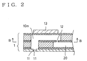
- Fig. 2 is a cross section taken in line A-A of Fig. 1.
- the introducing hole 12 connected to each pressure chamber 10n is provided at the flow path 20 common to a plurality of pressure chambers 10n.
- the piezoelectric / electrostrictive elements 13 are provided at part of the upper wall of the pressure chamber 10n.
- a discharge opening 11 for outwardly discharging a liquid is punched at the tip end of the lower face, and a nozzle hole lla is formed at its tip end.
- Fig. 1 is a view showing a direction indicated by the arrow B.
- a predetermined voltage signal is applied to the upper and lower electrodes laminated on the piezoelectric / electrostrictive elements 13, whereby a piezoelectric / electric strain layer is deformed with a change in electric field generated between the upper and lower electrodes.
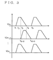
- Fig. 3 is an illustrative view illustrating a timing of applying voltage signals to the piezoelectric / electrostrictive elements 13.
- a signal is applied in the case where a wall face having the piezoelectric / electrostrictive elements fixed thereto is deformed in a direction in which the volume reduction (pressurization) of the pressure chamber takes place when a voltage is applied, i.e., when an electric field is applied.
- the volume reduction (pressurization) of the pressure chamber may be generated, when a voltage is released. In this case, the direction of voltage application or release is reversed.
- two pressure chambers 10n and 10n-1 each having the adjacent nozzle holes lla hold a state when pressurization is started from time T1, and is ended at time T2, and holds on its state until time T3 has come.
- Pressure reducing is started from time T3, pressure reducing is ended until time T4 has come, and a time ready for the next pressurization has come.
- This cycle is repeated.
- time T1 (-1) for starting pressurization of the other pressure chamber 10n-1 is set. In this manner, the flow from one introducing hole back to the flow path can be reduced when such flow is subjected to the other introducing hole.
- a signal application timing is differentiated from another between the adjacent pressure chambers
- the timing may be differentiated between pressure chambers which are not adjacent to each other.
- groups for differentiating the timing may be divided into three or more sections. In that case, at the pressurization start time of each group, as shown in Fig. 4, times T1 (1) and T1 (2) for starting the next pressurization may be provided in a driving cycle with equal intervals.
- a method for driving a liquid drops spraying apparatus in which the pressure chambers of the liquid drops spraying apparatus are divided into at least two or more groups, and drive timings for generating the volume change between these groups are set so as to be different from each other.
- all of the pressure chambers do not cause a volume change simultaneously, and a change in liquid quantity and liquid pressure during liquid flowing from the introducing hole back to the flow path can be reduced.
- piezoelectric / electrostrictive elements are provided at part of the wall of the pressure chamber so that a time of command for applying a voltage signal to the piezoelectric / electrostrictive element by each of the groups is differentiated from another.
- the voltage signals to be applied to the piezoelectric / electrostrictive elements are controlled within a short cycle, whereby the discharge count per unit time can be increased, and the spraying quantity can be increased.
- the groups of the pressure chambers having the adjacent discharge openings are divided into two groups.
- the back flow from one of the adjacent pressure chambers is utilized, whereby the liquid can be supplied smoothly to the other pressure chamber.
- a liquid drops spraying apparatus for discharging liquid drops from the discharge opening by means of a volume change of these pressure chambers by pressure reduced after the pressure chamber has been pressurized, thereby performed spraying, in which in a duration from a time when pressure reducing of one pressure chamber starts to a time when the next pressurization of the pressure chamber starts, the pressurization of the other pressure chamber is started.
- the invention also provides liquid drop spraying or ejecting apparatus having control means arranged to carry out the methods herein described.
Landscapes
- Engineering & Computer Science (AREA)
- Chemical & Material Sciences (AREA)
- Combustion & Propulsion (AREA)
- Mechanical Engineering (AREA)
- General Engineering & Computer Science (AREA)
- Application Of Or Painting With Fluid Materials (AREA)
- Special Spraying Apparatus (AREA)
- Fuel-Injection Apparatus (AREA)
- Spray-Type Burners (AREA)
- Spray Control Apparatus (AREA)
- Nozzles (AREA)
Abstract
Description
Claims (5)
- A method of driving a liquid drop spraying apparatus in which a plurality of pressure chambers are connected to one flow path via an introducing hole provided in each of the pressure chambers, and liquid drops are discharged from a discharge opening by means of a volume change of the pressure chamber, thereby performing spraying, comprising the steps of: dividing the pressure chambers into at least two or more groups, and setting drive timings for causing the volume change between these groups so as to be different from each other.
- A method as claimed in claim 1, wherein a piezoelectric /electrostrictive element is provided at part of the wall of said pressure chamber so that the timings of commands for applying a voltage signal to the piezoelectric/electrostrictive elements of said each group are different from each other.
- A method as claimed in claim 1, wherein the groups of said pressure chambers are divided into two sections in which the discharge openings in one section are contiguous to the discharge openings in another section.
- A method of driving a liquid drop spraying apparatus in which a plurality of pressure chambers are connected to one flow path via an introducing hole provided in each of the pressure chambers, and liquid drops are discharged from a discharge opening by means of a volume change of the pressure chamber by pressure reduction after the pressure chambers have been pressurized, thereby performing spraying, comprising the step of, in a duration from a time when pressure reduction of one pressure chamber starts to a time when the next pressurization of that pressure chamber starts, starting the pressurization of another pressure chamber.
- A method as claimed in claim 4, wherein, when pressure reducing of one pressure chamber starts in a duration from a time when pressure reducing of said one pressure chamber to a time when the next pressurization of that pressure chamber starts, the pressurization of the other pressure chamber is started.
Applications Claiming Priority (2)
| Application Number | Priority Date | Filing Date | Title |
|---|---|---|---|
| JP23326399 | 1999-08-19 | ||
| JP11233263A JP2001054749A (en) | 1999-08-19 | 1999-08-19 | Droplet sprayer driving method |
Publications (2)
| Publication Number | Publication Date |
|---|---|
| EP1077089A2 true EP1077089A2 (en) | 2001-02-21 |
| EP1077089A3 EP1077089A3 (en) | 2003-05-07 |
Family
ID=16952351
Family Applications (1)
| Application Number | Title | Priority Date | Filing Date |
|---|---|---|---|
| EP00306982A Withdrawn EP1077089A3 (en) | 1999-08-19 | 2000-08-16 | Method for driving liquid drop spraying apparatus |
Country Status (2)
| Country | Link |
|---|---|
| EP (1) | EP1077089A3 (en) |
| JP (1) | JP2001054749A (en) |
Cited By (1)
| Publication number | Priority date | Publication date | Assignee | Title |
|---|---|---|---|---|
| EP1300585A3 (en) * | 2001-10-02 | 2003-06-18 | Ngk Insulators, Ltd. | Liquid injection apparatus |
Families Citing this family (1)
| Publication number | Priority date | Publication date | Assignee | Title |
|---|---|---|---|---|
| US7760355B2 (en) * | 2005-07-27 | 2010-07-20 | The Curators Of The University Of Missouri | Focused droplet nebulizer for evaporative light scattering detector |
Family Cites Families (2)
| Publication number | Priority date | Publication date | Assignee | Title |
|---|---|---|---|---|
| US5437255A (en) * | 1994-03-15 | 1995-08-01 | Sadley; Mark L. | Fuel injection sytem employing solid-state injectors for liquid fueled combustion engines |
| GB9412676D0 (en) * | 1994-06-23 | 1994-08-10 | Jem Smoke Machine Co | Improvements in or relating to a method of creating an effect |
-
1999
- 1999-08-19 JP JP11233263A patent/JP2001054749A/en active Pending
-
2000
- 2000-08-16 EP EP00306982A patent/EP1077089A3/en not_active Withdrawn
Cited By (2)
| Publication number | Priority date | Publication date | Assignee | Title |
|---|---|---|---|---|
| EP1300585A3 (en) * | 2001-10-02 | 2003-06-18 | Ngk Insulators, Ltd. | Liquid injection apparatus |
| US6739520B2 (en) | 2001-10-02 | 2004-05-25 | Ngk Insulators, Ltd. | Liquid injection apparatus |
Also Published As
| Publication number | Publication date |
|---|---|
| JP2001054749A (en) | 2001-02-27 |
| EP1077089A3 (en) | 2003-05-07 |
Similar Documents
| Publication | Publication Date | Title |
|---|---|---|
| US20230191779A1 (en) | Fluidic die | |
| EP2106349B1 (en) | Ejection of drops having variable drop size from an ink jet printer | |
| RU98118932A (en) | METHOD OF WORK OF THE DEVICE FOR DEPOSITION OF DROPS (OPTIONS), DEVICE FOR DEPOSITION OF DROPS | |
| US20040125175A1 (en) | Micro fluidic module | |
| US11117368B2 (en) | Fluidic die | |
| JP7067162B2 (en) | Drive waveform generator, liquid discharge device, head drive method | |
| JP2015147419A (en) | Method for controlling printing elements of ink print head of ink printing apparatus | |
| WO1994026521A1 (en) | Three element switched digital drive system for an ink jet printhead | |
| US20190299597A1 (en) | Liquid discharge apparatus | |
| US8465112B2 (en) | Droplet ejecting apparatus and current control method | |
| US6508411B1 (en) | Method of driving liquid-drop spraying device | |
| US20250187332A1 (en) | Methods and apparatus for droplet deposition | |
| JP2001054749A (en) | Droplet sprayer driving method | |
| JP2023073830A5 (en) | ||
| DE60214321D1 (en) | Fluid jet apparatus and driving method therefor | |
| JP2023073830A (en) | LIQUID EJECTOR AND METHOD OF CONTROLLING LIQUID EJECTOR | |
| US20200031120A1 (en) | Fluidic die with mask register sets | |
| JP3539365B2 (en) | Droplet sprayer drive circuit | |
| JPS6391258A (en) | Ink jet head | |
| JP2005231174A (en) | Driving method of ink ejecting apparatus | |
| US20200055309A1 (en) | Fluidic die with drop weight signals | |
| JPH04325257A (en) | inkjet head | |
| JPH10217459A (en) | Inkjet drive circuit | |
| US20200031121A1 (en) | Modifying a firing event sequence while a fluid ejection system is in a service mode | |
| JPWO2000060238A1 (en) | Droplet spray device driving method and driving circuit |
Legal Events
| Date | Code | Title | Description |
|---|---|---|---|
| PUAI | Public reference made under article 153(3) epc to a published international application that has entered the european phase |
Free format text: ORIGINAL CODE: 0009012 |
|
| AK | Designated contracting states |
Kind code of ref document: A2 Designated state(s): AT BE CH CY DE DK ES FI FR GB GR IE IT LI LU MC NL PT SE |
|
| AX | Request for extension of the european patent |
Free format text: AL;LT;LV;MK;RO;SI |
|
| PUAL | Search report despatched |
Free format text: ORIGINAL CODE: 0009013 |
|
| AK | Designated contracting states |
Designated state(s): AT BE CH CY DE DK ES FI FR GB GR IE IT LI LU MC NL PT SE |
|
| AX | Request for extension of the european patent |
Extension state: AL LT LV MK RO SI |
|
| RIC1 | Information provided on ipc code assigned before grant |
Ipc: 7F 02M 51/06 B Ipc: 7B 05B 17/06 B Ipc: 7B 05B 12/04 A |
|
| AKX | Designation fees paid |
Designated state(s): DE FR GB IT SE |
|
| STAA | Information on the status of an ep patent application or granted ep patent |
Free format text: STATUS: THE APPLICATION IS DEEMED TO BE WITHDRAWN |
|
| 18D | Application deemed to be withdrawn |
Effective date: 20031108 |