EP1076901B1 - Stacking unit for an electronic device - Google Patents
Stacking unit for an electronic device Download PDFInfo
- Publication number
- EP1076901B1 EP1076901B1 EP00922515A EP00922515A EP1076901B1 EP 1076901 B1 EP1076901 B1 EP 1076901B1 EP 00922515 A EP00922515 A EP 00922515A EP 00922515 A EP00922515 A EP 00922515A EP 1076901 B1 EP1076901 B1 EP 1076901B1
- Authority
- EP
- European Patent Office
- Prior art keywords
- information
- stacking
- stacking unit
- plate
- operating lever
- Prior art date
- Legal status (The legal status is an assumption and is not a legal conclusion. Google has not performed a legal analysis and makes no representation as to the accuracy of the status listed.)
- Expired - Lifetime
Links
Images

Classifications
-
- G—PHYSICS
- G11—INFORMATION STORAGE
- G11B—INFORMATION STORAGE BASED ON RELATIVE MOVEMENT BETWEEN RECORD CARRIER AND TRANSDUCER
- G11B17/00—Guiding record carriers not specifically of filamentary or web form, or of supports therefor
- G11B17/22—Guiding record carriers not specifically of filamentary or web form, or of supports therefor from random access magazine of disc records
- G11B17/221—Guiding record carriers not specifically of filamentary or web form, or of supports therefor from random access magazine of disc records with movable magazine
-
- G—PHYSICS
- G11—INFORMATION STORAGE
- G11B—INFORMATION STORAGE BASED ON RELATIVE MOVEMENT BETWEEN RECORD CARRIER AND TRANSDUCER
- G11B33/00—Constructional parts, details or accessories not provided for in the other groups of this subclass
- G11B33/02—Cabinets; Cases; Stands; Disposition of apparatus therein or thereon
- G11B33/04—Cabinets; Cases; Stands; Disposition of apparatus therein or thereon modified to store record carriers
- G11B33/0405—Cabinets; Cases; Stands; Disposition of apparatus therein or thereon modified to store record carriers for storing discs
- G11B33/0411—Single disc boxes
- G11B33/0422—Single disc boxes for discs without cartridge
-
- G—PHYSICS
- G11—INFORMATION STORAGE
- G11B—INFORMATION STORAGE BASED ON RELATIVE MOVEMENT BETWEEN RECORD CARRIER AND TRANSDUCER
- G11B17/00—Guiding record carriers not specifically of filamentary or web form, or of supports therefor
- G11B17/22—Guiding record carriers not specifically of filamentary or web form, or of supports therefor from random access magazine of disc records
-
- G—PHYSICS
- G11—INFORMATION STORAGE
- G11B—INFORMATION STORAGE BASED ON RELATIVE MOVEMENT BETWEEN RECORD CARRIER AND TRANSDUCER
- G11B33/00—Constructional parts, details or accessories not provided for in the other groups of this subclass
- G11B33/14—Reducing influence of physical parameters, e.g. temperature change, moisture, dust
- G11B33/148—Reducing friction, adhesion, drag
-
- G—PHYSICS
- G11—INFORMATION STORAGE
- G11B—INFORMATION STORAGE BASED ON RELATIVE MOVEMENT BETWEEN RECORD CARRIER AND TRANSDUCER
- G11B7/00—Recording or reproducing by optical means, e.g. recording using a thermal beam of optical radiation by modifying optical properties or the physical structure, reproducing using an optical beam at lower power by sensing optical properties; Record carriers therefor
- G11B7/24—Record carriers characterised by shape, structure or physical properties, or by the selection of the material
- G11B7/24018—Laminated discs
-
- G—PHYSICS
- G11—INFORMATION STORAGE
- G11B—INFORMATION STORAGE BASED ON RELATIVE MOVEMENT BETWEEN RECORD CARRIER AND TRANSDUCER
- G11B2220/00—Record carriers by type
- G11B2220/20—Disc-shaped record carriers
- G11B2220/25—Disc-shaped record carriers characterised in that the disc is based on a specific recording technology
- G11B2220/2537—Optical discs
- G11B2220/2545—CDs
-
- G—PHYSICS
- G11—INFORMATION STORAGE
- G11B—INFORMATION STORAGE BASED ON RELATIVE MOVEMENT BETWEEN RECORD CARRIER AND TRANSDUCER
- G11B2220/00—Record carriers by type
- G11B2220/20—Disc-shaped record carriers
- G11B2220/25—Disc-shaped record carriers characterised in that the disc is based on a specific recording technology
- G11B2220/2537—Optical discs
- G11B2220/2562—DVDs [digital versatile discs]; Digital video discs; MMCDs; HDCDs
Definitions
- the invention relates to a device for reading information stored on an information plate and/or writing information on an information plate, comprising a stacking unit for the storage of at least two information plates in storage compartments.
- Such a device is known, for example, from the document JP 8087811A. Such devices are usually called changer devices.
- the term information plates is understood to refer to disc-shaped information carriers, for example CDs, CD-ROMs, and DVDs.
- the information plates are stacked one above the other in individual pigeonholes. It is necessary for a reliable operation of the changer device that the control of the device should receive information as to which pigeonholes contain an information plate.
- Optical sensors are provided in the known device inside the stacking unit for the detection of the information plates, which sensors form a photoelectric barrier.
- optical sensors tend to become unreliable in the case of pollution.
- the sensor function is dependent on the optical reflection or transparency properties of the information plates.
- EP0892403 describes a changer apparatus for information discs with a stacking unit for stacking at least two information discs in at least two stacking positions, a read/write unit for reading information stored on the information discs and/or writing information on the information discs in a play position, wherein an eject position is provided in which an information disc can be removed from the apparatus, and wherein transport means are provided for the transport of the information discs from the eject position into the loading position of the stacking unit along a curve-shaped loading path, wherein the play position has been provided between the eject position and the loading position, and the loading path lies in a loading plane.
- Document JP05/242587 discloses a device for reading information stored on an information plate comprising:
- this obj ect is achieved in that the stacking unit comprises an electromechanical switching unit for detection of the information plates, and in that the switching unit can be operated by the plate edges of the information plates.
- Such an electromechanical switching unit operates very reliably, shows no tendency to fail in the case of pollution, and its function is independent of the optical reflection and transparency properties of the information plates.
- the electromechanical switching unit When an information plate is being transported inside the stacking unit, the electromechanical switching unit is operated by the edge of the respective passing information plate, whereby an electrical signal can be obtained from which the occupation of the individual storage compartments in the stacking unit can be concluded.
- the advantageous embodiment of the invention as defined in claim 3 renders it possible to utilize standard components, for example standard contact switches, for the switching unit. This is particularly favorable as regards cost price.
- the switching unit may at the same time also be utilized for ascertaining whether the information plate has fully entered the storage compartment during the process of filling the storage compartment, which is in the transitional position. Once it has fully entered the storage compartment, the information plate presses against the switching unit, from which a stop signal can be derived for switching off the transport mechanism.
- the switch accordingly not only has the function of detecting the occupation of the storage compartment but also a further detection function. This dual function of the switching unit implies that an additional switch can be dispensed with.
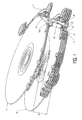
- Fig. 1 shows a stacking unit of a device for reading information stored on an information plate and/or writing information on an information plate.
- the stacking unit comprises a number of individual pigeonholes 1 to 5 shaped as flat storage compartments, An information plate 7 is present in the upper compartment 1, and an information plate 6 is present in the lower compartment 5.
- the compartments 2 to 5 are all in their respective lowermost positions, i.e. moved as far down as possible.
- the displacement of the compartments 1 to 5 in a stacking direction may take place, for example, through rotation of worm gears whose outer threads are in engagement with recesses of the respective compartments.
- the compartment 1 is in a transitional position from which a transport of the information plate 7 is possible by means of a transport mechanism which is not shown in any detail, i.e. into a playback position for playing the information plate or into an ejection position for removing the information plate from the device.
- the various compartments are transported in the stacking direction into the transitional position for the purpose of loading and unloading.
- the slope of the worm gears (not shown) in the region of the transitional position is greater than in the region of the stacking positions, with the result that the distance H between the individual compartments changes during the process of displacement inside the stacking unit.
- a detailed description of the operation of such a stacking unit is described in the document EP 0892403.
- the distance H is at its greatest in the transitional position, in which the compartment 1 is present. This creates room for the transport mechanism, which is not shown in any detail, for transporting the information plate 7 from the transitional position into an ejection or playback position.
- the distance between the individual compartments is very small in the lower stack positions in which in Fig. 1 the compartments 2 to 5 are present.
- a switching unit with an electrical switch 10, an operating lever 11, and an abutment element 9 are arranged in the peripheral region of the information plate 7.
- the operating lever 11 is rotatably journaled and comprises inlet slopes as well as another extension. The extension lies against a switching lever 10a of the electrical switch 10.
- the switch 10 supplies a switching signal to a control unit of the device which is not shown in any detail.
- a control unit of the device which is not shown in any detail.
- an unequivocal assignment signal for that individual compartment which is instantaneously in the transitional position which signal is not described in any detail here, it can thus be unequivocally detected through a simple displacement of the individual compartments inside the stacking unit which individual compartments are provided with an information plate. This is stored in an electric memory.
- the relevant compartment is to be transported into the transitional position, in which in Fig. 1 the compartment 1 is present.
- the information plate to be inserted can now be transported by means of the transport mechanism, which is not shown, from an ejection or playback position into the compartment present in the transitional position.
- the edge of the information plate operates the lever 11 in point 11a and thus switches the switch 10, from which a stop signal for controlling the transport mechanism can be derived.
- the switch 10 thus has a dual function.
- Fig. 2 shows the stacking unit of Fig. 1 with the compartments 1 to 4 being moved into the upper stack positions and the compartment 5 with the information plate 6 being in the transitional position.
- the switch 10 is just being switched by the information plate 6.
- the individual compartments 2, 3, and 4 have indeed passed the point 11 a of the contact lever on their way upwards from the lower stack positions into the upper stack positions, but the switch 10 was not operated thereby because the compartments 2, 3, and 4 are not filled with information plates.
- a device for reading information stored on an information plate and/or writing information on an information plate is provided.
- An information plate is provided in various positions to inside the device.
- One position represents an ejection position in which the information plate can be taken from the device.
- the information plate can be transported from the ejection position into a playback position on a turntable by a transport mechanism, or into a transitional position inside a stacking unit.
- the fact that a plate has reached the transitional position is detected by means of the switch 10 and the operating lever 11 in that the plate edge of the information plate presses against the tip 11a of the operating lever 11.
- the information plate can now be transported into upper stack positions or lower stack positions by means of a further transport mechanism, in particular the worm gear mechanism described with reference to Fig. 1.
- the operating lever 11 is rotatably journaled about a pivot axis. When an information plate moving down inside the stacking unit presses from above against an inlet slope, or moving up presses from below against another inlet slope, the operating lever 11 will pivot. An extension then presses against the switching lever of the switch 10, whereby a switch contact is established with the contact surface and a control signal is supplied to a control unit.
Landscapes
- Automatic Disk Changers (AREA)
Description
- The invention relates to a device for reading information stored on an information plate and/or writing information on an information plate, comprising a stacking unit for the storage of at least two information plates in storage compartments.
- Such a device is known, for example, from the document JP 8087811A. Such devices are usually called changer devices. The term information plates is understood to refer to disc-shaped information carriers, for example CDs, CD-ROMs, and DVDs.
- The information plates are stacked one above the other in individual pigeonholes. It is necessary for a reliable operation of the changer device that the control of the device should receive information as to which pigeonholes contain an information plate.
- Optical sensors are provided in the known device inside the stacking unit for the detection of the information plates, which sensors form a photoelectric barrier.
- Such optical sensors tend to become unreliable in the case of pollution. In addition, the sensor function is dependent on the optical reflection or transparency properties of the information plates.
- EP0892403 describes a changer apparatus for information discs with a stacking unit for stacking at least two information discs in at least two stacking positions, a read/write unit for reading information stored on the information discs and/or writing information on the information discs in a play position, wherein an eject position is provided in which an information disc can be removed from the apparatus, and wherein transport means are provided for the transport of the information discs from the eject position into the loading position of the stacking unit along a curve-shaped loading path, wherein the play position has been provided between the eject position and the loading position, and the loading path lies in a loading plane.
- Document JP05/242587 discloses a device for reading information stored on an information plate comprising:
- a stacking unit for the storage of at least two information plates in storage compartments ,
- the stacking unit comprises an electromechanical switching unit for detection of the information plates,
- the switching unit can be operated by the plate edges of the information plates,
- the detection of the information plates take place when the information plates are arranged in the storage compartments.
- It is an object of the invention to provide an alternative device of the kind mentioned in the opening paragraph which renders possible a reliable, failure-proof detection of the information plates inside the stacking unit.
- According to the invention, this obj ect is achieved in that the stacking unit comprises an electromechanical switching unit for detection of the information plates, and in that the switching unit can be operated by the plate edges of the information plates.
- Such an electromechanical switching unit operates very reliably, shows no tendency to fail in the case of pollution, and its function is independent of the optical reflection and transparency properties of the information plates.
- When an information plate is being transported inside the stacking unit, the electromechanical switching unit is operated by the edge of the respective passing information plate, whereby an electrical signal can be obtained from which the occupation of the individual storage compartments in the stacking unit can be concluded.
- The inlet slopes in the embodiment of the invention as claimed in
claim 2 render it possible to actuate the switching unit with a very small force, - The dimensioning of the slopes in accordance with
claim 3 renders possible a very compact construction of the stacking unit, - The advantageous embodiment of the invention as defined in
claim 3 renders it possible to utilize standard components, for example standard contact switches, for the switching unit. This is particularly favorable as regards cost price. - In the advantageous embodiment of the invention in accordance with
claim 4, the switching unit may at the same time also be utilized for ascertaining whether the information plate has fully entered the storage compartment during the process of filling the storage compartment, which is in the transitional position. Once it has fully entered the storage compartment, the information plate presses against the switching unit, from which a stop signal can be derived for switching off the transport mechanism. The switch accordingly not only has the function of detecting the occupation of the storage compartment but also a further detection function. This dual function of the switching unit implies that an additional switch can be dispensed with. - A few diagrammatically depicted embodiments of the invention will now be explained in more detail with reference to the drawing comprising Figs. 1 to 2, of which:
- Fig. 1 is a perspective view of a stacking unit of a device for reading information stored on an information plate and/or writing information on an information plate, where four individual compartments are in lower stacking positions and one individual compartment in a transitional position,
- Fig. 2 shows the stacking unit of Fig-1, with four individual compartments in upper stacking positions and one individual compartment in a transitional position,
- Fig. 1 shows a stacking unit of a device for reading information stored on an information plate and/or writing information on an information plate. The stacking unit comprises a number of individual pigeonholes 1 to 5 shaped as flat storage compartments, An
information plate 7 is present in the upper compartment 1, and aninformation plate 6 is present in thelower compartment 5. Thecompartments 2 to 5 are all in their respective lowermost positions, i.e. moved as far down as possible. The displacement of the compartments 1 to 5 in a stacking direction may take place, for example, through rotation of worm gears whose outer threads are in engagement with recesses of the respective compartments. The compartment 1 is in a transitional position from which a transport of theinformation plate 7 is possible by means of a transport mechanism which is not shown in any detail, i.e. into a playback position for playing the information plate or into an ejection position for removing the information plate from the device. The various compartments are transported in the stacking direction into the transitional position for the purpose of loading and unloading. Preferably, the slope of the worm gears (not shown) in the region of the transitional position is greater than in the region of the stacking positions, with the result that the distance H between the individual compartments changes during the process of displacement inside the stacking unit. A detailed description of the operation of such a stacking unit is described in the document EP 0892403. - The distance H is at its greatest in the transitional position, in which the compartment 1 is present. This creates room for the transport mechanism, which is not shown in any detail, for transporting the
information plate 7 from the transitional position into an ejection or playback position. By contrast, the distance between the individual compartments is very small in the lower stack positions in which in Fig. 1 thecompartments 2 to 5 are present. A switching unit with anelectrical switch 10, anoperating lever 11, and anabutment element 9 are arranged in the peripheral region of theinformation plate 7.
Theoperating lever 11 is rotatably journaled and comprises inlet slopes as well as another extension. The extension lies against a switching lever 10a of theelectrical switch 10. - When an information plate is moved up or down inside the stacking unit in the stacking direction, its outer edges slide along the inlet slopes of the
operating lever 11, whereby theoperating lever 11 is pivoted in the direction of theswitch 10. The extension thus presses against the switching lever of theswitch 10, whereby theswitch 10 is operated. The switching point of theswitch 10 is chosen such that it is switched the moment the relevant information plate lies approximately at the level ofpoint 11a of theoperating lever 11. This is true for theinformation plate 7 in Fig. 1. - The
switch 10 supplies a switching signal to a control unit of the device which is not shown in any detail. In combination with an unequivocal assignment signal for that individual compartment which is instantaneously in the transitional position, which signal is not described in any detail here, it can thus be unequivocally detected through a simple displacement of the individual compartments inside the stacking unit which individual compartments are provided with an information plate. This is stored in an electric memory. - To fill an individual compartment with an information plate, the relevant compartment is to be transported into the transitional position, in which in Fig. 1 the compartment 1 is present. The information plate to be inserted can now be transported by means of the transport mechanism, which is not shown, from an ejection or playback position into the compartment present in the transitional position. During this, the edge of the information plate operates the
lever 11 inpoint 11a and thus switches theswitch 10, from which a stop signal for controlling the transport mechanism can be derived. Theswitch 10 thus has a dual function. - Fig. 2 shows the stacking unit of Fig. 1 with the compartments 1 to 4 being moved into the upper stack positions and the
compartment 5 with theinformation plate 6 being in the transitional position. In the situation shown in Fig. 2, theswitch 10 is just being switched by theinformation plate 6. Theindividual compartments point 11 a of the contact lever on their way upwards from the lower stack positions into the upper stack positions, but theswitch 10 was not operated thereby because thecompartments - A device for reading information stored on an information plate and/or writing information on an information plate is provided. An information plate is provided in various positions to inside the device. One position represents an ejection position in which the information plate can be taken from the device. The information plate can be transported from the ejection position into a playback position on a turntable by a transport mechanism, or into a transitional position inside a stacking unit. The fact that a plate has reached the transitional position is detected by means of the
switch 10 and theoperating lever 11 in that the plate edge of the information plate presses against thetip 11a of theoperating lever 11. This switches off the transport mechanism which is in charge of the transport between the ejection/playback position and the transitional position. Starting from this transitional position, the information plate can now be transported into upper stack positions or lower stack positions by means of a further transport mechanism, in particular the worm gear mechanism described with reference to Fig. 1. - The operating
lever 11 is rotatably journaled about a pivot axis. When an information plate moving down inside the stacking unit presses from above against an inlet slope, or moving up presses from below against another inlet slope, the operatinglever 11 will pivot. An extension then presses against the switching lever of theswitch 10, whereby a switch contact is established with the contact surface and a control signal is supplied to a control unit.
Claims (5)
- A device for reading information stored on an information plate (6, 7) and/ or writing of information on an information plate (6, 7), comprising a stacking unit for the storage of at least two information plates (6, 7) in storage compartments (1, 2, 3, 4, 5), movable in a stacking direction, the stacking unit comprises an electromechanical switching unit comprising a single switch for the detection of the information plates in the storage compartments, the switching unit can be operated by the plate edges of the information plates (6, 7), the switching unit comprises an operating lever (11) with a first and a second inlet slope actuated by the edges of the information plates (6, 7).
- A device as claimed in claim 1, characterized in that the respective inclinations of the inlet slopes of the operating lever (11) on the one hand are made sufficiently great, so that the operating lever (11) does not make contact with information plates (6, 7) stored in storage positions, and in that said inclinations on the other hand are made sufficiently small, so that the friction force necessary for operating the operating lever (11) is as small as possible.
- A device as claimed in claim 1, characterized in that the operating lever (11) has an extension, which is designed for actuating a switch (10).
- A device as claimed in claim 1, characterized in that the switching unit is arranged in a transitional position of the stacking unit, from which position an information plate (6, 7) can be transported on the one hand into an ejection or playback position, and on the other hand into stacking positions of the stacking unit.
- A device as claimed in claim 1, characterized in that the switching unit is designed to supply a control signal for controlling a transport mechanism and/or for storing the occupation data of the storage compartments (1, 2, 3, 4, 5) of the stacking unit in an electronic storage medium.
Applications Claiming Priority (3)
| Application Number | Priority Date | Filing Date | Title |
|---|---|---|---|
| DE19910661A DE19910661A1 (en) | 1999-03-11 | 1999-03-11 | Detection device for occupancy detection of a changer device |
| DE19910661 | 1999-03-11 | ||
| PCT/EP2000/002179 WO2000054271A1 (en) | 1999-03-11 | 2000-03-10 | Stacking unit for an electronic device |
Publications (2)
| Publication Number | Publication Date |
|---|---|
| EP1076901A1 EP1076901A1 (en) | 2001-02-21 |
| EP1076901B1 true EP1076901B1 (en) | 2006-09-27 |
Family
ID=7900464
Family Applications (1)
| Application Number | Title | Priority Date | Filing Date |
|---|---|---|---|
| EP00922515A Expired - Lifetime EP1076901B1 (en) | 1999-03-11 | 2000-03-10 | Stacking unit for an electronic device |
Country Status (6)
| Country | Link |
|---|---|
| US (1) | US6600701B1 (en) |
| EP (1) | EP1076901B1 (en) |
| JP (1) | JP2002539574A (en) |
| KR (1) | KR100698485B1 (en) |
| DE (2) | DE19910661A1 (en) |
| WO (1) | WO2000054271A1 (en) |
Citations (1)
| Publication number | Priority date | Publication date | Assignee | Title |
|---|---|---|---|---|
| EP0892403A1 (en) * | 1997-06-11 | 1999-01-20 | Philips Patentverwaltung GmbH | Disc changer |
Family Cites Families (5)
| Publication number | Priority date | Publication date | Assignee | Title |
|---|---|---|---|---|
| JPH02292773A (en) * | 1989-05-02 | 1990-12-04 | Pioneer Electron Corp | Player for housing plural disks |
| US5276668A (en) * | 1990-02-02 | 1994-01-04 | Clarion Co., Ltd. | Compact disk selecting mechanism including mechanical and optical detection |
| JPH05242587A (en) * | 1992-02-29 | 1993-09-21 | Suzuki Motor Corp | Multi-play CD changer device |
| JPH0887811A (en) | 1994-09-15 | 1996-04-02 | Sony Corp | changer |
| JP2901512B2 (en) * | 1995-02-27 | 1999-06-07 | 株式会社ケンウッド | Recording medium playback device |
-
1999
- 1999-03-11 DE DE19910661A patent/DE19910661A1/en not_active Withdrawn
-
2000
- 2000-03-10 US US09/674,671 patent/US6600701B1/en not_active Expired - Fee Related
- 2000-03-10 DE DE60030922T patent/DE60030922T2/en not_active Expired - Fee Related
- 2000-03-10 EP EP00922515A patent/EP1076901B1/en not_active Expired - Lifetime
- 2000-03-10 WO PCT/EP2000/002179 patent/WO2000054271A1/en not_active Ceased
- 2000-03-10 JP JP2000604415A patent/JP2002539574A/en not_active Withdrawn
- 2000-03-10 KR KR1020007012517A patent/KR100698485B1/en not_active Expired - Fee Related
Patent Citations (1)
| Publication number | Priority date | Publication date | Assignee | Title |
|---|---|---|---|---|
| EP0892403A1 (en) * | 1997-06-11 | 1999-01-20 | Philips Patentverwaltung GmbH | Disc changer |
Also Published As
| Publication number | Publication date |
|---|---|
| US6600701B1 (en) | 2003-07-29 |
| EP1076901A1 (en) | 2001-02-21 |
| JP2002539574A (en) | 2002-11-19 |
| WO2000054271A1 (en) | 2000-09-14 |
| DE19910661A1 (en) | 2000-09-14 |
| KR100698485B1 (en) | 2007-03-23 |
| DE60030922D1 (en) | 2006-11-09 |
| KR20010043465A (en) | 2001-05-25 |
| DE60030922T2 (en) | 2007-05-24 |
Similar Documents
| Publication | Publication Date | Title |
|---|---|---|
| JP4260081B2 (en) | Disc device, disc check method, eject method and loading method in disc device | |
| US6600701B1 (en) | Stacking unit for an electronic device with electromechanical switching unit | |
| EP0833327A1 (en) | Disc package | |
| JP2009297402A (en) | Premium put-out device | |
| KR0180906B1 (en) | Disc reproduction apparatus having disc change function | |
| US6883174B1 (en) | Read/write device for an information plate with load/unload mechanism | |
| US7257825B2 (en) | Disc changer, method of detecting mode thereof, and method of selecting disc ejection | |
| JP2721800B2 (en) | Disc changer | |
| EP1076900B1 (en) | Changer device for disc-shaped data carriers | |
| JP2731111B2 (en) | Clamp support structure | |
| EP1847993B1 (en) | Optical disc device | |
| JP2011048891A (en) | Disk device with sliders between which space is increased by disk being carried | |
| JP3441290B2 (en) | Disk autochanger device | |
| JP5441492B2 (en) | Disk unit | |
| JP2756412B2 (en) | Pickup unit support structure | |
| JP3870377B2 (en) | Disc ejector selection device for disc changer | |
| JP2004355745A (en) | Device and method for detecting mode for disk changer | |
| JP2706045B2 (en) | Mis-insertion detection structure of disk stocker | |
| JP2007102883A (en) | Disk drive | |
| JP3648977B2 (en) | Disc changer device | |
| JP2006012252A (en) | Disk device, and method for preventing simultaneous insertion of two disks therein | |
| JPH0748290B2 (en) | Disk playback method | |
| JPH0765562A (en) | Lid opening / closing mechanism | |
| JP2007102937A (en) | Disk drive | |
| JPH0684544U (en) | Disc position detecting device in disc reproducing device |
Legal Events
| Date | Code | Title | Description |
|---|---|---|---|
| PUAI | Public reference made under article 153(3) epc to a published international application that has entered the european phase |
Free format text: ORIGINAL CODE: 0009012 |
|
| AK | Designated contracting states |
Kind code of ref document: A1 Designated state(s): AT BE CH CY DE DK ES FI FR GB GR IE IT LI LU MC NL PT SE |
|
| 17P | Request for examination filed |
Effective date: 20010314 |
|
| RAP1 | Party data changed (applicant data changed or rights of an application transferred) |
Owner name: KONINKLIJKE PHILIPS ELECTRONICS N.V. Owner name: PHILIPS CORPORATE INTELLECTUAL PROPERTY GMBH |
|
| RAP1 | Party data changed (applicant data changed or rights of an application transferred) |
Owner name: PHILIPS INTELLECTUAL PROPERTY & STANDARDS GMBH Owner name: KONINKLIJKE PHILIPS ELECTRONICS N.V. |
|
| RBV | Designated contracting states (corrected) |
Designated state(s): DE FR GB IT |
|
| 17Q | First examination report despatched |
Effective date: 20050503 |
|
| GRAP | Despatch of communication of intention to grant a patent |
Free format text: ORIGINAL CODE: EPIDOSNIGR1 |
|
| GRAS | Grant fee paid |
Free format text: ORIGINAL CODE: EPIDOSNIGR3 |
|
| GRAA | (expected) grant |
Free format text: ORIGINAL CODE: 0009210 |
|
| AK | Designated contracting states |
Kind code of ref document: B1 Designated state(s): DE FR GB IT |
|
| PG25 | Lapsed in a contracting state [announced via postgrant information from national office to epo] |
Ref country code: IT Free format text: LAPSE BECAUSE OF FAILURE TO SUBMIT A TRANSLATION OF THE DESCRIPTION OR TO PAY THE FEE WITHIN THE PRE;WARNING: LAPSES OF ITALIAN PATENTS WITH EFFECTIVE DATE BEFORE 2007 MAY HAVE OCCURRED AT ANY TIME BEFORE 2007. THE CORRECT EFFECTIVE DATE MAY BE DIFFERENT FROM THE ONE RECORDED.SCRIBED TIME-LIMIT Effective date: 20060927 |
|
| REG | Reference to a national code |
Ref country code: GB Ref legal event code: FG4D |
|
| REF | Corresponds to: |
Ref document number: 60030922 Country of ref document: DE Date of ref document: 20061109 Kind code of ref document: P |
|
| PGFP | Annual fee paid to national office [announced via postgrant information from national office to epo] |
Ref country code: GB Payment date: 20070327 Year of fee payment: 8 |
|
| ET | Fr: translation filed | ||
| PGFP | Annual fee paid to national office [announced via postgrant information from national office to epo] |
Ref country code: DE Payment date: 20070516 Year of fee payment: 8 |
|
| PLBE | No opposition filed within time limit |
Free format text: ORIGINAL CODE: 0009261 |
|
| STAA | Information on the status of an ep patent application or granted ep patent |
Free format text: STATUS: NO OPPOSITION FILED WITHIN TIME LIMIT |
|
| 26N | No opposition filed |
Effective date: 20070628 |
|
| PGFP | Annual fee paid to national office [announced via postgrant information from national office to epo] |
Ref country code: IT Payment date: 20070629 Year of fee payment: 8 |
|
| PGFP | Annual fee paid to national office [announced via postgrant information from national office to epo] |
Ref country code: FR Payment date: 20070329 Year of fee payment: 8 |
|
| GBPC | Gb: european patent ceased through non-payment of renewal fee |
Effective date: 20080310 |
|
| REG | Reference to a national code |
Ref country code: FR Ref legal event code: ST Effective date: 20081125 |
|
| PG25 | Lapsed in a contracting state [announced via postgrant information from national office to epo] |
Ref country code: DE Free format text: LAPSE BECAUSE OF NON-PAYMENT OF DUE FEES Effective date: 20081001 |
|
| PG25 | Lapsed in a contracting state [announced via postgrant information from national office to epo] |
Ref country code: FR Free format text: LAPSE BECAUSE OF NON-PAYMENT OF DUE FEES Effective date: 20080331 |
|
| PG25 | Lapsed in a contracting state [announced via postgrant information from national office to epo] |
Ref country code: GB Free format text: LAPSE BECAUSE OF NON-PAYMENT OF DUE FEES Effective date: 20080310 |
|
| PG25 | Lapsed in a contracting state [announced via postgrant information from national office to epo] |
Ref country code: IT Free format text: LAPSE BECAUSE OF NON-PAYMENT OF DUE FEES Effective date: 20080310 |