EP1076757B1 - Method and apparatus for sealing between casing and wellhead connector structure - Google Patents
Method and apparatus for sealing between casing and wellhead connector structure Download PDFInfo
- Publication number
- EP1076757B1 EP1076757B1 EP99921801A EP99921801A EP1076757B1 EP 1076757 B1 EP1076757 B1 EP 1076757B1 EP 99921801 A EP99921801 A EP 99921801A EP 99921801 A EP99921801 A EP 99921801A EP 1076757 B1 EP1076757 B1 EP 1076757B1
- Authority
- EP
- European Patent Office
- Prior art keywords
- casing
- head
- bushing
- metal
- seal
- Prior art date
- Legal status (The legal status is an assumption and is not a legal conclusion. Google has not performed a legal analysis and makes no representation as to the accuracy of the status listed.)
- Expired - Lifetime
Links
- 238000007789 sealing Methods 0.000 title claims description 24
- 238000000034 method Methods 0.000 title claims description 20
- 239000002184 metal Substances 0.000 claims description 47
- 229910052751 metal Inorganic materials 0.000 claims description 47
- 238000012360 testing method Methods 0.000 claims description 3
- 238000002360 preparation method Methods 0.000 claims description 2
- 229910001220 stainless steel Inorganic materials 0.000 claims description 2
- 239000010935 stainless steel Substances 0.000 claims description 2
- 230000013011 mating Effects 0.000 claims 2
- 230000002093 peripheral effect Effects 0.000 claims 2
- 210000003128 head Anatomy 0.000 description 81
- 238000009434 installation Methods 0.000 description 9
- 239000004519 grease Substances 0.000 description 5
- RYGMFSIKBFXOCR-UHFFFAOYSA-N Copper Chemical compound [Cu] RYGMFSIKBFXOCR-UHFFFAOYSA-N 0.000 description 3
- 239000003638 chemical reducing agent Substances 0.000 description 3
- 229910052802 copper Inorganic materials 0.000 description 3
- 239000010949 copper Substances 0.000 description 3
- 238000005259 measurement Methods 0.000 description 3
- 241000191291 Abies alba Species 0.000 description 2
- 239000004215 Carbon black (E152) Substances 0.000 description 2
- 239000008186 active pharmaceutical agent Substances 0.000 description 2
- 229930195733 hydrocarbon Natural products 0.000 description 2
- 150000002430 hydrocarbons Chemical class 0.000 description 2
- 238000003754 machining Methods 0.000 description 2
- 238000012986 modification Methods 0.000 description 2
- 230000004048 modification Effects 0.000 description 2
- XQCFHQBGMWUEMY-ZPUQHVIOSA-N Nitrovin Chemical compound C=1C=C([N+]([O-])=O)OC=1\C=C\C(=NNC(=N)N)\C=C\C1=CC=C([N+]([O-])=O)O1 XQCFHQBGMWUEMY-ZPUQHVIOSA-N 0.000 description 1
- 230000006978 adaptation Effects 0.000 description 1
- 239000010953 base metal Substances 0.000 description 1
- 230000005574 cross-species transmission Effects 0.000 description 1
- 210000000887 face Anatomy 0.000 description 1
- 239000012530 fluid Substances 0.000 description 1
- 238000004519 manufacturing process Methods 0.000 description 1
- 238000003825 pressing Methods 0.000 description 1
- 238000010998 test method Methods 0.000 description 1
- 230000000007 visual effect Effects 0.000 description 1
Images




Classifications
-
- E—FIXED CONSTRUCTIONS
- E21—EARTH OR ROCK DRILLING; MINING
- E21B—EARTH OR ROCK DRILLING; OBTAINING OIL, GAS, WATER, SOLUBLE OR MELTABLE MATERIALS OR A SLURRY OF MINERALS FROM WELLS
- E21B33/00—Sealing or packing boreholes or wells
- E21B33/02—Surface sealing or packing
- E21B33/03—Well heads; Setting-up thereof
-
- E—FIXED CONSTRUCTIONS
- E21—EARTH OR ROCK DRILLING; MINING
- E21B—EARTH OR ROCK DRILLING; OBTAINING OIL, GAS, WATER, SOLUBLE OR MELTABLE MATERIALS OR A SLURRY OF MINERALS FROM WELLS
- E21B33/00—Sealing or packing boreholes or wells
- E21B33/02—Surface sealing or packing
- E21B33/03—Well heads; Setting-up thereof
- E21B33/04—Casing heads; Suspending casings or tubings in well heads
-
- E—FIXED CONSTRUCTIONS
- E21—EARTH OR ROCK DRILLING; MINING
- E21B—EARTH OR ROCK DRILLING; OBTAINING OIL, GAS, WATER, SOLUBLE OR MELTABLE MATERIALS OR A SLURRY OF MINERALS FROM WELLS
- E21B33/00—Sealing or packing boreholes or wells
- E21B33/02—Surface sealing or packing
- E21B33/03—Well heads; Setting-up thereof
- E21B33/04—Casing heads; Suspending casings or tubings in well heads
- E21B33/0422—Casing heads; Suspending casings or tubings in well heads a suspended tubing or casing being gripped by a slip or an internally serrated member
-
- E—FIXED CONSTRUCTIONS
- E21—EARTH OR ROCK DRILLING; MINING
- E21B—EARTH OR ROCK DRILLING; OBTAINING OIL, GAS, WATER, SOLUBLE OR MELTABLE MATERIALS OR A SLURRY OF MINERALS FROM WELLS
- E21B2200/00—Special features related to earth drilling for obtaining oil, gas or water
- E21B2200/01—Sealings characterised by their shape
Definitions
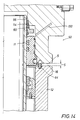
- a relatively soft metal seal is positioned over the upper end of the casing stub and is moved downwardly until it abuts the cam ring.
- a tubing head or similar device such as a spool or adapter for a Christmas tree, is positioned over the upper end of the casing stub such that it lands on the exterior profile of the seal.
- a measurement is made of the distance between the bottom surface of the tubing head and the top surface of the casing head. The tubing head is removed, and the seal is removed.
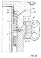
- a connector squeezes a lower flange of the tubing head and an upper flange of the casing head together, thereby causing the flange faces of the tubing head and the casing head to abut each other.
- the tubing head moves down by the predetermined distance referred to above while a camming surface of the tubing head drives the soft metal-to-metal seal radially inwardly into the casing stub.
- the seal is prevented from axial movement along the casing stub, because the slip ring, cam ring and shim cannot move axially due to the fact that the slip ring tightly grips the exterior of the casing stub.
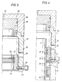
- Another feature of the invention relates to the use of a swaging tool which is used to position the bushing and the slips at a precise location relative to the hub face of the casing head thereby providing accurate positioning of the slip assembly to insure later adequate energizing of the metal seal on the casing stub after a shimming procedure and after makeup of a connector between the tubing head and the casing head.
- Figures 2 and 3 illustrate the swaging tool which includes a lower tool housing 19 having a visual port 26 provided therein.
- An upper tool housing 28 is threadably secured to lower tool housing 19.
- Three one hundred sixty degree pad eyes 32 are provided for lifting the swaging tool 18 onto and from casing stub 11.
- a piston 30 is provided within the upper tool housing 28, and a sealing polypak 36 provides a seal for piston 36 to be reciprocated by pressurized hydraulic fluid.
- the piston 30 of the swaging tool 18 is placed as high as possible in the upper tool housing 28.
- a pipe plug 34 is installed in pressure port 35 to maintain the piston 30 in place.
- tubing head 50 and the FX RCMS seal element 54 are removed. Shims 60 that were selected as described above are installed between seal 54 and cam bowl 42. A stand off gap S of about 0.89 cm (350") is preferred. The number of shims to install is found by subtracting the measurement recorded above from 0.89 cm (.350”) and determining the number of 0.38 cm and 0.25 cm (.150 " and .100 ") shims required for a minimum gap of 0.89 cm (.350”)
Landscapes
- Geology (AREA)
- Life Sciences & Earth Sciences (AREA)
- Engineering & Computer Science (AREA)
- Mining & Mineral Resources (AREA)
- Environmental & Geological Engineering (AREA)
- Fluid Mechanics (AREA)
- Physics & Mathematics (AREA)
- General Life Sciences & Earth Sciences (AREA)
- Geochemistry & Mineralogy (AREA)
- Earth Drilling (AREA)
- Excavating Of Shafts Or Tunnels (AREA)
- Sealing Devices (AREA)
- Connector Housings Or Holding Contact Members (AREA)
Description
| CSG. TOL. RANGE W/CORRESPONDING SLIPS, BOWL, SHIM AND FX RCMS SEAL | ||||||||
| CSG SIZE (INCHES) | LOW TOL. SHIM | GAGE #1 | GAGE #2 | GAGE #3 | SLIPS | BOWL | SHIM | SEAL |
| 9.721/9.685 | NO GO | NO GO (1) | NO GO | NO GO | HIGH TOL. | #1 | HIGH TOL. | HIGH TOL. |
| 9.684/9.649 | NO GO | GO | NO GO (1) | NO GO | HIGH TOL. | #2 | HIGH TOL. | HIGH TOL. |
| 9.648/9.613 | GO | GO | GO | NO GO (1) | LOW TOL. | #3 | LOW TOL. | LOW TOL. |
| 9.612/9.577 | GO | GO | GO | GO | LOW TOL. | #4 | LOW TOL. | LOW TOL. |
| NOTE 1:- IF GAGE GOES OVER THE CASING, ASSUME THE CASING IS IN THE NEXT LOWER TOLERANCE RANGE. | ||||||||
| GAGE SIZES:- LOW TOL. SHIM ID 9.663 "/9.673 " = 2454 mm / 2457 mm GAGE #1 ID 9.686 "/9.687 " = 2459 mm / 2460 mm GAGE #2 ID 9.650 "/9.651" = 2451 mm / 2452 mm GAGE#3 ID 9.614"/9.615" = 2441 mm / 2442mm |
Claims (11)
- A method of installing an annular metal seal (54) about the outer rough surface of a metal casing stub (11) projecting upwardly above a casing head (12), said method characterized by the steps of:installing a bushing (22) around said outer rough surface of said casing at a position above said casing head (12);positioning a slip mechanism (40) about the outer periphery of said casing (11) for support from a top surface of said bushing (22), said slip mechanism having a gripping face which engages the casing (11);positioning a cam member (42) about a cam surface of said slip mechanism in preparation for engaging the slip mechanism (40) to urge the slip mechanism into biting engagement with the outer surface of the casing;exerting a downward force against the cam member to cam said slip mechanism inwardly into tight gripping relation with the casing with downward movement of the slip mechanism (40) resisted by the said bushing;next, positioning a metal seal (54) over the end of said casing (11) with axial support of said metal seal (54) by said slip mechanism (40); andnext mounting a tubing head or spool (50) about said outer rough surface of said casing (11) and connecting said tubing head or spool (50) to said casing head (12) with an inner peripheral surface of said tubing head or spool (50) engaging said metal seal (54) to deform and force said seal radially into sealing relation with the outer surface of said casing (11).
- The method of claim 1 wherein,
said metal seal (54) is fabricated of relatively soft metal, relative to the casing. - The method of claim 2 wherein,
said metal seal (54) is fabricated of stainless steel AISI 316 and is characterized by UNS name of 531,600 with Rockwell "B" of 83HRB Max and a yield strength of 206,850 kPa (30,000 psi) min. - The method of any of claims 1 to 3, wherein the slip and cam positioning steps comprise:positioning a slip installing tool (18) having a push ring (44) over the upper end of said projecting casing (11) onto said casing head (12) with said push ring (44) engaging said cam member (42), andforcing said cam member (42) downwardly with said slip installing tool (18) for moving said slips (40) inwardly to grip said casing (11) with the cam member (42) remaining in position adjacent the slips; then, removing the slip installing tool (18) from the upper end of said casing (11) while the slips (40) and said cam member (42) remain in position on said casing (11).
- The method of claim 4, comprising the further steps of;
prior to connecting a lower end of said tubing head or spool (50) to an upper end of said casing head (12), measuring the axial distance between the bottom end of said tubing head or spool (5) and the top end of said casing head (12);
then removing said tubing head or spool (50) from said casing (11);
placing at least one shim (60) between said metal seal (54) and said cam member (42) to ensure that the bottom end of said tubing head or spool (50) and the top end of said casing head (12) is separated by a predetermined axial distance; and
again placing said tubing head or spool (50) over the upper end of said casing (11). - The method of claim 4, wherein,
when said cam member (42) is forced downwardly for camming said slips (40) radially inward toward said casing (11), said bushing (22) axially supports said slips and limits axial movement of the cam member (42) during the camming action. - The method of claim 4, further including the steps of;
installing screws (24) on said slip installing tool (18) for said bushing (22); and
actuating said screws (24) to engage said bushing (22) and position said bushing (22) accurately on said casing (11). - A metal-to-metal sealing arrangement for sealing about the outer rough surface of a casing stub (11) projecting from the upper end of a casing head (12); the metal seal arranged and designed to be energized for sealing between the casing and a tubing head or spool (50) mounted on the casing head after the metal seal has been positioned on the casing; said sealing arrangement characterized by:whereby when said tubing head or spool (50) is positioned over the casing (11) and abutting the casing head (12), it provides an inner peripheral sealing surface (96) in contact with said metal seal (54) to deform and force said metal seal against the rough outer surface of the casing (18) while said seal is carried by said slip mechanism (40).a slip mechanism (40) having a gripping face which engages the casing;a cam member (42) arranged and designed to force the slip mechanism (40) radially into engagement with said casing (11) when forced downwardly toward said casing head (12);a metal seal (54) positioned about the casing (11) above the slip mechanism (40) and carried by the slip mechanism (40);
- The metal-to-metal sealing arrangement of claim 8, wherein,
said tubing head or spool (50) and said casing head (12) have mating flanges (16, 5); and a fastener (60) clamps said mating flanges together. - The metal-to-metal sealing arrangement of claim 8, further comprising,
a bushing (22) mounted about said casing (11) for supporting said slip mechanism (40) when said slip mechanism (40) is forced inwardly to grip said casing (11) when said cam member (42) is forced downwardly, said bushing (22) being positioned in an annular space between said casing (11) and said tubing head or spool (50), said bushing (22) also providing a second sealing member for testing of said metal seal (54). - The metal-to-metal sealing arrangement of claim 10, wherein,
said bushing (22) is coupled to said casing head (12) during camming of said slip mechanism by said cam member (42) into gripping relation thereby to oppose the forces exerted by the camming action.
Applications Claiming Priority (6)
| Application Number | Priority Date | Filing Date | Title |
|---|---|---|---|
| US8475098P | 1998-05-08 | 1998-05-08 | |
| US306525P | 1999-05-06 | ||
| US09/306,525 US5996695A (en) | 1998-05-08 | 1999-05-07 | Method and apparatus for sealing between casing and wellhead connector structure |
| PCT/US1999/010117 WO1999058813A1 (en) | 1998-05-08 | 1999-05-07 | Method and apparatus for sealing between casing and wellhead connector structure |
| 2003-03-28 | |||
| US84750P | 2008-07-30 |
Publications (3)
| Publication Number | Publication Date |
|---|---|
| EP1076757A1 EP1076757A1 (en) | 2001-02-21 |
| EP1076757A4 EP1076757A4 (en) | 2001-10-31 |
| EP1076757B1 true EP1076757B1 (en) | 2003-01-15 |
Family
ID=26771380
Family Applications (1)
| Application Number | Title | Priority Date | Filing Date |
|---|---|---|---|
| EP99921801A Expired - Lifetime EP1076757B1 (en) | 1998-05-08 | 1999-05-07 | Method and apparatus for sealing between casing and wellhead connector structure |
Country Status (7)
| Country | Link |
|---|---|
| US (1) | US5996695A (en) |
| EP (1) | EP1076757B1 (en) |
| AU (1) | AU3891699A (en) |
| BR (1) | BR9910475A (en) |
| CA (1) | CA2330105C (en) |
| NO (1) | NO318156B1 (en) |
| WO (1) | WO1999058813A1 (en) |
Cited By (1)
| Publication number | Priority date | Publication date | Assignee | Title |
|---|---|---|---|---|
| US12503922B2 (en) | 2023-11-21 | 2025-12-23 | Saudi Arabian Oil Company | Connection device for casing stubs |
Families Citing this family (30)
| Publication number | Priority date | Publication date | Assignee | Title |
|---|---|---|---|---|
| US5950645A (en) | 1993-10-20 | 1999-09-14 | Verteq, Inc. | Semiconductor wafer cleaning system |
| US6662868B1 (en) | 2000-05-03 | 2003-12-16 | Bernard H. Van Bilderbeek | Clamping well casings |
| US6557644B1 (en) * | 2001-07-31 | 2003-05-06 | Kvaerner Oilfield Products, Inc. | Adjustable tubing hanger assembly |
| MXPA06005932A (en) | 2001-10-25 | 2007-05-07 | Pleux Ocean Systems Ltd | Clamping well casings. |
| US6834718B2 (en) * | 2001-12-21 | 2004-12-28 | Stream-Flo Industries, Ltd. | Casing head connector with landing base |
| US7740061B2 (en) * | 2003-12-31 | 2010-06-22 | Plexus Ocean Systems Ltd. | Externally activated seal system for wellhead |
| US7128143B2 (en) * | 2003-12-31 | 2006-10-31 | Plexus Ocean Systems Ltd. | Externally activated seal system for wellhead |
| US7395867B2 (en) * | 2004-03-17 | 2008-07-08 | Stinger Wellhead Protection, Inc. | Hybrid wellhead system and method of use |
| US20050242519A1 (en) * | 2004-04-29 | 2005-11-03 | Koleilat Bashir M | Wedge seal |
| FR2870312B1 (en) * | 2004-05-11 | 2006-07-07 | Arkema Sa | DEVICE FOR SEALING A PENETRATING TUBE INTO A RESERVOIR |
| US7165980B2 (en) * | 2004-05-13 | 2007-01-23 | Thomas & Betts International, Inc. | Conduit bushing with revolving lug |
| US8196649B2 (en) | 2006-11-28 | 2012-06-12 | T-3 Property Holdings, Inc. | Thru diverter wellhead with direct connecting downhole control |
| CA2581581C (en) | 2006-11-28 | 2014-04-29 | T-3 Property Holdings, Inc. | Direct connecting downhole control system |
| BRPI0818017B1 (en) * | 2007-10-25 | 2018-09-25 | Cameron Int Corp | annular seal configuration tool and method for configuring an annular seal |
| US7779921B2 (en) * | 2007-10-26 | 2010-08-24 | Weatherford/Lamb, Inc. | Wellhead completion assembly capable of versatile arrangements |
| CA2643800C (en) * | 2007-11-13 | 2015-02-03 | Stream-Flo Industries Ltd. | Casing head slip lock connection for high temperature service |
| BRPI0820220B1 (en) | 2007-11-21 | 2018-08-14 | Cameron International Corporation | COUNTERPRESSION SYSTEM AND METHOD OF OPERATING A COUNTERPRESSION VALVE |
| WO2013152033A1 (en) * | 2012-04-02 | 2013-10-10 | Array Holdings, Inc. | Energized bushing seal |
| US9725969B2 (en) | 2014-07-08 | 2017-08-08 | Cameron International Corporation | Positive lock system |
| US9970252B2 (en) | 2014-10-14 | 2018-05-15 | Cameron International Corporation | Dual lock system |
| US10156112B2 (en) * | 2015-12-29 | 2018-12-18 | Cameron International Corporation | Hybrid wellhead connector |
| WO2017181051A1 (en) | 2016-04-14 | 2017-10-19 | The Colex Group, Inc. | Valve apparatus |
| US11105451B2 (en) * | 2017-07-07 | 2021-08-31 | Eaton Intelligent Power Limited | Heat transfer interruption for improved fire resistance/proof performance |
| WO2019055482A1 (en) | 2017-09-12 | 2019-03-21 | Downing Wellhead Equipment, Llc | Installing multiple tubular strings through blowout preventer |
| US10689938B2 (en) | 2017-12-14 | 2020-06-23 | Downing Wellhead Equipment, Llc | Subterranean formation fracking and well workover |
| GB2571957B (en) | 2018-03-14 | 2020-05-13 | Downhole Tools International Ltd | Apparatus for connecting a tool string to coiled tubing in downhole operations |
| CN115596392B (en) * | 2022-10-27 | 2025-09-12 | 盐城神华机械制造有限公司 | Sealing device and casing head |
| CN115807643B (en) * | 2022-11-29 | 2025-09-12 | 盐城神华机械制造有限公司 | A casing head shell |
| US12331606B2 (en) | 2023-07-18 | 2025-06-17 | Downing Wellhead Equipment, Llc | Apparatus including slip cartridge and associated methods for tubular string |
| US12595713B1 (en) * | 2024-10-04 | 2026-04-07 | Fmc Technologies, Inc. | Externally pressure-testable connector assembly |
Family Cites Families (6)
| Publication number | Priority date | Publication date | Assignee | Title |
|---|---|---|---|---|
| US1926856A (en) * | 1933-03-24 | 1933-09-12 | Nat Supply Co | Casing head |
| US3438654A (en) * | 1964-05-04 | 1969-04-15 | Bank Of Southwest Nat Ass | Well completion apparatus |
| US4646845A (en) * | 1984-08-14 | 1987-03-03 | Cactus Wellhead Equipment Co., Inc. | Metal seal for wellhead apparatus |
| US5205356A (en) * | 1990-12-27 | 1993-04-27 | Abb Vetco Gray Inc. | Well starter head |
| US5257792A (en) * | 1991-10-15 | 1993-11-02 | Fip Incorporated | Well head metal seal |
| US5332043A (en) * | 1993-07-20 | 1994-07-26 | Abb Vetco Gray Inc. | Wellhead connector |
-
1999
- 1999-05-07 BR BR9910475-0A patent/BR9910475A/en not_active IP Right Cessation
- 1999-05-07 CA CA002330105A patent/CA2330105C/en not_active Expired - Fee Related
- 1999-05-07 WO PCT/US1999/010117 patent/WO1999058813A1/en not_active Ceased
- 1999-05-07 US US09/306,525 patent/US5996695A/en not_active Expired - Lifetime
- 1999-05-07 AU AU38916/99A patent/AU3891699A/en not_active Abandoned
- 1999-05-07 EP EP99921801A patent/EP1076757B1/en not_active Expired - Lifetime
-
2000
- 2000-10-30 NO NO20005464A patent/NO318156B1/en not_active Application Discontinuation
Cited By (1)
| Publication number | Priority date | Publication date | Assignee | Title |
|---|---|---|---|---|
| US12503922B2 (en) | 2023-11-21 | 2025-12-23 | Saudi Arabian Oil Company | Connection device for casing stubs |
Also Published As
| Publication number | Publication date |
|---|---|
| AU3891699A (en) | 1999-11-29 |
| CA2330105C (en) | 2004-12-14 |
| CA2330105A1 (en) | 1999-11-18 |
| BR9910475A (en) | 2001-09-04 |
| NO20005464D0 (en) | 2000-10-30 |
| US5996695A (en) | 1999-12-07 |
| WO1999058813A1 (en) | 1999-11-18 |
| EP1076757A4 (en) | 2001-10-31 |
| NO20005464L (en) | 2000-12-06 |
| EP1076757A1 (en) | 2001-02-21 |
| NO318156B1 (en) | 2005-02-07 |
Similar Documents
| Publication | Publication Date | Title |
|---|---|---|
| CA2330105C (en) | Method and apparatus for sealing between casing and wellhead connector structure | |
| EP0289108B1 (en) | Wellhead hanger and seal | |
| US4936382A (en) | Drive pipe adaptor | |
| CA2128177C (en) | Wellhead connector | |
| US4553591A (en) | Oil well drilling apparatus | |
| US5524710A (en) | Hanger assembly | |
| CA1218298A (en) | Subsea casing hanger suspension system | |
| US5107931A (en) | Temporary abandonment cap and tool | |
| US8272433B2 (en) | Wellhead isolation tool and wellhead assembly incorporating the same | |
| US4886121A (en) | Universal flexbowl wellhead and well completion method | |
| GB2299104A (en) | Tubing hangers | |
| CA2201554A1 (en) | Tree test plug | |
| US5725056A (en) | Wellhead assembly with removable bowl adapter | |
| US7455105B1 (en) | Apparatus and method for installing coiled tubing in a well | |
| US20040182611A1 (en) | Heavy load carry slips and method | |
| US4942924A (en) | Liner setting assembly and method | |
| US5261493A (en) | Method of testing snap type pipe connectors | |
| US4214778A (en) | Holddown mechanism for a tubing hanger in a wellhead | |
| US7493944B2 (en) | Wellhead isolation tool and method of fracturing a well | |
| USRE34071E (en) | Surface wellhead | |
| US4559809A (en) | Process of testing blow-out preventer without pulling the wear bushing | |
| US20030121653A1 (en) | Casing head connector with landing base | |
| US6588510B2 (en) | Coil tubing hanger system | |
| US4892149A (en) | Method of securing a tubular member within an annular well member, the combined well structure and the tool | |
| US20030047319A1 (en) | Mechanical torque table and method |
Legal Events
| Date | Code | Title | Description |
|---|---|---|---|
| PUAI | Public reference made under article 153(3) epc to a published international application that has entered the european phase |
Free format text: ORIGINAL CODE: 0009012 |
|
| 17P | Request for examination filed |
Effective date: 20001030 |
|
| AK | Designated contracting states |
Kind code of ref document: A1 Designated state(s): FR GB |
|
| A4 | Supplementary search report drawn up and despatched |
Effective date: 20010914 |
|
| AK | Designated contracting states |
Kind code of ref document: A4 Designated state(s): FR GB |
|
| RIC1 | Information provided on ipc code assigned before grant |
Free format text: 7E 21B 33/04 A, 7E 21B 33/03 B |
|
| 17Q | First examination report despatched |
Effective date: 20011126 |
|
| GRAG | Despatch of communication of intention to grant |
Free format text: ORIGINAL CODE: EPIDOS AGRA |
|
| GRAG | Despatch of communication of intention to grant |
Free format text: ORIGINAL CODE: EPIDOS AGRA |
|
| GRAH | Despatch of communication of intention to grant a patent |
Free format text: ORIGINAL CODE: EPIDOS IGRA |
|
| GRAH | Despatch of communication of intention to grant a patent |
Free format text: ORIGINAL CODE: EPIDOS IGRA |
|
| RAP1 | Party data changed (applicant data changed or rights of an application transferred) |
Owner name: FMC TECHNOLOGIES, INC. |
|
| GRAA | (expected) grant |
Free format text: ORIGINAL CODE: 0009210 |
|
| AK | Designated contracting states |
Kind code of ref document: B1 Designated state(s): FR GB |
|
| REG | Reference to a national code |
Ref country code: GB Ref legal event code: FG4D |
|
| ET | Fr: translation filed | ||
| PLBE | No opposition filed within time limit |
Free format text: ORIGINAL CODE: 0009261 |
|
| STAA | Information on the status of an ep patent application or granted ep patent |
Free format text: STATUS: NO OPPOSITION FILED WITHIN TIME LIMIT |
|
| 26N | No opposition filed |
Effective date: 20031016 |
|
| REG | Reference to a national code |
Ref country code: FR Ref legal event code: PLFP Year of fee payment: 18 |
|
| REG | Reference to a national code |
Ref country code: FR Ref legal event code: PLFP Year of fee payment: 19 |
|
| REG | Reference to a national code |
Ref country code: FR Ref legal event code: PLFP Year of fee payment: 20 |
|
| PGFP | Annual fee paid to national office [announced via postgrant information from national office to epo] |
Ref country code: GB Payment date: 20180329 Year of fee payment: 20 |
|
| PGFP | Annual fee paid to national office [announced via postgrant information from national office to epo] |
Ref country code: FR Payment date: 20180411 Year of fee payment: 20 |
|
| REG | Reference to a national code |
Ref country code: GB Ref legal event code: PE20 Expiry date: 20190506 |
|
| PG25 | Lapsed in a contracting state [announced via postgrant information from national office to epo] |
Ref country code: GB Free format text: LAPSE BECAUSE OF EXPIRATION OF PROTECTION Effective date: 20190506 |