EP1076597B1 - Method and apparatus for phase separated synthesis - Google Patents
Method and apparatus for phase separated synthesis Download PDFInfo
- Publication number
- EP1076597B1 EP1076597B1 EP99919399A EP99919399A EP1076597B1 EP 1076597 B1 EP1076597 B1 EP 1076597B1 EP 99919399 A EP99919399 A EP 99919399A EP 99919399 A EP99919399 A EP 99919399A EP 1076597 B1 EP1076597 B1 EP 1076597B1
- Authority
- EP
- European Patent Office
- Prior art keywords
- reactor vessel
- baffles
- initiator
- vessel
- initiators
- Prior art date
- Legal status (The legal status is an assumption and is not a legal conclusion. Google has not performed a legal analysis and makes no representation as to the accuracy of the status listed.)
- Expired - Lifetime
Links
- 238000000034 method Methods 0.000 title claims abstract description 72
- 230000015572 biosynthetic process Effects 0.000 title claims abstract description 19
- 238000003786 synthesis reaction Methods 0.000 title claims abstract description 19
- 239000003999 initiator Substances 0.000 claims abstract description 36
- 239000012530 fluid Substances 0.000 claims abstract description 15
- 239000012736 aqueous medium Substances 0.000 claims abstract description 9
- 230000010355 oscillation Effects 0.000 claims description 18
- 239000002609 medium Substances 0.000 claims description 16
- IJGRMHOSHXDMSA-UHFFFAOYSA-N Atomic nitrogen Chemical compound N#N IJGRMHOSHXDMSA-UHFFFAOYSA-N 0.000 claims description 12
- 238000004891 communication Methods 0.000 claims description 8
- 238000010926 purge Methods 0.000 claims description 7
- 229910052757 nitrogen Inorganic materials 0.000 claims description 6
- 239000007788 liquid Substances 0.000 claims description 5
- 239000011261 inert gas Substances 0.000 claims description 2
- 230000003373 anti-fouling effect Effects 0.000 claims 2
- 238000002156 mixing Methods 0.000 abstract description 9
- 239000000178 monomer Substances 0.000 abstract description 9
- 238000006116 polymerization reaction Methods 0.000 abstract 2
- 229920000642 polymer Polymers 0.000 description 11
- 229910001220 stainless steel Inorganic materials 0.000 description 8
- 239000010935 stainless steel Substances 0.000 description 8
- 239000002245 particle Substances 0.000 description 7
- 230000003534 oscillatory effect Effects 0.000 description 6
- 238000010923 batch production Methods 0.000 description 5
- 239000000203 mixture Substances 0.000 description 5
- 238000006243 chemical reaction Methods 0.000 description 4
- 239000004094 surface-active agent Substances 0.000 description 4
- XLYOFNOQVPJJNP-UHFFFAOYSA-N water Substances O XLYOFNOQVPJJNP-UHFFFAOYSA-N 0.000 description 4
- ZWEHNKRNPOVVGH-UHFFFAOYSA-N 2-Butanone Chemical compound CCC(C)=O ZWEHNKRNPOVVGH-UHFFFAOYSA-N 0.000 description 3
- 239000004793 Polystyrene Substances 0.000 description 3
- 239000000084 colloidal system Substances 0.000 description 3
- 238000002425 crystallisation Methods 0.000 description 3
- 238000009826 distribution Methods 0.000 description 3
- 230000033001 locomotion Effects 0.000 description 3
- 229920003229 poly(methyl methacrylate) Polymers 0.000 description 3
- 229920002401 polyacrylamide Polymers 0.000 description 3
- 239000004926 polymethyl methacrylate Substances 0.000 description 3
- 229920002223 polystyrene Polymers 0.000 description 3
- QVGXLLKOCUKJST-UHFFFAOYSA-N atomic oxygen Chemical compound [O] QVGXLLKOCUKJST-UHFFFAOYSA-N 0.000 description 2
- 239000008367 deionised water Substances 0.000 description 2
- 239000001301 oxygen Substances 0.000 description 2
- 229910052760 oxygen Inorganic materials 0.000 description 2
- 239000012429 reaction media Substances 0.000 description 2
- 238000005406 washing Methods 0.000 description 2
- NLXLAEXVIDQMFP-UHFFFAOYSA-N Ammonium chloride Substances [NH4+].[Cl-] NLXLAEXVIDQMFP-UHFFFAOYSA-N 0.000 description 1
- VHUUQVKOLVNVRT-UHFFFAOYSA-N Ammonium hydroxide Chemical compound [NH4+].[OH-] VHUUQVKOLVNVRT-UHFFFAOYSA-N 0.000 description 1
- WYTGDNHDOZPMIW-RCBQFDQVSA-N alstonine Natural products C1=CC2=C3C=CC=CC3=NC2=C2N1C[C@H]1[C@H](C)OC=C(C(=O)OC)[C@H]1C2 WYTGDNHDOZPMIW-RCBQFDQVSA-N 0.000 description 1
- 235000011114 ammonium hydroxide Nutrition 0.000 description 1
- 239000011324 bead Substances 0.000 description 1
- 230000000740 bleeding effect Effects 0.000 description 1
- 238000001816 cooling Methods 0.000 description 1
- 239000013078 crystal Substances 0.000 description 1
- 230000001419 dependent effect Effects 0.000 description 1
- 230000008021 deposition Effects 0.000 description 1
- 238000010586 diagram Methods 0.000 description 1
- 239000000975 dye Substances 0.000 description 1
- 230000000694 effects Effects 0.000 description 1
- 238000002474 experimental method Methods 0.000 description 1
- 238000000855 fermentation Methods 0.000 description 1
- 230000004151 fermentation Effects 0.000 description 1
- 239000010419 fine particle Substances 0.000 description 1
- 238000005189 flocculation Methods 0.000 description 1
- 230000016615 flocculation Effects 0.000 description 1
- -1 flocs Substances 0.000 description 1
- 239000000543 intermediate Substances 0.000 description 1
- 238000004519 manufacturing process Methods 0.000 description 1
- 229940032007 methylethyl ketone Drugs 0.000 description 1
- 238000012986 modification Methods 0.000 description 1
- 230000004048 modification Effects 0.000 description 1
- 238000001139 pH measurement Methods 0.000 description 1
- 239000011236 particulate material Substances 0.000 description 1
- 239000000049 pigment Substances 0.000 description 1
- 238000004886 process control Methods 0.000 description 1
- 230000001681 protective effect Effects 0.000 description 1
- 230000000541 pulsatile effect Effects 0.000 description 1
- 230000035484 reaction time Effects 0.000 description 1
- 238000004064 recycling Methods 0.000 description 1
- 238000005070 sampling Methods 0.000 description 1
- 238000004904 shortening Methods 0.000 description 1
- 239000007787 solid Substances 0.000 description 1
- 239000003381 stabilizer Substances 0.000 description 1
- 239000000725 suspension Substances 0.000 description 1
Images

Classifications
-
- B—PERFORMING OPERATIONS; TRANSPORTING
- B01—PHYSICAL OR CHEMICAL PROCESSES OR APPARATUS IN GENERAL
- B01J—CHEMICAL OR PHYSICAL PROCESSES, e.g. CATALYSIS OR COLLOID CHEMISTRY; THEIR RELEVANT APPARATUS
- B01J19/00—Chemical, physical or physico-chemical processes in general; Their relevant apparatus
- B01J19/24—Stationary reactors without moving elements inside
- B01J19/2415—Tubular reactors
- B01J19/242—Tubular reactors in series
-
- B—PERFORMING OPERATIONS; TRANSPORTING
- B01—PHYSICAL OR CHEMICAL PROCESSES OR APPARATUS IN GENERAL
- B01J—CHEMICAL OR PHYSICAL PROCESSES, e.g. CATALYSIS OR COLLOID CHEMISTRY; THEIR RELEVANT APPARATUS
- B01J19/00—Chemical, physical or physico-chemical processes in general; Their relevant apparatus
- B01J19/0006—Controlling or regulating processes
- B01J19/0013—Controlling the temperature of the process
-
- B—PERFORMING OPERATIONS; TRANSPORTING
- B01—PHYSICAL OR CHEMICAL PROCESSES OR APPARATUS IN GENERAL
- B01J—CHEMICAL OR PHYSICAL PROCESSES, e.g. CATALYSIS OR COLLOID CHEMISTRY; THEIR RELEVANT APPARATUS
- B01J19/00—Chemical, physical or physico-chemical processes in general; Their relevant apparatus
- B01J19/18—Stationary reactors having moving elements inside
- B01J19/185—Stationary reactors having moving elements inside of the pulsating type
-
- B—PERFORMING OPERATIONS; TRANSPORTING
- B01—PHYSICAL OR CHEMICAL PROCESSES OR APPARATUS IN GENERAL
- B01J—CHEMICAL OR PHYSICAL PROCESSES, e.g. CATALYSIS OR COLLOID CHEMISTRY; THEIR RELEVANT APPARATUS
- B01J19/00—Chemical, physical or physico-chemical processes in general; Their relevant apparatus
- B01J19/24—Stationary reactors without moving elements inside
- B01J19/2415—Tubular reactors
- B01J19/243—Tubular reactors spirally, concentrically or zigzag wound
-
- B—PERFORMING OPERATIONS; TRANSPORTING
- B01—PHYSICAL OR CHEMICAL PROCESSES OR APPARATUS IN GENERAL
- B01J—CHEMICAL OR PHYSICAL PROCESSES, e.g. CATALYSIS OR COLLOID CHEMISTRY; THEIR RELEVANT APPARATUS
- B01J19/00—Chemical, physical or physico-chemical processes in general; Their relevant apparatus
- B01J19/28—Moving reactors, e.g. rotary drums
- B01J19/285—Shaking or vibrating reactors; reactions under the influence of low-frequency vibrations or pulsations
-
- B—PERFORMING OPERATIONS; TRANSPORTING
- B01—PHYSICAL OR CHEMICAL PROCESSES OR APPARATUS IN GENERAL
- B01J—CHEMICAL OR PHYSICAL PROCESSES, e.g. CATALYSIS OR COLLOID CHEMISTRY; THEIR RELEVANT APPARATUS
- B01J2219/00—Chemical, physical or physico-chemical processes in general; Their relevant apparatus
- B01J2219/00049—Controlling or regulating processes
- B01J2219/00051—Controlling the temperature
- B01J2219/00054—Controlling or regulating the heat exchange system
- B01J2219/00056—Controlling or regulating the heat exchange system involving measured parameters
- B01J2219/00058—Temperature measurement
-
- B—PERFORMING OPERATIONS; TRANSPORTING
- B01—PHYSICAL OR CHEMICAL PROCESSES OR APPARATUS IN GENERAL
- B01J—CHEMICAL OR PHYSICAL PROCESSES, e.g. CATALYSIS OR COLLOID CHEMISTRY; THEIR RELEVANT APPARATUS
- B01J2219/00—Chemical, physical or physico-chemical processes in general; Their relevant apparatus
- B01J2219/00049—Controlling or regulating processes
- B01J2219/00051—Controlling the temperature
- B01J2219/00054—Controlling or regulating the heat exchange system
- B01J2219/00056—Controlling or regulating the heat exchange system involving measured parameters
- B01J2219/00069—Flow rate measurement
-
- B—PERFORMING OPERATIONS; TRANSPORTING
- B01—PHYSICAL OR CHEMICAL PROCESSES OR APPARATUS IN GENERAL
- B01J—CHEMICAL OR PHYSICAL PROCESSES, e.g. CATALYSIS OR COLLOID CHEMISTRY; THEIR RELEVANT APPARATUS
- B01J2219/00—Chemical, physical or physico-chemical processes in general; Their relevant apparatus
- B01J2219/00049—Controlling or regulating processes
- B01J2219/00051—Controlling the temperature
- B01J2219/00074—Controlling the temperature by indirect heating or cooling employing heat exchange fluids
- B01J2219/00087—Controlling the temperature by indirect heating or cooling employing heat exchange fluids with heat exchange elements outside the reactor
- B01J2219/00094—Jackets
Definitions
- This invention relates to an apparatus and method for phase separated synthesis, and in particular to an apparatus and method for continuous phase separated synthesis of particulates. Particularly this invention relates to an apparatus and method for continuous polymerisation.
- This invention further relates to an improved apparatus and method for phase separated synthesis of particulates in a batch process and in particular to a crystallisation method and apparatus.
- Phase separated synthesis of any kind in a batch process. Processes such as polymerisation or crystallisation are normally carried out in a stirred tank reactor (STR).
- STR stirred tank reactor
- a STR is exclusively operated in a batch mode.
- Phase separated synthesis generally requires mixing of fluid which, in an STR, is carried out by a mechanically agitated impeller or impellers.
- a batch process is a complete distinct process. It is necessary to have downtime between batches during which the apparatus in which the process takes place is cleaned. This is inefficient in large scale processes such as polymerisation.
- an apparatus for polymerisation comprising:
- said reactor vessel comprises a plurality of ports for the introduction of process components and/or initiators.
- said ports are spaced apart from said oscillation means.
- said outlet is adaptable for communication with a drain.
- said reactor vessel comprises a plurality of substantially parallel tubular sections connected in series.
- said oscillation means comprises a chamber and a diaphragm. More preferably said oscillation means comprises bellows.
- baffles are annular.
- baffles Preferably have a free area ratio of approximately 10-30%, especially approximately 20%, for example 21%.
- baffles are equally spaced with a spacing of 1-2D where D is the diameter of the reactor vessel, for example, 1.8D.
- the apparatus may further comprise temperature control means to vary the temperature of the reactor vessel.
- temperature control means comprises a water-filled jacket.
- Said jacket may substantially surround said reactor vessel.
- Said jacket may extend substantially the length of said reactor vessel.
- said vessel is of stainless steel.
- baffles are of stainless steel.
- said apparatus further comprises premixing means to mix a process component and an initiator or initiators prior to their introduction to the reactor vessel.
- Said premixing means may comprise a stirred tank reactor.
- said premixing means may comprise a reactor vessel comprising a plurality of baffles; and drive means to oscillate said baffles to mix the process component and the initiator or initiators. More preferably said apparatus comprises a plurality of premixing means.
- said supply means comprises a reservoir positioned above the level of the reactor vessel.
- said method employs an oscillation rate of the medium of between 1 and 4 Hz.
- the method employs an oscillation amplitude in the reactor vessel of between 0 and 20 mm.
- Preferably said method includes the step of premixing a process component with an initiator prior to their supply to the reactor vessel.
- Said method may include the step of premixing a monomer with an initiator prior to their supply to the reactor vessel.
- Said method may include the step of premixing a surfactant or surfactants with an initiator prior to their supply to the reactor vessel.
- Said method may include the step of premixing a colloid with an initiator prior to their supply to the reactor vessel.
- the method may include the step of altering the temperature of the reactor vessel.
- the method is employed to produce polyacrylamide or polymethylmethacrylate or polystyrene or similar.
- baffles Preferably have a free area of approximately 10-40%, especially approximately 20%, for example 21%.
- baffles are equally spaced with a spacing of 1.25-2D, where D is the diameter of the reactor vessel, for example 1.5D.
- the apparatus may further comprise temperature control means to vary the temperature the contents of the reactor vessel.
- temperature control means comprises a water-filled jacket.
- jacket surrounds the reactor vessel.
- said apparatus is adaptable for phase separated synthesis in a large scale, for example with a reactor vessel of 0.1 to 5m in diameter.
- said apparatus may be adapted merely to mix solutions.
- a method of phase separated synthesis of particulates in a batch process comprising the steps of introducing fluid-based process components to a reactor vessel comprising a plurality of annular baffles adapted for reciprocal motion; and reciprocating said baffles.
- a method of mixing solutions comprising the steps of introducing the solutions to a reactor vessel comprising a plurality of annular baffles adapted for reciprocal motion; and reciprocating said baffles.
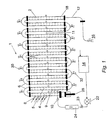
- a continuous polymerisation apparatus 1 comprises a reactor vessel 2 consisting of 14 parallel tubes 3 of 40 mm diameter.
- the reactor vessel is of much narrower diameter than known polymerisation apparatus.
- Adjacent tubes 3 are connected by U-bends 5 to form a continuous serpentine vessel 2 of total length of approximately 25,000 mm. This configuration of reactor vessel 2 provides economic use of space.
- This vessel 2 has a plurality of entry ports 8 in the first 4 and second 5 tubes of the vessel 2.
- the entry ports 8 in the first tube 4 are for the purpose of introducing the process components for the required reaction - such as monomers, surfactants and/or colloids - together with an initiator, to the reactor vessel 2 .
- the entry ports 9 in the second tube 5 are for the purpose of introducing a second initiator, should one be required for a particular reaction.
- Each of the following tubes 3 has at least one port 11 for sampling, and/or for measurement of pH and/or temperature.
- the vessel 2 has an inlet in the form of a non-return valve 10 at a first end and an outlet 12 at a second end, selectively connectable to a recycle tank 14 or a drain or product tank 16.
- the vessel 2 has further outlets at various positions along the vessel 2 which are normally closed but which, depending on the reaction time required, may be used to remove the contents of the vessel before they reach the far end of the vessel 2, effectively shortening the length of the vessel 2.
- the vessel contains approximately three hundred stainless steel annular baffles 18.
- Each baffle 18 has a free area ratio of 21%, and the baffles 18 are equally spaced apart along the length of the vessel (including the U-bends 6) with a distance of 1.8 x tube diameter (D) between adjacent baffles 18 (ie with a baffle spacing of 72 mm).
- the baffles 18 are supported by two 2 mm diameter stainless steel rods 20 welded therebetween.
- the baffles 18 and rods 20 are smooth to discourage solid deposits.
- the recycle tank 14 stores the reaction medium for the process (eg water or oil), and is situated above the level of the vessel 2.
- the tank 14 is in communication with the inlet 12.
- the apparatus 1 further comprises a stainless steel pump 22, a stainless steel rotameter (TM) 24 to measure flow rate, and a valve 23 to control flow rate.
- the pump 22 propels the reaction medium through the reactor vessel 2 to the outlet 12 at a selected flow rate.
- the outlet 12 is in communication with the recycle tank 14 which in turn is in communication with the inlet 10 to permit recycling of the medium through the reactor vessel 2.
- the outlet 12 is diverted to lead to the drain or product tank 16 to which the contents of the reactor vessel 2 are discharged.
- the apparatus further includes a port 26 for the continuous introduction of nitrogen to the vessel 2 via a rotameter (TM) 27.
- Nitrogen is required to purge the medium of oxygen both prior to and during a reaction.
- the apparatus 1 includes oscillation means in the form of stainless steel bellows 28, the operation of which oscillates the medium as it passes along the vessel 2.
- the entry ports 8 in the first tube 4 are positioned at sufficient distance from the bellows 28 to prevent any deposition on the surface of the bellows 28.
- the bellows 28 are driven by a motor of controllable speed.
- the frequency of oscillation is controlled by altering the speed of the motor. Frequencies of 0 to 10 Hz can be obtained.
- the preferred range of operation is 0 to 4 Hz.
- the apparatus 1 includes temperature control means in the form of a water jacket (not shown). This jacket surrounds the reactor vessel 2 and is used to vary the temperature of the vessel 2. There are a number of ports 11 along the length of the vessel 2 at which the temperature can be measured.
- the bellows 28 are situated sufficiently distant from the inlet 10 and thus the medium that, dependent on the reaction, the bellows 28 might not require cooling.
- the configuration of the bellows 28 prevents seepage of the medium from the vessel 2.
- the bellows 28 are connected to a motor via a flying wheel having a connecting pin. Control of the amplitude of oscillation of the medium by the bellows 28 is achieved by adjusting the off-centre position of the connecting pin. Oscillating amplitudes of 0 to 20 mm can be obtained.
- Each U-bend 6 includes a bleeding valve for releasing air 30 or for drainage 32.
- the apparatus 1 may be horizontal or vertical.
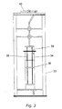
- the apparatus 1 includes a separate premixer in the form of a batch reactor 33.
- This batch reactor 33 has a reactor vessel in the form of a vertical tube 34.
- the reactor vessel 34 has an inlet 35 and contains a number of identical annular baffles 36.
- the baffles 36 are equally spaced and linked by two 2 mm diameter rods 38 to form a baffle set.
- the baffle set is connected to a top disc where it joins a bearing and is connected via a flying wheel to a motor drive 40 provided with a speed control.
- the flying wheel has an adjustable connecting pin.
- Oscillation of the baffle set is controllable by the motor drive.
- the frequency of oscillation of the baffle set is controllable by the speed control of the motor drive.
- the amplitude of oscillation of the baffle set is controllable by adjustment of the off-centre position of the connecting pin controls.
- This batch reactor 33 can be described as a batch oscillatory baffled reactor.
- This apparatus 1 is suitable for use in a method of polymerisation.
- the reactor vessel 2 is first washed using methyl-ethyl-ketone to remove any oil deposits. The washing process is repeated at least three or four times, and then deionised water is used to rinse the reactor vessel 2 throughout. An inert atmosphere is require for both the washing and polymerisation process, and a continuous flow of nitrogen is applied to the nitrogen inlet 26 to purge the reactor vessel 2.
- a pre-prepared aqueous medium is pumped from the recycle tank 14 through the reactor vessel 2.
- the aqueous medium usually consists of a protective colloid, two surfactants and deionised water.
- the bellows 28 are operated to oscillate the medium at a selected oscillation amplitude and a selected oscillation frequency.
- the rate of the flow is monitored by the rotameter (TM) 24.
- TM rotameter
- the monomer to be polymerised is supplied to the batch oscillatory reactor 33 for premixing with an initiator. Ammonia solution is also added to adjust pH value.
- the baffles 36 in the reactor vessel 34 are oscillated vertically , thereby generating eddies which mix the two uniformly.
- the fluid based mixture of monomer and initiator is pumped into the reactor vessel 2 via one of the ports 8, 9 therein at a controlled rate via a stainless steel pump 42 and rotameter 44.
- the entry port 8 selected depends on the mixing intensity required.
- the monomer and initiator are introduced simultaneously, either premixed, or at separate ports 8.
- a mixture of monomer and a first initiator is introduced at a port 8 in the first tube 4 of the vessel 2 to an oil phase typically consisting of isopart and a stabiliser and, after a period of between 3 and 5 minutes, a second initiator is then introduced at the port 9 at the point in the vessel 2 which has been reached by the admixture of monomer and first initiator after this time.
- the point in the vessel 2 reached by the mixture after this time depends upon the speed of flow as required, and the second initiator is introduced at an appropriate port 9 which can be in the second tube 5 of the vessel 2.
- the time when the mixture is fed is noted and, depending on the type of polymerisation process, the medium is recycled through the reactor vessel 2 for between 50 minutes and 2.5 hours. Polymerisation takes place in the reactor vessel 2 over this period of time.
- the fluid is mixed by the eddies generated as it flows through the stationary baffles 18.
- the eddies provide radial and axial motions in the fluid causing thorough and uniform mixing.
- the output is diverted to the drain or product tank 16 from which the content of the reactor vessel 2 is discharged.
- the polymer particles are then washed and filtered, and dried in an oven.
- Polymerisation by this method also offers both significantly greater process control than known processes, and accurate reproducibility.
- the droplet sizes obtained from a sample taken at an early stage of the process allows accurate prediction of the particle sizes of polymers ultimately produced.
- Uniform mixing coupled with a small steady flow component to obtain a long residence time in the reactor vessel, allows the polymerisation process to be operated in a continuous manner, and avoids the effect of the concentration gradient generated during the addition of monomer in batch operations on polymer particle size.
- This apparatus and method is used to produce polyacrylamide, polymethylmethacrylate, polystyrene or similar polymers.
- the method and apparatus is equally applicable to phase separated synthesis of a wide range of particulate materials including pharmaceutical, inorganic and organic crystals and particles, flocs, dyes, pigments and organic intermediates.
- the method and apparatus can be used for bead polymerisation, particle flocculation, crystallisation or fermentation.
- the reactor 33 of the apparatus 1 is also adaptable for the synthesis of polymethylmethacrylate, polystyrene and polyacrylamide in a batch process.
- polymers made in the batch reactor 33 have less than 1% of fine particles, (ie less than 1% unusable product), and Gaussian particle size distribution.
- a batch reactor 33 is suitable also for phase separated synthesis in a large scale.
- the reactor vessel 34 can be of between 0.1 to 5m in diameter.
Landscapes
- Chemical & Material Sciences (AREA)
- Organic Chemistry (AREA)
- Chemical Kinetics & Catalysis (AREA)
- Physical Or Chemical Processes And Apparatus (AREA)
- Polymerisation Methods In General (AREA)
- Organic Low-Molecular-Weight Compounds And Preparation Thereof (AREA)
Abstract
Description
The configuration of the
Claims (14)
- An apparatus (1) for polymerisation comprising:characterised in that said apparatus (1) is adapted for phase separated synthesis of particulates in a continuous manner, and in that said reactor vessel (2) comprises anti-fouling means (26,27).a reactor vessel (2);supply means (14) to supply a substantially continuous feed of an aqueous medium through the reactor vessel (2); andoscillation means (28) to oscillate liquid within the reactor vessel (2),said reactor vessel (2) comprising:an inlet (10) in communication with said supply means (14);an outlet (12) adaptable for communication with said supply means (14);a plurality of stationary baffles (18); andat least one port (8) for the introduction of process components and/or initiators;
- An apparatus (1) as claimed in Claim 1 wherein said reactor vessel comprises a plurality of ports (8,9) for the introduction of process components and/or initiators.
- An apparatus as claimed in any preceding claim wherein said reactor vessel (2) comprises a plurality of substantially parallel tubular sections (3) connected in series.
- An apparatus as claimed in any preceding claim wherein said oscillation means (28) comprises a chamber and a diaphragm.
- An apparatus as claimed in any preceding claim wherein said baffles (18) are annular.
- An apparatus as claimed in any preceding claim comprising temperature control means to vary the temperature of the reactor vessel (2).
- An apparatus as claimed in any preceding claim wherein said anti-fouling means comprises means (26,27) to introduce nitrogen to said reactor vessel (2) during operation of said supply means (14).
- An apparatus (1) as claimed in any preceding claim further comprising premixing means (33) to mix a process component and an initiator or initiators prior to their introduction to the reactor vessel (2).
- An apparatus (1) as claimed in Claim 8 wherein said premixing means (33) comprises a reactor vessel (34) comprising a plurality of baffles (36); and drive means to oscillate said baffles (36) to mix the process component and the initiator or initiators.
- An apparatus (1) as claimed in any preceding claim wherein said supply means comprises a reservoir (14) positioned above the level of the reactor vessel (2).
- A method of polymerisation comprising the steps of:characterised in that said method comprises the step of introducing an inert gas to the medium to purge the medium; and in that said method is controllable for the phase separated synthesis of particulates of specified size in a continuous manner.feeding an aqueous medium substantially continuously through a reactor vessel (2) comprising a plurality of stationary baffles (18);supplying a fluid containing at least one process component and an initiator or initiators to the vessel (2); andoscillating the liquid within the reactor vessel (2);
- A method as claimed in Claim 11 including the step of premixing a process component or process components with an initiator prior to their supply to the reactor vessel (2).
- A method of polymerisation in a continuous manner comprising the steps of:feeding an aqueous medium substantially continuously through a reactor vessel (2) comprising a plurality of stationary baffles (18);supplying a fluid containing at least one process component and an initiator or initiators to the reactor vessel (2); andoscillating the fluid in the reactor vessel (2) to produce particulates of specified size.
- A method as claimed in Claim 13 including the step of premixing a process component or process components with an initiator prior to their supply to the reactor vessel (2).
Applications Claiming Priority (5)
| Application Number | Priority Date | Filing Date | Title |
|---|---|---|---|
| GB9808969 | 1998-04-28 | ||
| GBGB9808969.1A GB9808969D0 (en) | 1998-04-28 | 1998-04-28 | Polymerisation method using a continuous oscillatory baffled reactor |
| GBGB9809230.7A GB9809230D0 (en) | 1998-04-30 | 1998-04-30 | Crystallisation method using batch oscillatory baffled reactor |
| GB9809230 | 1998-04-30 | ||
| PCT/GB1999/001323 WO1999055457A1 (en) | 1998-04-28 | 1999-04-28 | Method and apparatus for phase separated synthesis |
Publications (2)
| Publication Number | Publication Date |
|---|---|
| EP1076597A1 EP1076597A1 (en) | 2001-02-21 |
| EP1076597B1 true EP1076597B1 (en) | 2002-06-26 |
Family
ID=26313544
Family Applications (1)
| Application Number | Title | Priority Date | Filing Date |
|---|---|---|---|
| EP99919399A Expired - Lifetime EP1076597B1 (en) | 1998-04-28 | 1999-04-28 | Method and apparatus for phase separated synthesis |
Country Status (6)
| Country | Link |
|---|---|
| US (1) | US6429268B1 (en) |
| EP (1) | EP1076597B1 (en) |
| AT (1) | ATE219701T1 (en) |
| AU (1) | AU3720099A (en) |
| DE (1) | DE69901954D1 (en) |
| WO (1) | WO1999055457A1 (en) |
Cited By (2)
| Publication number | Priority date | Publication date | Assignee | Title |
|---|---|---|---|---|
| CN107108794A (en) * | 2014-12-19 | 2017-08-29 | 可泰克斯公司 | The method that anionic polymer is continuously prepared using free radical |
| US10345266B2 (en) | 2013-06-19 | 2019-07-09 | Indepth Inspection Technologies Inc. | Ultrasonic NDT inspection system |
Families Citing this family (33)
| Publication number | Priority date | Publication date | Assignee | Title |
|---|---|---|---|---|
| AUPR221600A0 (en) * | 2000-12-20 | 2001-01-25 | Austpac Resources Nl | Production of synthetic rutile by continuous leaching |
| DE10138828A1 (en) * | 2001-08-14 | 2003-03-06 | Bruno Berger | Homogeneous or heterogeneous chemical reactor comprises straight or bent slanted tubes arranged at an angle from the horizontal with openings which can be opened and closed for chemical materials with larger specific weight |
| EP1317954A1 (en) * | 2001-12-07 | 2003-06-11 | Avantium International B.V. | Batch reaction system |
| PL1711256T3 (en) * | 2004-01-06 | 2010-07-30 | Saudi Basic Ind Corp | Tubular polymerisation reactor for the preparation of polyethylene |
| US6969491B1 (en) | 2004-09-01 | 2005-11-29 | 3M Innovative Properties Company | Stirred tube reactor and method of using the same |
| US20100216631A1 (en) * | 2005-06-23 | 2010-08-26 | Ni Xiong-Wei | Method and apparatus for fluid-liquid reactions |
| GB0523245D0 (en) * | 2005-11-15 | 2005-12-21 | Nitech Solutions Ltd | Improved apparatus and method for applying oscillatory motion |
| NO20055456L (en) * | 2005-11-17 | 2007-05-18 | Fluens Synthesis As | Continuous flow reactor |
| GB0523707D0 (en) * | 2005-11-22 | 2005-12-28 | Nitech Solutions Ltd | Improved apparatus and method for temperature controlled processes |
| GB0604199D0 (en) * | 2006-03-02 | 2006-04-12 | Nitech Solutions Ltd | Apparatus and method for applying oscillatory motion |
| GB0614810D0 (en) * | 2006-07-25 | 2006-09-06 | Nitech Solutions Ltd | Improved apparatus and method for maintaining consistently mixed materials |
| GB0619835D0 (en) * | 2006-10-06 | 2006-11-15 | Univ Bath | Apparatus and process for use in three-phase catalytic reactions |
| GB0706908D0 (en) * | 2007-04-10 | 2007-05-16 | Nitech Solutions Ltd | Plug flow tubular mixing apparatus and method |
| GB0724179D0 (en) * | 2007-12-11 | 2008-01-23 | Ct For Process Innovation The | Fermentation process |
| US20090246074A1 (en) * | 2007-12-20 | 2009-10-01 | Purdue Research Foundation | System and method for sterilizing a processing line |
| GB0900080D0 (en) * | 2009-01-06 | 2009-02-11 | Prosonix Ltd | An apparatus and process for producing crystals |
| GB0919074D0 (en) | 2009-10-30 | 2009-12-16 | Cambridge Reactor Design Ltd | Crystallisation process and apparatus |
| IT1404150B1 (en) * | 2010-12-28 | 2013-11-15 | Polimeri Europa Spa | PROCEDURE FOR DEPRESSURIZATION OF FLUIDS AND DEVICE FOR THE PURPOSE |
| WO2012095176A1 (en) | 2011-01-13 | 2012-07-19 | Dsm Ip Assets B.V. | Oscillating flow minireactor |
| CN102151532B (en) * | 2011-04-22 | 2013-12-11 | 茂名重力石化机械制造有限公司 | Modular loop reactor |
| EP2847147B1 (en) | 2012-05-11 | 2017-07-12 | Saudi Arabian Oil Company | Ethylene oligomerization process |
| US9187388B2 (en) | 2012-09-05 | 2015-11-17 | Saudi Arabian Oil Company | Olefin hydration process using oscillatory baffled reactor |
| US10155707B2 (en) | 2012-09-05 | 2018-12-18 | Saudi Arabian Oil Company | Olefin hydration process using oscillatory baffled reactor |
| SG11201501712SA (en) * | 2012-10-08 | 2015-05-28 | Exxonmobil Upstream Res Co | Separating carbon dioxide from natural gas liquids |
| EP2719452A1 (en) * | 2012-10-12 | 2014-04-16 | Nederlandse Organisatie voor toegepast -natuurwetenschappelijk onderzoek TNO | Method and apparatus for physical or chemical processes |
| PT3057694T (en) | 2013-10-14 | 2019-07-30 | Univ Do Porto | Apparatus for mixing based on oscillatory flow reactors provided with smooth periodic constrictions |
| FR3042793B1 (en) | 2015-10-26 | 2019-12-27 | Arkema France | SYNTHESIS OF ORGANIC PEROXIDES USING AN AGITED OSCILLATORY FLOW REACTOR |
| BE1026312B1 (en) * | 2018-05-25 | 2019-12-23 | Ajinomoto Omnichem | Flow-through reactor and use thereof |
| GB201811402D0 (en) * | 2018-07-12 | 2018-08-29 | Alconbury Weston Ltd | Liquid process assembly |
| US11608450B2 (en) | 2019-08-01 | 2023-03-21 | Kraton Corporation | Process for a continuous reaction with feedstocks derived from Bio-Renewable resources |
| CN112050202B (en) * | 2020-09-03 | 2023-04-28 | 福大紫金氢能科技股份有限公司 | Tubular ammonia decomposition reactor |
| CN112090388B (en) * | 2020-09-07 | 2022-04-12 | 浙江大学 | Continuous flow reactor and application thereof in chemical reaction and synthesis |
| WO2024047407A1 (en) | 2022-09-01 | 2024-03-07 | Braskem S.A. | Continuous process for polymerization of vinyl chloride in a tubular reactor |
Family Cites Families (13)
| Publication number | Priority date | Publication date | Assignee | Title |
|---|---|---|---|---|
| GB1052971A (en) * | 1962-10-25 | |||
| US3674740A (en) * | 1969-04-22 | 1972-07-04 | Bayer Ag | Process of producing polycarbonate |
| CH542699A (en) | 1972-02-18 | 1973-10-15 | P Huerlimann Hans | Device for treating fabrics |
| US3855368A (en) | 1972-04-26 | 1974-12-17 | Ceskoslovenska Akademie Ved | Apparatus for bringing fluid phases into mutual contact |
| NL7700412A (en) * | 1977-01-15 | 1978-07-18 | Synres Internationaal Nv | CONTINUOUS PREPARATION OF POLYMERS IN THE MASS. |
| CA1146164A (en) | 1979-01-16 | 1983-05-10 | Giuseppe Cereghini | Opposed piston-cylinders operating a combined throttling-mixing and injection valve |
| CA1123578A (en) | 1979-11-20 | 1982-05-18 | Frank Souhrada | Process and apparatus for the prevention of solids deposits in a tubular reactor |
| CH649230A5 (en) | 1982-06-03 | 1985-05-15 | Sulzer Ag | REACTOR FOR THE CONTINUOUS IMPLEMENTATION OF POLYMERISATIONS IN HIGH VISCOSITY MEDIA. |
| GB8516344D0 (en) | 1985-06-28 | 1985-07-31 | Brunold C R | Mixing apparatus & processes |
| IT1230085B (en) * | 1989-05-24 | 1991-10-05 | Montedipe Spa | PROCESS FOR THE MASS AND CONTINUOUS PRODUCTION OF (CO) AROMATIC SHOCKPROOF VINYL POLYMERS. |
| DE69206759T2 (en) | 1991-10-26 | 1996-05-02 | Bp Chem Int Ltd | Process for the production of polyolefins |
| GB9313442D0 (en) | 1993-06-30 | 1993-08-11 | Bp Chem Int Ltd | Method of mixing heterogegeous systems |
| DE59504339D1 (en) | 1995-07-26 | 1999-01-07 | Sulzer Chemtech Ag | Method and device for carrying out a polymerization in a tubular reactor |
-
1999
- 1999-04-28 US US09/674,342 patent/US6429268B1/en not_active Expired - Lifetime
- 1999-04-28 AU AU37200/99A patent/AU3720099A/en not_active Abandoned
- 1999-04-28 AT AT99919399T patent/ATE219701T1/en not_active IP Right Cessation
- 1999-04-28 WO PCT/GB1999/001323 patent/WO1999055457A1/en not_active Ceased
- 1999-04-28 EP EP99919399A patent/EP1076597B1/en not_active Expired - Lifetime
- 1999-04-28 DE DE69901954T patent/DE69901954D1/en not_active Expired - Lifetime
Cited By (3)
| Publication number | Priority date | Publication date | Assignee | Title |
|---|---|---|---|---|
| US10345266B2 (en) | 2013-06-19 | 2019-07-09 | Indepth Inspection Technologies Inc. | Ultrasonic NDT inspection system |
| CN107108794A (en) * | 2014-12-19 | 2017-08-29 | 可泰克斯公司 | The method that anionic polymer is continuously prepared using free radical |
| CN107108794B (en) * | 2014-12-19 | 2020-06-05 | 可泰克斯公司 | Process for the continuous preparation of anionic polymers using free radicals |
Also Published As
| Publication number | Publication date |
|---|---|
| EP1076597A1 (en) | 2001-02-21 |
| US6429268B1 (en) | 2002-08-06 |
| DE69901954D1 (en) | 2002-08-01 |
| ATE219701T1 (en) | 2002-07-15 |
| AU3720099A (en) | 1999-11-16 |
| WO1999055457A1 (en) | 1999-11-04 |
Similar Documents
| Publication | Publication Date | Title |
|---|---|---|
| US6429268B1 (en) | Method and apparatus for phase separated synthesis | |
| JP5067767B2 (en) | Mixing apparatus and process | |
| US4666673A (en) | Apparatus for preparing large quantities of uniform size drops | |
| Ni et al. | Correlation of polymer particle size with droplet size in suspension polymerisation of methylmethacrylate in a batch oscillatory-baffled reactor | |
| CN105073843A (en) | Method of producing uniform, fine polymer beads by vibration jetting | |
| KR100526914B1 (en) | Method and device for continuous production of polymers | |
| KR101658375B1 (en) | Method and apparatus for preparing polymer beads of uniform particle size by suspension polymerization | |
| US5439991A (en) | Method of mixing heterogeneous systems | |
| CN102086240B (en) | Equipment and method for producing uniform particle ion exchange resin beads | |
| US20040048988A1 (en) | Tubular reactor qith coaxial cylinders and process using this reactor | |
| Leng et al. | Drop dispersion in suspension polymerization | |
| Ni et al. | Suspension polymerization of acrylamide in an oscillatory baffled reactor: from drops to particles | |
| JP4608701B2 (en) | Emulsion polymerization process and reactor for the process | |
| US3726648A (en) | Bulk polymerizer for vinyl chloride production | |
| KR20170011214A (en) | Continuous manufacturing system of nano-porous silica, and thereof method | |
| EP1110601A2 (en) | Modular reactor system allowing control of particle size during chemical precipitation | |
| KR970005478B1 (en) | Process for producing rubber-modified styrene resin, and resin composition | |
| SU1627243A1 (en) | Apparatus for polymerization | |
| JP2003026706A (en) | Continuous coagulation device and multi-stage polymerization device provided with this | |
| KR19980086878A (en) | Process vessel and process carried out in the vessel | |
| Lee et al. | The performance of the emulsion polymerization of styrene in a continuous loop tubular reactor | |
| RU2081700C1 (en) | Method and apparatus for programmed heating and cooling of biologic samples in liquid state | |
| US6716273B1 (en) | Method and device for eliminating oxygen contained in aqueous monomer solutions | |
| RU2158174C1 (en) | Plant for preparation of multi-components liquid phase mixtures | |
| BG67456B1 (en) | Polymerization installation with integrated combined absorption-diffusion and absorption-condensation unit and its application for polymer and copolymer preparation |
Legal Events
| Date | Code | Title | Description |
|---|---|---|---|
| PUAI | Public reference made under article 153(3) epc to a published international application that has entered the european phase |
Free format text: ORIGINAL CODE: 0009012 |
|
| 17P | Request for examination filed |
Effective date: 20001124 |
|
| AK | Designated contracting states |
Kind code of ref document: A1 Designated state(s): AT BE CH CY DE DK ES FI FR GB GR IE IT LI LU NL PT SE |
|
| 17Q | First examination report despatched |
Effective date: 20010308 |
|
| GRAG | Despatch of communication of intention to grant |
Free format text: ORIGINAL CODE: EPIDOS AGRA |
|
| GRAG | Despatch of communication of intention to grant |
Free format text: ORIGINAL CODE: EPIDOS AGRA |
|
| GRAH | Despatch of communication of intention to grant a patent |
Free format text: ORIGINAL CODE: EPIDOS IGRA |
|
| GRAH | Despatch of communication of intention to grant a patent |
Free format text: ORIGINAL CODE: EPIDOS IGRA |
|
| GRAA | (expected) grant |
Free format text: ORIGINAL CODE: 0009210 |
|
| AK | Designated contracting states |
Kind code of ref document: B1 Designated state(s): AT BE CH CY DE DK ES FI FR GB GR IE IT LI LU NL PT SE |
|
| PG25 | Lapsed in a contracting state [announced via postgrant information from national office to epo] |
Ref country code: LI Free format text: LAPSE BECAUSE OF FAILURE TO SUBMIT A TRANSLATION OF THE DESCRIPTION OR TO PAY THE FEE WITHIN THE PRESCRIBED TIME-LIMIT Effective date: 20020626 Ref country code: IT Free format text: LAPSE BECAUSE OF FAILURE TO SUBMIT A TRANSLATION OF THE DESCRIPTION OR TO PAY THE FEE WITHIN THE PRESCRIBED TIME-LIMIT;WARNING: LAPSES OF ITALIAN PATENTS WITH EFFECTIVE DATE BEFORE 2007 MAY HAVE OCCURRED AT ANY TIME BEFORE 2007. THE CORRECT EFFECTIVE DATE MAY BE DIFFERENT FROM THE ONE RECORDED. Effective date: 20020626 Ref country code: GR Free format text: LAPSE BECAUSE OF FAILURE TO SUBMIT A TRANSLATION OF THE DESCRIPTION OR TO PAY THE FEE WITHIN THE PRESCRIBED TIME-LIMIT Effective date: 20020626 Ref country code: FI Free format text: LAPSE BECAUSE OF FAILURE TO SUBMIT A TRANSLATION OF THE DESCRIPTION OR TO PAY THE FEE WITHIN THE PRESCRIBED TIME-LIMIT Effective date: 20020626 Ref country code: CH Free format text: LAPSE BECAUSE OF FAILURE TO SUBMIT A TRANSLATION OF THE DESCRIPTION OR TO PAY THE FEE WITHIN THE PRESCRIBED TIME-LIMIT Effective date: 20020626 Ref country code: BE Free format text: LAPSE BECAUSE OF FAILURE TO SUBMIT A TRANSLATION OF THE DESCRIPTION OR TO PAY THE FEE WITHIN THE PRESCRIBED TIME-LIMIT Effective date: 20020626 Ref country code: AT Free format text: LAPSE BECAUSE OF FAILURE TO SUBMIT A TRANSLATION OF THE DESCRIPTION OR TO PAY THE FEE WITHIN THE PRESCRIBED TIME-LIMIT Effective date: 20020626 |
|
| REF | Corresponds to: |
Ref document number: 219701 Country of ref document: AT Date of ref document: 20020715 Kind code of ref document: T |
|
| REG | Reference to a national code |
Ref country code: GB Ref legal event code: FG4D |
|
| REG | Reference to a national code |
Ref country code: CH Ref legal event code: EP |
|
| REG | Reference to a national code |
Ref country code: IE Ref legal event code: FG4D |
|
| REF | Corresponds to: |
Ref document number: 69901954 Country of ref document: DE Date of ref document: 20020801 |
|
| PG25 | Lapsed in a contracting state [announced via postgrant information from national office to epo] |
Ref country code: SE Free format text: LAPSE BECAUSE OF FAILURE TO SUBMIT A TRANSLATION OF THE DESCRIPTION OR TO PAY THE FEE WITHIN THE PRESCRIBED TIME-LIMIT Effective date: 20020926 Ref country code: PT Free format text: LAPSE BECAUSE OF FAILURE TO SUBMIT A TRANSLATION OF THE DESCRIPTION OR TO PAY THE FEE WITHIN THE PRESCRIBED TIME-LIMIT Effective date: 20020926 Ref country code: DK Free format text: LAPSE BECAUSE OF FAILURE TO SUBMIT A TRANSLATION OF THE DESCRIPTION OR TO PAY THE FEE WITHIN THE PRESCRIBED TIME-LIMIT Effective date: 20020926 |
|
| PG25 | Lapsed in a contracting state [announced via postgrant information from national office to epo] |
Ref country code: DE Free format text: LAPSE BECAUSE OF FAILURE TO SUBMIT A TRANSLATION OF THE DESCRIPTION OR TO PAY THE FEE WITHIN THE PRESCRIBED TIME-LIMIT Effective date: 20020927 |
|
| ET | Fr: translation filed | ||
| PG25 | Lapsed in a contracting state [announced via postgrant information from national office to epo] |
Ref country code: ES Free format text: LAPSE BECAUSE OF FAILURE TO SUBMIT A TRANSLATION OF THE DESCRIPTION OR TO PAY THE FEE WITHIN THE PRESCRIBED TIME-LIMIT Effective date: 20021220 |
|
| REG | Reference to a national code |
Ref country code: CH Ref legal event code: PL |
|
| PG25 | Lapsed in a contracting state [announced via postgrant information from national office to epo] |
Ref country code: LU Free format text: LAPSE BECAUSE OF NON-PAYMENT OF DUE FEES Effective date: 20030428 Ref country code: IE Free format text: LAPSE BECAUSE OF NON-PAYMENT OF DUE FEES Effective date: 20030428 Ref country code: CY Free format text: LAPSE BECAUSE OF FAILURE TO SUBMIT A TRANSLATION OF THE DESCRIPTION OR TO PAY THE FEE WITHIN THE PRESCRIBED TIME-LIMIT Effective date: 20030428 |
|
| PLBE | No opposition filed within time limit |
Free format text: ORIGINAL CODE: 0009261 |
|
| STAA | Information on the status of an ep patent application or granted ep patent |
Free format text: STATUS: NO OPPOSITION FILED WITHIN TIME LIMIT |
|
| 26N | No opposition filed |
Effective date: 20030327 |
|
| REG | Reference to a national code |
Ref country code: IE Ref legal event code: MM4A |
|
| NLS | Nl: assignments of ep-patents |
Owner name: NITECH SOLUTIONS LIMITED Effective date: 20070416 |
|
| REG | Reference to a national code |
Ref country code: FR Ref legal event code: TP |
|
| REG | Reference to a national code |
Ref country code: FR Ref legal event code: PLFP Year of fee payment: 18 |
|
| REG | Reference to a national code |
Ref country code: FR Ref legal event code: PLFP Year of fee payment: 19 |
|
| REG | Reference to a national code |
Ref country code: FR Ref legal event code: PLFP Year of fee payment: 20 |
|
| PGFP | Annual fee paid to national office [announced via postgrant information from national office to epo] |
Ref country code: NL Payment date: 20180417 Year of fee payment: 20 |
|
| PGFP | Annual fee paid to national office [announced via postgrant information from national office to epo] |
Ref country code: FR Payment date: 20180424 Year of fee payment: 20 |
|
| PGFP | Annual fee paid to national office [announced via postgrant information from national office to epo] |
Ref country code: GB Payment date: 20180410 Year of fee payment: 20 |
|
| REG | Reference to a national code |
Ref country code: NL Ref legal event code: MK Effective date: 20190427 |
|
| REG | Reference to a national code |
Ref country code: GB Ref legal event code: PE20 Expiry date: 20190427 |
|
| PG25 | Lapsed in a contracting state [announced via postgrant information from national office to epo] |
Ref country code: GB Free format text: LAPSE BECAUSE OF EXPIRATION OF PROTECTION Effective date: 20190427 |