EP1076581B1 - Medical electrical lead - Google Patents
Medical electrical lead Download PDFInfo
- Publication number
- EP1076581B1 EP1076581B1 EP99913904A EP99913904A EP1076581B1 EP 1076581 B1 EP1076581 B1 EP 1076581B1 EP 99913904 A EP99913904 A EP 99913904A EP 99913904 A EP99913904 A EP 99913904A EP 1076581 B1 EP1076581 B1 EP 1076581B1
- Authority
- EP
- European Patent Office
- Prior art keywords
- shaft
- seal
- helix
- lead
- proximal
- Prior art date
- Legal status (The legal status is an assumption and is not a legal conclusion. Google has not performed a legal analysis and makes no representation as to the accuracy of the status listed.)
- Expired - Lifetime
Links
Images


Classifications
-
- A—HUMAN NECESSITIES
- A61—MEDICAL OR VETERINARY SCIENCE; HYGIENE
- A61N—ELECTROTHERAPY; MAGNETOTHERAPY; RADIATION THERAPY; ULTRASOUND THERAPY
- A61N1/00—Electrotherapy; Circuits therefor
- A61N1/02—Details
- A61N1/04—Electrodes
- A61N1/05—Electrodes for implantation or insertion into the body, e.g. heart electrode
- A61N1/056—Transvascular endocardial electrode systems
- A61N1/057—Anchoring means; Means for fixing the head inside the heart
- A61N1/0573—Anchoring means; Means for fixing the head inside the heart chacterised by means penetrating the heart tissue, e.g. helix needle or hook
Definitions
- the present invention is directed toward medical electrical leads generally and more particularly directed towards medical leads employing advanceable, rotating fixation helixes to anchor the leads to body tissue.
- cardiac pacing leads need to be located stably adjacent tissue to be stimulated or monitored.
- One common mechanism for accomplishing this has been the use of a rotatable fixation helix, which exits the distal end of the lead and is screwed into body tissue.
- the helix itself may serve as an electrode or it may simply serve as an anchoring mechanism to locate an electrode mounted to the lead body adjacent body tissue.
- the fixation helix may be coupled to a conductor extending through the lead body and rotated by rotation of the conductor within the lead body.
- a lead is disclosed in U.S. Patent No. 4,106,512 issued to Bisping.
- the fixation helix may be rotated by means of a screwdriver tip stylet, or other removable rotation device, as disclosed in U.S. Patent No. 4,217,913 issued to Dutcher.
- Some mechanism is provided for sealing the distal end of the lead against fluid entry.
- One common mechanism is to provide a seal which engages the fixation helix directly, as disclosed in the above cited Bisping patent.
- An alternative mechanism, particularly useful in the circumstance in which the helix is mounted to a shaft, either rotated by means of the conductor or by means of a screwdriver stylet, is to operatively associate a seal with the helix shaft for preventing the ingress of body fluids, by mounting a washer shaped seal encircling the shaft.
- the seal may either rotate with the shaft, as disclosed in European Patent Application No. 0149431 issued to Borghi et al or the shaft may rotate relative to the seal as disclosed in U.S. Patent No.
- the helix shaft In the event that it is desired to mount a seal located fixedly within the electrode head, surrounding the helix shaft, as in the Doan patents and the Bens patents cited above, it is necessary to pass the helix shaft through the seal. Similarly, if one wishes to employ washer-shaped members on either side of the seal as in the Bens and Doan '708 patents, the helix shaft must either carry the washer shaped members or must pass through the central apertures in the washer shaped members. This generally is not a problem, except in the context of a shaft which rotates relative to the seal when it is desired that the helix shaft be constructed with enlarged radius shoulders, located on either side of the seal to define advancement and retraction stops. If washer-shaped retainers are to be used as in the Doan '708 patent, the helix shaft must be fabricated out of two separate pieces.
- the present invention provides a medical electrical lead, comprising:
- the helix shaft is provided with enlarged shoulders located proximal and distal to the central portion of the shaft which passes through the seal, which shoulders serve as advancement and retraction stops.
- the seal is placed around the shaft between the shoulders and is maintained properly located within the electrode head by means of two C-shaped retainers which engage the proximal and distal shoulders of the helix shaft to define positions of maximum advancement and retraction.
- the C-shaped retainers in conjunction with the enlarged shoulders on the shaft also provide a mechanism for determining the degree of advancement of the helix and shaft using a fluoroscope.
- the C-shaped retainers and the seal are placed around the helix shaft prior to the insertion of the helix shaft into the electrode head. By this mechanism, the helix shaft can be fabricated as a single piece part, simplifying manufacture of the lead.
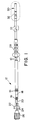
- Figure 1 is a plan view of a lead incorporating the present invention.
- Figure 2 is a cut-away view through the distal portion of the lead illustrated in Figure 1.
- Figure 3 is a perspective view of one of the C-shaped seal retainers employed in the lead of Figures 1 and 2.
- Figure 4 is a perspective view of the helix shaft of the lead of Figures 1 and 2, shown with the seal and two C-shaped seal retainers mounted thereto.
- FIG. 1 is a plan view of a cardiac pacing lead employing the present invention.
- the lead is provided with an elongated lead body 10 which takes the form of an extruded tube of biocompatible plastic such as silicone rubber or polyurethane.
- a connector assembly 12 which includes a connector pin 20 and a connector ring 18 which are coupled to coil conductors extending distally therefrom within lead body 10.
- Sealing rings 14 and 16 are provided to seal the connector assembly in the connector block in an associated implantable cardiac pacemaker and to seal between connector pin 20 and connector ring 18.
- Exiting the proximal end of the connector pin 20 is a stylet 24, shown exiting through removable stylet guide 22.
- Stylet knob 26 is provided to assist the physician in moving and turning stylet 24 relative to the lead body 10 in order to assist in placement of the lead at a desired location within a patient's heart.
- Suture sleeve 28 is provided to assist in anchoring the lead at the point of venous insertion.
- An electrode head 30 is located at the distal end of the lead, and carries an advanceable fixation helix as described generally above.
- a ring electrode 32 is mounted proximal to electrode head 30. Electrode 32 is electrically coupled to connector 18 and the advanceable fixation helix within electrode head 30 is electrically coupled to connector pin 20.
- Rotation of connector pin 20 relative to the connector assembly 12 causes corresponding rotation of the coiled conductor coupled thereto and advancement or retraction of the fixation helix within lead 30 in the fashion generally described in U.S. Patent No. 4,106,512 issued to Bisping et al.
- the lead of Figure 6 takes the form of a bipolar pacing lead
- the present invention may of course be embodied in other types of pacing leads, including unipolar leads and leads with additional electrodes and/or sensors.
- the invention is also useful in the context of implantable cardioversion and defibrillation leads and in any other circumstance in which it is desirable to affix a lead adjacent to body tissue to stimulate or sense electrical activity in the body, including nerve and muscle stimulation leads and the like.
- FIG 2 is a cut-away view through the distal portion of the lead of Figure 1.
- Lead body 10 in this view is seen to be an elongated extruded tube of biocompatible plastic, which surrounds two coaxially arranged coiled conductors 62 and 68, each of which takes the form of multifilar coils of biocompatible metal such as MP35N alloy, drawn brazed strand wire, or other conductors conventionally employed in implantable stimulation leads.
- Separating conductors 62 and 68 is an inner insulative sheath 60 which also takes the form of an extruded tube of biocompatible plastic such as polyurethane or silicone rubber.
- Ring electrode 32 is fabricated of a biocompatible metal such as stainless steel or platinum/iridium alloy and is coupled to coiled conductor 68 by means of a weld adjacent the circumferential flange 66 located on the proximal portion of the ring electrode.
- a cross bore 69 through a ring electrode 32 is provided to allow for backfilling to bond the distal portion of lead body 10 to the inner insulative sheath 60 and thereby providing a mechanical interlock.
- Electrode head assembly 30 includes a main head member 38 which takes the form of a generally tubular molding of rigid, biocompatible plastic, such as a polyurethane, a proximal head member 58 which also is a generally tubular molding of biocompatible plastic and a distal head member 36, molded of biocompatible silicone rubber, polyurethane or other biocompatible plastic, containing a steroid, for example a form of dexamethasone which will elute from the plastic.
- an advanceable fixation helix 34 which is fabricated of a biocompatible metal such as platinum/iridium alloy and serves as the pacing electrode.
- Helix 34 engages inward projection 40 in a fashion such that upon rotation of helix 34, it is either screwed into or out of the distal opening in distal head member 36.
- the proximal end of fixation helix 34 is coupled to the distal portion 50 helix shaft 42.
- the proximal end 64 of shaft 42 is in turn coupled to coiled conductor 62, such that upon rotation of coil conductor 62, fixation helix 34 rotates relative to protrusion 40, causing it to be screwed into out of electrode head assembly.
- a resilient seal 56 which may be molded of a biocompatible plastic such as silicone rubber or polyurethane.
- the internal bore of seal 56, through which helix shaft 42 passes is essentially cylindrical.
- C-shaped retaining members 52 and 54 Located on either side of seal 56 are C-shaped retaining members 52 and 54 visible in cross-section. These retaining members are preferably fabricated of a biocompatible radiopaque metal such as platinum or platinum-iridium alloy and serve both to locate seal 56 in the electrode head and as proximal and distal stops, limiting proximal and distal movement of helix shaft 42.
- the distal portion of the outer surface of the seal 56 is conically tapered, which allows a wider range of tolerances for the components of the electrode head assembly and simplifies assembly when the helix shaft 42, seal 56 and seal retainers 52 and 54 are slid distally into head member 38.
- helix 34 is fully retracted into the electrode head assembly, with the enlarged circumferential distal shoulder 48 of the helix shaft abutting C-shaped seal retainer 54.
- the enlarged proximal circumferential shoulder 44 of shaft 42 abuts C-shaped seal retainer 52.
- C-shaped seal retainers 52 also serve as radiopaque indicators, having fixed locations relative to the electrode head assembly 30, which allows the physician to determine the relative degree of advancement of helix 34 by comparing the relative locations of the C-shaped retainers 52 and 54 and helix shaft 42.
- C-shaped seal retainers 52 and 54 in conjunction with a resilient seal 56 allows the seal and retainers to first be located around the central shaft portion 46 and assembly thereafter to be advanced into the main electrode head member 38.
- the proximal electrode head member 58 can then be inserted into the proximal end of the main electrode head member 38 and bonded thereto by means of adhesive or otherwise, retaining the assembly of helix shaft 42, retainers 52 and 54 and seal 56 within the electrode head assembly 30.
- Figure 3 is a perspective viewing of one of the two retainers 52, illustrating its C-shaped configuration.
- Figure 4 is a perspective view of the helix shaft 42, seen generally from its proximal end, with seal 56 and C-shaped retainers 52 and 54 located thereon, prior to insertion of the assembly into the electrode head. It should be understood that prior to insertion of this assembly into the electrode head, the fixation helix would be attached to the distal portion 50 of shaft 42 and the coiled conductor 62 would be attached to the proximal end 64 of the helix shaft.
- the resilient seal is seal expanded, slipped over one of the two shoulders 44 and 48 on the helix shaft and placed around the central shaft portion 46 of the helix shaft 42.
- C-shaped retainers are shown located facing oppositely with respect to one another, although this is not necessary for the assembly to function properly and are mounted on either side of the seal, along the central shaft portion 46.
- Use of the C-shaped retainers in conjunction with the split seal allows shaft 42 to be fabricated as a single piece part, simplifying manufacture and assembly of the lead.
Landscapes
- Health & Medical Sciences (AREA)
- Cardiology (AREA)
- Heart & Thoracic Surgery (AREA)
- Vascular Medicine (AREA)
- Engineering & Computer Science (AREA)
- Biomedical Technology (AREA)
- Nuclear Medicine, Radiotherapy & Molecular Imaging (AREA)
- Radiology & Medical Imaging (AREA)
- Life Sciences & Earth Sciences (AREA)
- Animal Behavior & Ethology (AREA)
- General Health & Medical Sciences (AREA)
- Public Health (AREA)
- Veterinary Medicine (AREA)
- Electrotherapy Devices (AREA)
Description
C-shaped retainers are shown located facing oppositely with respect to one another, although this is not necessary for the assembly to function properly and are mounted on either side of the seal, along the
Claims (4)
- A medical electrical lead, comprising:an elongate lead body (10) having proximal and distal ends and carrying an elongate conductor (62, 68) therein;an electrode head member (36, 38) having an internal lumen, mounted to a proximal portion of the lead body;a shaft (42), having proximal (64) and distal (50) ends, rotatably mounted in the head member;a fixation helix (34), mounted to the distal end of the shaft;a resilient seal (56), mounted in the lumen of the electrode head member, encircling the shaft; andmembers (52, 54) mounted in the lumen of the electrode head member proximal and distal to the seal, and wherein the shaft is provided with circumferential shoulders (44) proximal and distal to the members (52, 54), characterised in that said members (52, 54) are C-shaped members.
- A lead according to claim 1, wherein the conductor is rotatably mounted in the lead body (10) and is coupled to the helix shaft (42).
- A lead according to any preceeding claim wherein the C-shaped members (52, 54) are fabricated of radiopaque material.
- A lead according to any preceding claim wherein the outer surface of the seal (56) is tapered.
Applications Claiming Priority (3)
| Application Number | Priority Date | Filing Date | Title |
|---|---|---|---|
| US09/078,977 US5948015A (en) | 1998-05-14 | 1998-05-14 | Medical electrical lead |
| US78977 | 1998-05-14 | ||
| PCT/US1999/005702 WO1999058189A1 (en) | 1998-05-14 | 1999-03-15 | Medical electrical lead |
Publications (2)
| Publication Number | Publication Date |
|---|---|
| EP1076581A1 EP1076581A1 (en) | 2001-02-21 |
| EP1076581B1 true EP1076581B1 (en) | 2004-10-27 |
Family
ID=22147355
Family Applications (1)
| Application Number | Title | Priority Date | Filing Date |
|---|---|---|---|
| EP99913904A Expired - Lifetime EP1076581B1 (en) | 1998-05-14 | 1999-03-15 | Medical electrical lead |
Country Status (6)
| Country | Link |
|---|---|
| US (1) | US5948015A (en) |
| EP (1) | EP1076581B1 (en) |
| JP (1) | JP2002514476A (en) |
| CA (1) | CA2331280C (en) |
| DE (1) | DE69921469T2 (en) |
| WO (1) | WO1999058189A1 (en) |
Families Citing this family (23)
| Publication number | Priority date | Publication date | Assignee | Title |
|---|---|---|---|---|
| US6501992B1 (en) * | 2000-10-17 | 2002-12-31 | Medtronic, Inc. | Radiopaque marking of lead electrode zone in a continuous conductor construction |
| US6931285B2 (en) | 2001-04-17 | 2005-08-16 | Medtronic, Inc. | Drive shaft seal for a medical electrical lead |
| US20030065374A1 (en) * | 2001-10-01 | 2003-04-03 | Medtronic, Inc. | Active fixation lead with helix extension indicator |
| US7091412B2 (en) | 2002-03-04 | 2006-08-15 | Nanoset, Llc | Magnetically shielded assembly |
| US20050247472A1 (en) * | 2002-01-22 | 2005-11-10 | Helfer Jeffrey L | Magnetically shielded conductor |
| US7162302B2 (en) | 2002-03-04 | 2007-01-09 | Nanoset Llc | Magnetically shielded assembly |
| US20040088033A1 (en) * | 2002-10-31 | 2004-05-06 | Smits Karel F.A.A. | Implantable medical lead designs |
| US8010207B2 (en) | 2002-10-31 | 2011-08-30 | Medtronic, Inc. | Implantable medical lead designs |
| US7945337B2 (en) * | 2003-08-27 | 2011-05-17 | Medtronic, Inc. | High impedance and low polarization electrode |
| US20050070984A1 (en) * | 2003-09-29 | 2005-03-31 | Sundberg Gregory L. | Extendable and retractable lead with an active fixation assembly |
| US7190993B2 (en) * | 2003-11-04 | 2007-03-13 | Medtronic, Inc. | Implantable medical device having optical fiber for sensing electrical activity |
| US20080103572A1 (en) | 2006-10-31 | 2008-05-01 | Medtronic, Inc. | Implantable medical lead with threaded fixation |
| US20080154326A1 (en) * | 2006-12-21 | 2008-06-26 | Clyne Christopher A | Method and apparatus for providing a radiopaque anchoring sleeve |
| US8396539B2 (en) | 2007-02-16 | 2013-03-12 | Medtronic, Inc. | Implantable medical device having optical fiber for sensing electrical activity |
| WO2008153451A1 (en) * | 2007-06-13 | 2008-12-18 | St. Jude Medical Ab | Medical implantable lead and method for mounting the same |
| WO2009102972A1 (en) * | 2008-02-15 | 2009-08-20 | Cardiac Pacemakers, Inc. | Modular, zone-specific medical electrical lead design |
| EP2379164B1 (en) | 2008-12-19 | 2016-05-11 | St. Jude Medical AB | Implantable medical lead with a movable radiopaque marker |
| WO2019090256A1 (en) | 2017-11-06 | 2019-05-09 | Pacesetter, Inc. | Biostimulator having fixation element |
| US11577086B2 (en) | 2018-08-20 | 2023-02-14 | Pacesetter, Inc. | Fixation mechanisms for a leadless cardiac biostimulator |
| USD894396S1 (en) | 2019-03-08 | 2020-08-25 | Pacesetter, Inc. | Leadless biostimulator attachment feature |
| US11541243B2 (en) | 2019-03-15 | 2023-01-03 | Pacesetter, Inc. | Biostimulator having coaxial fixation elements |
| US12654003B2 (en) * | 2020-07-30 | 2026-06-16 | Medtronic, Inc. | Electrode placement apparatus and methods |
| EP4368237A1 (en) * | 2022-11-08 | 2024-05-15 | BIOTRONIK SE & Co. KG | Implantable lead and manufacturing method therefor |
Family Cites Families (11)
| Publication number | Priority date | Publication date | Assignee | Title |
|---|---|---|---|---|
| US4106512A (en) * | 1976-12-16 | 1978-08-15 | Medtronic, Inc. | Transvenously implantable lead |
| US4217913A (en) * | 1977-10-10 | 1980-08-19 | Medtronic, Inc. | Body-implantable lead with protected, extendable tissue securing means |
| DE3038019C2 (en) | 1980-10-08 | 1984-03-15 | Gema Bauelemente AG, 9015 St. Gallen | Grid ceiling |
| US4624266A (en) * | 1983-12-19 | 1986-11-25 | Daig Corporation | Introducer tool for screw-in lead |
| US4624265A (en) * | 1985-07-24 | 1986-11-25 | Ge. Sv. In. S.R.L. | Electro-catheter used in physiological cardiac stimulation simulative of the auriculo-ventricular sequence, featuring active engagement of the cardiac muscle |
| FR2671010B1 (en) * | 1990-12-27 | 1993-07-09 | Ela Medical Sa | ENDOCARDIAC PROBE PROVIDED WITH AN ACTIVE FIXING MEMBER |
| US5447533A (en) * | 1992-09-03 | 1995-09-05 | Pacesetter, Inc. | Implantable stimulation lead having an advanceable therapeutic drug delivery system |
| AU5215493A (en) * | 1992-12-04 | 1994-06-16 | Pacesetter Ab | Rotatable pin, screw-in pacing and sensing lead having teflon-coated conductor coil |
| US5300108A (en) * | 1993-01-05 | 1994-04-05 | Telectronics Pacing Systems, Inc. | Active fixation lead with a dual-pitch, free spinning compound screw |
| US5456708A (en) * | 1993-10-28 | 1995-10-10 | Pacesetter, Inc. | Rotatable pin, screw-in pacing and sensing lead having improved tip and fluidic seal |
| US5851226A (en) * | 1996-10-22 | 1998-12-22 | Medtronic, Inc. | Temporary transvenous endocardial lead |
-
1998
- 1998-05-14 US US09/078,977 patent/US5948015A/en not_active Expired - Lifetime
-
1999
- 1999-03-15 JP JP2000548037A patent/JP2002514476A/en active Pending
- 1999-03-15 CA CA002331280A patent/CA2331280C/en not_active Expired - Fee Related
- 1999-03-15 WO PCT/US1999/005702 patent/WO1999058189A1/en not_active Ceased
- 1999-03-15 DE DE69921469T patent/DE69921469T2/en not_active Expired - Lifetime
- 1999-03-15 EP EP99913904A patent/EP1076581B1/en not_active Expired - Lifetime
Also Published As
| Publication number | Publication date |
|---|---|
| DE69921469D1 (en) | 2004-12-02 |
| EP1076581A1 (en) | 2001-02-21 |
| WO1999058189A1 (en) | 1999-11-18 |
| US5948015A (en) | 1999-09-07 |
| CA2331280A1 (en) | 1999-11-18 |
| JP2002514476A (en) | 2002-05-21 |
| CA2331280C (en) | 2003-12-09 |
| DE69921469T2 (en) | 2005-10-13 |
Similar Documents
| Publication | Publication Date | Title |
|---|---|---|
| US5948015A (en) | Medical electrical lead | |
| EP0709111B1 (en) | Medical electrical lead system having a torque transfer stylet | |
| US6192280B1 (en) | Guidewire placed implantable lead with tip seal | |
| US5002067A (en) | Medical electrical lead employing improved penetrating electrode | |
| US6478777B1 (en) | Introducer system for medical electrical lead | |
| EP0422363B1 (en) | Screw-in drug eluting medical lead for implantation | |
| EP0129875B1 (en) | Body implantable lead and method for imparting a curve to such a lead | |
| US5342414A (en) | Transvenous defibrillation lead | |
| CA2194744C (en) | Active fixation medical electrical lead having improved turning tool | |
| US6038463A (en) | Medical electrical lead | |
| US8219213B2 (en) | Active fixation cardiac vein medical lead | |
| US20020188338A1 (en) | Drive shaft seal for a medical electrical lead | |
| US20030065374A1 (en) | Active fixation lead with helix extension indicator | |
| CA2564198A1 (en) | Novel lead body assemblies | |
| US6016436A (en) | Medical electrical lead | |
| US8478429B2 (en) | Extendable/retractable fixation lead with distal travelling seal and related devices | |
| US9227054B2 (en) | Active fixation leads and method of assembly | |
| WO2023002001A1 (en) | Tool for continuous insertion-depth monitoring for implantable lead | |
| EP1017445B1 (en) | Medical electrical lead |
Legal Events
| Date | Code | Title | Description |
|---|---|---|---|
| PUAI | Public reference made under article 153(3) epc to a published international application that has entered the european phase |
Free format text: ORIGINAL CODE: 0009012 |
|
| 17P | Request for examination filed |
Effective date: 20001212 |
|
| AK | Designated contracting states |
Kind code of ref document: A1 Designated state(s): CH DE FR LI NL SE |
|
| 17Q | First examination report despatched |
Effective date: 20040219 |
|
| GRAP | Despatch of communication of intention to grant a patent |
Free format text: ORIGINAL CODE: EPIDOSNIGR1 |
|
| RAP1 | Party data changed (applicant data changed or rights of an application transferred) |
Owner name: MEDTRONIC INC. |
|
| RAP1 | Party data changed (applicant data changed or rights of an application transferred) |
Owner name: MEDTRONIC, INC. |
|
| GRAS | Grant fee paid |
Free format text: ORIGINAL CODE: EPIDOSNIGR3 |
|
| GRAA | (expected) grant |
Free format text: ORIGINAL CODE: 0009210 |
|
| AK | Designated contracting states |
Kind code of ref document: B1 Designated state(s): CH DE FR LI NL SE |
|
| PG25 | Lapsed in a contracting state [announced via postgrant information from national office to epo] |
Ref country code: LI Free format text: LAPSE BECAUSE OF FAILURE TO SUBMIT A TRANSLATION OF THE DESCRIPTION OR TO PAY THE FEE WITHIN THE PRESCRIBED TIME-LIMIT Effective date: 20041027 Ref country code: CH Free format text: LAPSE BECAUSE OF FAILURE TO SUBMIT A TRANSLATION OF THE DESCRIPTION OR TO PAY THE FEE WITHIN THE PRESCRIBED TIME-LIMIT Effective date: 20041027 |
|
| REG | Reference to a national code |
Ref country code: CH Ref legal event code: EP |
|
| REF | Corresponds to: |
Ref document number: 69921469 Country of ref document: DE Date of ref document: 20041202 Kind code of ref document: P |
|
| PG25 | Lapsed in a contracting state [announced via postgrant information from national office to epo] |
Ref country code: SE Free format text: LAPSE BECAUSE OF FAILURE TO SUBMIT A TRANSLATION OF THE DESCRIPTION OR TO PAY THE FEE WITHIN THE PRESCRIBED TIME-LIMIT Effective date: 20050127 |
|
| REG | Reference to a national code |
Ref country code: CH Ref legal event code: PL |
|
| ET | Fr: translation filed | ||
| PLBE | No opposition filed within time limit |
Free format text: ORIGINAL CODE: 0009261 |
|
| STAA | Information on the status of an ep patent application or granted ep patent |
Free format text: STATUS: NO OPPOSITION FILED WITHIN TIME LIMIT |
|
| 26N | No opposition filed |
Effective date: 20050728 |
|
| PGFP | Annual fee paid to national office [announced via postgrant information from national office to epo] |
Ref country code: NL Payment date: 20070214 Year of fee payment: 9 |
|
| PG25 | Lapsed in a contracting state [announced via postgrant information from national office to epo] |
Ref country code: NL Free format text: LAPSE BECAUSE OF NON-PAYMENT OF DUE FEES Effective date: 20081001 |
|
| NLV4 | Nl: lapsed or anulled due to non-payment of the annual fee |
Effective date: 20081001 |
|
| REG | Reference to a national code |
Ref country code: FR Ref legal event code: PLFP Year of fee payment: 18 |
|
| REG | Reference to a national code |
Ref country code: FR Ref legal event code: PLFP Year of fee payment: 19 |
|
| PGFP | Annual fee paid to national office [announced via postgrant information from national office to epo] |
Ref country code: FR Payment date: 20170327 Year of fee payment: 19 |
|
| PGFP | Annual fee paid to national office [announced via postgrant information from national office to epo] |
Ref country code: DE Payment date: 20170329 Year of fee payment: 19 |
|
| REG | Reference to a national code |
Ref country code: DE Ref legal event code: R119 Ref document number: 69921469 Country of ref document: DE |
|
| PG25 | Lapsed in a contracting state [announced via postgrant information from national office to epo] |
Ref country code: DE Free format text: LAPSE BECAUSE OF NON-PAYMENT OF DUE FEES Effective date: 20181002 |
|
| PG25 | Lapsed in a contracting state [announced via postgrant information from national office to epo] |
Ref country code: FR Free format text: LAPSE BECAUSE OF NON-PAYMENT OF DUE FEES Effective date: 20180331 |