EP1076443A1 - Method of establishing a call between a cordless terminal and another external terminal, with an analog network and the power line - Google Patents
Method of establishing a call between a cordless terminal and another external terminal, with an analog network and the power line Download PDFInfo
- Publication number
- EP1076443A1 EP1076443A1 EP99440225A EP99440225A EP1076443A1 EP 1076443 A1 EP1076443 A1 EP 1076443A1 EP 99440225 A EP99440225 A EP 99440225A EP 99440225 A EP99440225 A EP 99440225A EP 1076443 A1 EP1076443 A1 EP 1076443A1
- Authority
- EP
- European Patent Office
- Prior art keywords
- control signals
- cordless
- subscriber terminal
- power line
- base station
- Prior art date
- Legal status (The legal status is an assumption and is not a legal conclusion. Google has not performed a legal analysis and makes no representation as to the accuracy of the status listed.)
- Withdrawn
Links
- 238000000034 method Methods 0.000 title claims abstract description 12
- 230000003213 activating effect Effects 0.000 claims abstract 2
- 238000004891 communication Methods 0.000 description 2
- 230000004913 activation Effects 0.000 description 1
- 230000001419 dependent effect Effects 0.000 description 1
Images

Classifications
-
- H—ELECTRICITY
- H04—ELECTRIC COMMUNICATION TECHNIQUE
- H04B—TRANSMISSION
- H04B3/00—Line transmission systems
- H04B3/54—Systems for transmission via power distribution lines
-
- H—ELECTRICITY
- H04—ELECTRIC COMMUNICATION TECHNIQUE
- H04M—TELEPHONIC COMMUNICATION
- H04M1/00—Substation equipment, e.g. for use by subscribers
- H04M1/72—Mobile telephones; Cordless telephones, i.e. devices for establishing wireless links to base stations without route selection
- H04M1/725—Cordless telephones
-
- H—ELECTRICITY
- H04—ELECTRIC COMMUNICATION TECHNIQUE
- H04B—TRANSMISSION
- H04B2203/00—Indexing scheme relating to line transmission systems
- H04B2203/54—Aspects of powerline communications not already covered by H04B3/54 and its subgroups
- H04B2203/5429—Applications for powerline communications
- H04B2203/5437—Wired telephone
-
- H—ELECTRICITY
- H04—ELECTRIC COMMUNICATION TECHNIQUE
- H04B—TRANSMISSION
- H04B2203/00—Indexing scheme relating to line transmission systems
- H04B2203/54—Aspects of powerline communications not already covered by H04B3/54 and its subgroups
- H04B2203/5429—Applications for powerline communications
- H04B2203/5441—Wireless systems or telephone
-
- H—ELECTRICITY
- H04—ELECTRIC COMMUNICATION TECHNIQUE
- H04B—TRANSMISSION
- H04B2203/00—Indexing scheme relating to line transmission systems
- H04B2203/54—Aspects of powerline communications not already covered by H04B3/54 and its subgroups
- H04B2203/5429—Applications for powerline communications
- H04B2203/5445—Local network
-
- H—ELECTRICITY
- H04—ELECTRIC COMMUNICATION TECHNIQUE
- H04B—TRANSMISSION
- H04B2203/00—Indexing scheme relating to line transmission systems
- H04B2203/54—Aspects of powerline communications not already covered by H04B3/54 and its subgroups
- H04B2203/5462—Systems for power line communications
- H04B2203/5495—Systems for power line communications having measurements and testing channel
Definitions
- This invention relates to a method of establishing a call between a cordless subscriber terminal and another subscriber terminal, as well as to a cordless telecommunications system, a cordless subscriber terminal, and a base station for carrying out this method.
- the invention starts from an internal development which is based on a cordless telecommunications system consisting of a base station and a number of cordless subscriber terminals.
- the base station is connected via a network termination to a single exchange line. Nevertheless, an external subscriber can selectively call one of the cordless subscriber terminals.
- each subscriber terminal is identified by an identification signal.
- This identification signal generally forms part of the calling line identification, which is transmitted to the called subscriber terminal after the first signal (ringing pulse alerting signal).
- the base station which recognizes the cordless subscriber terminals, is provided with means for detecting and generating such identification signals. These means generally include a modem which can demodulate the identification signal and pass it on to a processor.
- the base station After a logic operation, such as a comparison between the demodulated identification signal and the preset individual identification signals of the cordless subscriber terminals, which are stored in a memory, it is determined to which of the cordless subscriber terminals the incoming call is directed. Depending on the result of this comparison, the base station will send a signal which will activate an alarm, e.g., an audible alarm, at the called cordless subscriber terminal only.
- a logic operation such as a comparison between the demodulated identification signal and the preset individual identification signals of the cordless subscriber terminals, which are stored in a memory, it is determined to which of the cordless subscriber terminals the incoming call is directed.
- the base station will send a signal which will activate an alarm, e.g., an audible alarm, at the called cordless subscriber terminal only.
- the assignment of individual identification signals to the cordless subscriber terminals offers an essential advantage, particularly for analog exchange lines.
- Today such a telecommunications system often forms part of a telecommunications network.
- Other telecommunications terminals may be connected in parallel with the base station and coupled to the same network termination.
- the telecommunications network may be composed, for example, of the telecommunications system, comprising the base station and the cordless subscriber terminals, a further telephone, a fax machine, and a telephone answering set. If such telecommunications terminals, which are connected in parallel to the same network termination, and the cordless subscriber terminal are identified by an identification signal, an external subscriber can reach either a given cordless subscriber terminal or one of the other subscriber terminals.
- a subscriber of the telecommunications network whose number has been dialed by an external subscriber by mistake cannot transfer the call to another telecommunications terminal of the telecommunications network.
- the external subscriber has no choice but to terminate the first call and dial anew.
- it possible with such a telecommunications network to make a call to an external subscriber if a subscriber with a cordless subscriber terminal is engaged in retrieving data from one of the telecommunications terminals of the telecommunications network or in changing such data. If, for example, this subscriber wants to check by means of his cordless subscriber terminal whether a fax has arrived at the fax machine of the telecommunications network, the telephone line will unnecessarily remain busy for the external subscriber.
- this object is attained by a method according to the teaching of claim 1 and by a cordless telecommunications system, a cordless subscriber terminal, and a base station according to the teachings of claims 4, 5, and 6, respectively.
- the basic idea of the invention lies in the utilization of the fact that cordless subscriber terminals of a telecommunications system which are identified by individual identification signals require a base station which is equipped with a modem and is therefore supplied with current. Since that is also the case for all telecommunications terminals of the telecommunications network, such telecommunications terminals and the base station of the telecommunications system are connected to an in-house power line.
- the activation by a cordless subscriber terminal of control signals generated in the base station, which are transferred over the power line makes it possible to establish a call to a telecommunications terminal of the telecommunications network without using the telephone line. If a single exchange line is present, only such a call establishment makes it possible to transfer a call between an external subscriber and a cordless subscriber terminal to a telecommunications terminal of the telecommunications network without having to terminate the call with the external subscriber.
- control signals which are transferred over the in-house power line and may contain the identification signal of the telecommunications terminal to be addressed, can also be used to retrieve operating data from the called telecommunications terminal and, if necessary, to change this data. This is particularly advantageous in a telecommunications network in which the individual telecommunications terminals are located in several separate rooms.
- Such a cordless telecommunications system and such telecommunications terminals are used to implement a telecommunications network, it is only necessary to provide new activatable or deactivatable instruction sets for the telecommunications terminals.
- the instruction sets are stored in a memory and are made available to the modems of the respective telecommunications terminals to permit the generation of control signals to be transferred over the in-house power line. If these instruction sets are activated by a cordless subscriber terminal, the modem of the base station which is in radio communication with this cordless subscriber terminal will generate control signals and transmit them over the in-house power line.
- These instruction sets can be stored in a memory of the base station and be made available to the respective cordless subscriber terminals by radio.
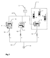
- the telecommunications network shown schematically in Fig. 1 consists of a cordless telecommunications system 1 and several telecommunications terminals 9 to 11.
- An analog network termination 3 is connected via an exchange line 2 to the public switched telephone network.
- the cordless telephone system consists of a base station 5 and several cordless subscriber terminals 6 to 8, which are in radio communication with the base station 5. All telecommunications terminals 9 to 11 and the base station 5 are connected to the network termination 3 by a telephone line 4. They are supplied with current via respective power cables 12.
- the respective power cables 12 are connected to an in-house power line 13 which is supplied with current via an electric power meter 14.
- the individual telecommunications terminals 9 to 11 are a telephone answering set 9, a telephone 10 connected thereto, and a fax machine 11. This is one embodiment of the invention; in other embodiments, other telecommunications terminals, such as a personal computer (PC) or a printer, may be provided.
- PC personal computer
- the number of telecommunications terminals connected in parallel to the network termination 3 is not limited.
- An individual identification signal is assigned to each of the telecommunications terminals 9 to 11 and to each of the cordless terminals 6 to 8. This enables a subscriber external to the network termination 3 to selectively address one of the cordless subscriber terminals 6 to 8 or one of the telecommunications terminals 9 to 11 of the telecommunications network. If a single analog exchange line 2 is present, this is possible if the service provider (e.g., DeutscheInstitut) assigns not only one telephone number per analog exchange line but, possibly for a certain extra charge, additional, virtual telephone numbers. It then rests with the owner of the telecommunications network to determine which telephone number to assign to which telecommunications terminal.
- Fig. 2 is a schematic of a first variant of the telecommunications network, comprising the cordless telecommunications system 1 and a telephone 10 connected in parallel with the cordless telecommunications system 1 and coupled to the network termination 3.
- a connection is established between the external subscriber and the cordless subscriber terminal 6, the call being switched through on the telephone line 4 to the base station 5 "a", from where it is transmitted to the cordless subscriber terminal 6 by radio, "b".
- the modem contained in the telephone 10 will process these second control signals d and pass them on to a processor in the telephone 10, which will determine after logic operations whether the individual identification signal of the telephone 10 is included in the second control signals "d". If so, the processor of the telephone 10 will transfer instructions which will activate a ringing signal, for example, and cause information, such as the name of the called subscriber, to be presented on a display of the telephone 10. After the subscriber at the telephone 10 has lifted the handset, the call from the external subscriber is automatically transferred to the telephone 10. A connection "e" then exists between the external subscriber and the subscriber at the telephone 10 over the telephone line 4. This transfer is effected without the external subscriber having to operate anything.
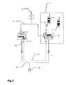
- the subscriber at the cordless subscriber terminal 6 can use the in-house power line to retrieve operating data from one of the telecommunications terminals of the telecommunications network, in this case the fax machine 11, or to change such operating data. To do this, the subscriber at the cordless subscriber terminal 6 will enter a corresponding combination of digits. This causes first control signals "c" to be sent to the base station 5, which activate the modem contained in the base station. The modem generates second control signals "d", which are transmitted over the in-house power line 13. The modem of the fax machine 11 receives these second control signals "d” and processes them before they are passed on to the processor of the fax machine 11.
- a connection can be established between the cordless telecommunications terminal 6 and the fax machine 11 in order to retrieve and/or change operating data of the fax machine 11.
- the telephone line 4 will remain idle, so that an external subscriber can address either a second cordless terminal 7 or, for example, the fax machine itself over the telephone line 4. This enables the subscriber of the cordless telephone terminal 6 to determine, for example, whether a fax has arrived at the fax machine 11, without seizing the telephone line 4.
- the second control signals "d" (Fig. 2 or Fig. 3), which are transferred over the in-house power line 13 and serve to establish a call between a cordless subscriber terminal 6 to 8 of the cordless telecommunications system 1 and a telecommunications terminal 9 to 11 of the telecommunications network, cannot leave the in-house power line 13 through the electric power meter 14. This ensures, on the one hand, that these second control signals d do not interfere with the supply of power and, on the other hand, that no third party can intercept them outside the in-house power line 13.
Landscapes
- Engineering & Computer Science (AREA)
- Computer Networks & Wireless Communication (AREA)
- Signal Processing (AREA)
- Power Engineering (AREA)
- Mobile Radio Communication Systems (AREA)
- Telephone Function (AREA)
- Telephonic Communication Services (AREA)
- Cable Transmission Systems, Equalization Of Radio And Reduction Of Echo (AREA)
Abstract
The invention relates to a method of establishing a call between a cordless subscriber terminal (6-8) and another subscriber terminal (6-11), with each of the two subscriber terminals (6-11) being addressed via an individual identification signal, and both being addressed from outside via the same analog network termination (3). The method includes the steps of: generating first control signals at the cordless subscriber terminal (6-8); activating, in response to these first control signals received by the base station (5), means contained in the base station (5) for generating second control signals to be transferred over an in-house power line (13); transmitting the second control signals over the in-house power line (13); detecting the second control signals at the called subscriber terminal (6-11); and accepting the call at the called subscriber terminal (6-11). <IMAGE>
Description
This invention relates to a method of establishing a call between a cordless
subscriber terminal and another subscriber terminal, as well as to a cordless
telecommunications system, a cordless subscriber terminal, and a base station
for carrying out this method.
The invention starts from an internal development which is based on a
cordless telecommunications system consisting of a base station and a number
of cordless subscriber terminals. The base station is connected via a network
termination to a single exchange line. Nevertheless, an external subscriber can
selectively call one of the cordless subscriber terminals. To make this possible,
each subscriber terminal is identified by an identification signal. This
identification signal generally forms part of the calling line identification, which
is transmitted to the called subscriber terminal after the first signal (ringing
pulse alerting signal). The base station, which recognizes the cordless
subscriber terminals, is provided with means for detecting and generating such
identification signals. These means generally include a modem which can
demodulate the identification signal and pass it on to a processor. After a
logic operation, such as a comparison between the demodulated identification
signal and the preset individual identification signals of the cordless subscriber
terminals, which are stored in a memory, it is determined to which of the
cordless subscriber terminals the incoming call is directed. Depending on the
result of this comparison, the base station will send a signal which will activate
an alarm, e.g., an audible alarm, at the called cordless subscriber terminal
only.
The assignment of individual identification signals to the cordless subscriber
terminals offers an essential advantage, particularly for analog exchange
lines. Today such a telecommunications system often forms part of a
telecommunications network. Other telecommunications terminals may be
connected in parallel with the base station and coupled to the same network
termination. The telecommunications network may be composed, for example,
of the telecommunications system, comprising the base station and the
cordless subscriber terminals, a further telephone, a fax machine, and a
telephone answering set. If such telecommunications terminals, which are
connected in parallel to the same network termination, and the cordless
subscriber terminal are identified by an identification signal, an external
subscriber can reach either a given cordless subscriber terminal or one of the
other subscriber terminals.
Still, the use of such a telecommunications network is greatly restricted by the
connection to a single analog exchange line. For example, a subscriber of the
telecommunications network whose number has been dialed by an external
subscriber by mistake cannot transfer the call to another telecommunications
terminal of the telecommunications network. The external subscriber has no
choice but to terminate the first call and dial anew. Nor is it possible with such
a telecommunications network to make a call to an external subscriber if a
subscriber with a cordless subscriber terminal is engaged in retrieving data
from one of the telecommunications terminals of the telecommunications
network or in changing such data. If, for example, this subscriber wants to
check by means of his cordless subscriber terminal whether a fax has arrived
at the fax machine of the telecommunications network, the telephone line will
unnecessarily remain busy for the external subscriber.
It is the object of the invention to render connections between a cordless
subscriber terminal and a further subscriber terminal more flexible, with each
of the two subscriber terminals being addressed via an individual identification
signal and from outside via the same network termination.
According to the invention, this object is attained by a method according to the
teaching of claim 1 and by a cordless telecommunications system, a cordless
subscriber terminal, and a base station according to the teachings of claims 4,
5, and 6, respectively.
The basic idea of the invention lies in the utilization of the fact that cordless
subscriber terminals of a telecommunications system which are identified by
individual identification signals require a base station which is equipped with a
modem and is therefore supplied with current. Since that is also the case for
all telecommunications terminals of the telecommunications network, such
telecommunications terminals and the base station of the telecommunications
system are connected to an in-house power line. The activation by a cordless
subscriber terminal of control signals generated in the base station, which are
transferred over the power line, makes it possible to establish a call to a
telecommunications terminal of the telecommunications network without using
the telephone line. If a single exchange line is present, only such a call
establishment makes it possible to transfer a call between an external
subscriber and a cordless subscriber terminal to a telecommunications
terminal of the telecommunications network without having to terminate the
call with the external subscriber.
These control signals, which are transferred over the in-house power line and
may contain the identification signal of the telecommunications terminal to be
addressed, can also be used to retrieve operating data from the called
telecommunications terminal and, if necessary, to change this data. This is
particularly advantageous in a telecommunications network in which the
individual telecommunications terminals are located in several separate
rooms.
If such a cordless telecommunications system and such telecommunications
terminals are used to implement a telecommunications network, it is only
necessary to provide new activatable or deactivatable instruction sets for the
telecommunications terminals. The instruction sets are stored in a memory and
are made available to the modems of the respective telecommunications
terminals to permit the generation of control signals to be transferred over the
in-house power line. If these instruction sets are activated by a cordless
subscriber terminal, the modem of the base station which is in radio
communication with this cordless subscriber terminal will generate control
signals and transmit them over the in-house power line. These instruction sets
can be stored in a memory of the base station and be made available to the
respective cordless subscriber terminals by radio. It is also possible to store the
instruction sets in a nonvolatile memory of a telecommunications terminal
implemented as a personal computer (PC) before making it available to the
base station. This illustrates the small amount of complexity involved in
upgrading a telecommunications network in such a way that it offers the new
services according to the invention, for example by reading the instruction set
from a storage medium via the disk drive of the PC and storing it in the
nonvolatile memory of the latter.
Further advantageous features of the invention are defined in the dependent
claims and will become apparent from the following description and the
drawings.
One embodiment of the invention will now be explained in more detail with
reference to the accompanying drawings, in which:
- Fig. 1
- is a schematic of a telecommunications network including a cordless telecommunications system;
- Fig. 2
- is a schematic of a first variant of the telecommunications network of Fig. 1; and
- Fig. 3
- is a schematic of a second variant of the telecommunications network of Fig. 1.
The telecommunications network shown schematically in Fig. 1 consists of a
cordless telecommunications system 1 and several telecommunications
terminals 9 to 11. An analog network termination 3 is connected via an
exchange line 2 to the public switched telephone network. The cordless
telephone system consists of a base station 5 and several cordless subscriber
terminals 6 to 8, which are in radio communication with the base station 5. All
telecommunications terminals 9 to 11 and the base station 5 are connected to
the network termination 3 by a telephone line 4. They are supplied with
current via respective power cables 12. The respective power cables 12 are
connected to an in-house power line 13 which is supplied with current via an
electric power meter 14.
The individual telecommunications terminals 9 to 11 are a telephone
answering set 9, a telephone 10 connected thereto, and a fax machine 11.
This is one embodiment of the invention; in other embodiments, other
telecommunications terminals, such as a personal computer (PC) or a printer,
may be provided. The number of telecommunications terminals connected in
parallel to the network termination 3 is not limited.
An individual identification signal is assigned to each of the
telecommunications terminals 9 to 11 and to each of the cordless terminals 6
to 8. This enables a subscriber external to the network termination 3 to
selectively address one of the cordless subscriber terminals 6 to 8 or one of the
telecommunications terminals 9 to 11 of the telecommunications network. If a
single analog exchange line 2 is present, this is possible if the service provider
(e.g., Deutsche Telekom) assigns not only one telephone number per analog
exchange line but, possibly for a certain extra charge, additional, virtual
telephone numbers. It then rests with the owner of the telecommunications
network to determine which telephone number to assign to which
telecommunications terminal.
Fig. 2 is a schematic of a first variant of the telecommunications network,
comprising the cordless telecommunications system 1 and a telephone 10
connected in parallel with the cordless telecommunications system 1 and
coupled to the network termination 3. After an external subscriber has called
the cordless subscriber terminal 6, and the called subscriber terminal has sent
a call accepted signal, a connection is established between the external
subscriber and the cordless subscriber terminal 6, the call being switched
through on the telephone line 4 to the base station 5 "a", from where it is
transmitted to the cordless subscriber terminal 6 by radio, "b". If it turns out
that the call has to be transferred to the telephone 10, the subscriber at the
cordless subscriber terminal 6, for example by entering a combination of
digits, will generate first control signals "c", which are transmitted to the base
station 5 by radio. Reception of these first control signals "c" by the base
station 5 activates means contained in the base station for generating second
control signals "d", which are transferred over the in-house power line 13.
Together with the generation of the second control signals at the latest, the
individual identification signal of the called subscriber terminal 10 is
generated. These second control signals d spread through the power line 10
and thus reach all telecommunications terminals connected to the power line.
The modem contained in the telephone 10 will process these second control
signals d and pass them on to a processor in the telephone 10, which will
determine after logic operations whether the individual identification signal of
the telephone 10 is included in the second control signals "d". If so, the
processor of the telephone 10 will transfer instructions which will activate a
ringing signal, for example, and cause information, such as the name of the
called subscriber, to be presented on a display of the telephone 10. After the
subscriber at the telephone 10 has lifted the handset, the call from the external
subscriber is automatically transferred to the telephone 10. A connection "e"
then exists between the external subscriber and the subscriber at the telephone
10 over the telephone line 4. This transfer is effected without the external
subscriber having to operate anything.
As shown in Fig. 3, the subscriber at the cordless subscriber terminal 6 can use
the in-house power line to retrieve operating data from one of the
telecommunications terminals of the telecommunications network, in this case
the fax machine 11, or to change such operating data. To do this, the
subscriber at the cordless subscriber terminal 6 will enter a corresponding
combination of digits. This causes first control signals "c" to be sent to the
base station 5, which activate the modem contained in the base station. The
modem generates second control signals "d", which are transmitted over the
in-house power line 13. The modem of the fax machine 11 receives these
second control signals "d" and processes them before they are passed on to
the processor of the fax machine 11. After the processor has determined that
these second control signals "d" are assigned to the fax machine 11, a
connection can be established between the cordless telecommunications
terminal 6 and the fax machine 11 in order to retrieve and/or change
operating data of the fax machine 11. During that time, the telephone line 4
will remain idle, so that an external subscriber can address either a second
cordless terminal 7 or, for example, the fax machine itself over the telephone
line 4. This enables the subscriber of the cordless telephone terminal 6 to
determine, for example, whether a fax has arrived at the fax machine 11,
without seizing the telephone line 4.
The second control signals "d" (Fig. 2 or Fig. 3), which are transferred over the
in-house power line 13 and serve to establish a call between a cordless
subscriber terminal 6 to 8 of the cordless telecommunications system 1 and a
telecommunications terminal 9 to 11 of the telecommunications network,
cannot leave the in-house power line 13 through the electric power meter 14.
This ensures, on the one hand, that these second control signals d do not
interfere with the supply of power and, on the other hand, that no third party
can intercept them outside the in-house power line 13.
Claims (6)
- A method of establishing a call between a cordless subscriber terminal (6-8) and another subscriber terminal (6-11), with each of the two subscriber terminals (6-11) being addressed via an individual identification signal, and both subscriber terminals (6-11) being addressed from outside via the same analog network termination (3), said method comprising the steps of:dialing the number of the other subscriber terminal (6-11) at the cordless subscriber terminal (6-8);generating first control signals at the cordless subscriber terminal (6-8);sending said first control signals to a base station (5) connected to the analog network termination (3);receiving the first control signals at the base station (5);activating, in response to said first control signals, means contained in the base station (5) for generating second control signals to be transferred over an in-house power line (13);transmitting the second control signals over the in-house power line (13);detecting the second control signals at the other subscriber terminal (6-11); andaccepting the call at the other subscriber terminal (6-11).
- A method of establishing a call as claimed in claim 1, characterized in that the individual identification signal of the other subscriber terminal (6-11) is generated together with the generation of the second control signals at the latest.
- A method of establishing a call as claimed in claim 1, characterized in that it serves to transfer a call existing between the cordless subscriber terminal (6-8) and an external subscriber.
- A cordless telecommunications system (1) comprising:
at least one cordless subscriber terminal (6-8) which is addressable via an individual identification signal and includes means
whereby it can generate first control signals; and a base station (5) comprising
an interface to a network termination (3), an interface to an in-house power line (13), a receiver for said first control signals, and additional means,
the additional means being activatable by the first control signals to generate second control signals to be transmitted over the in-house power line (13). - A cordless subscriber terminal (6-8) which
is addressable via an individual identification signal and includes means
whereby it can generate first control signals for establishing a call via a base station (5) comprising
an interface to a network termination (3), an interface to an in-house power line (13), a receiver for said first control signals, and additional means,
the additional means being activatable by the first control signals to generate second control signals to be transmitted over the in-house power line (13). - A base station (5) comprising:
a receiver for signals transmitted by a cordless subscriber terminal (6-8);
an interface to a network termination (3);
an interface to an in-house power line (13); and additional means,
the additional means being activatable by first control signals transmitted by a cordless telecommunications terminal (6-8) and received by the base station (5) to generate second control signals to be transmitted over the in-house power line (13).
Priority Applications (4)
| Application Number | Priority Date | Filing Date | Title |
|---|---|---|---|
| EP99440225A EP1076443A1 (en) | 1999-08-13 | 1999-08-13 | Method of establishing a call between a cordless terminal and another external terminal, with an analog network and the power line |
| JP2000224713A JP2001086567A (en) | 1999-08-13 | 2000-07-26 | Method for establishing a call between a cordless subscriber terminal and another subscriber terminal, and cordless communication system, cordless subscriber terminal and base station therefor |
| SG200004442A SG86430A1 (en) | 1999-08-13 | 2000-08-11 | Method of establishing a call between a cordless subscriber terminal and another subscriber terminal, as well as a cordless telecommunications system, a cordless subscriber terminal, and a base station therefor |
| CN00122749.1A CN1284829A (en) | 1999-08-13 | 2000-08-11 | Method for setting up call and cordless telecommunication system, cordless user terminal and base station |
Applications Claiming Priority (1)
| Application Number | Priority Date | Filing Date | Title |
|---|---|---|---|
| EP99440225A EP1076443A1 (en) | 1999-08-13 | 1999-08-13 | Method of establishing a call between a cordless terminal and another external terminal, with an analog network and the power line |
Publications (1)
| Publication Number | Publication Date |
|---|---|
| EP1076443A1 true EP1076443A1 (en) | 2001-02-14 |
Family
ID=8242368
Family Applications (1)
| Application Number | Title | Priority Date | Filing Date |
|---|---|---|---|
| EP99440225A Withdrawn EP1076443A1 (en) | 1999-08-13 | 1999-08-13 | Method of establishing a call between a cordless terminal and another external terminal, with an analog network and the power line |
Country Status (4)
| Country | Link |
|---|---|
| EP (1) | EP1076443A1 (en) |
| JP (1) | JP2001086567A (en) |
| CN (1) | CN1284829A (en) |
| SG (1) | SG86430A1 (en) |
Cited By (1)
| Publication number | Priority date | Publication date | Assignee | Title |
|---|---|---|---|---|
| FR2844125A1 (en) * | 2002-09-03 | 2004-03-05 | Inventel Systemes | CENTRAL BASE FOR LOCAL PRIVATE RADIOCOMMUNICATION NETWORK AND RADIOCOMMUNICATION DEVICE INCLUDING SUCH A BASE. |
Citations (2)
| Publication number | Priority date | Publication date | Assignee | Title |
|---|---|---|---|---|
| EP0668686A1 (en) * | 1994-02-17 | 1995-08-23 | GRID Telecom Systems B.V. | Home telephone system |
| GB2295521A (en) * | 1994-11-24 | 1996-05-29 | Plessey Telecomm | Improvements in or relating to line communication systems |
-
1999
- 1999-08-13 EP EP99440225A patent/EP1076443A1/en not_active Withdrawn
-
2000
- 2000-07-26 JP JP2000224713A patent/JP2001086567A/en not_active Withdrawn
- 2000-08-11 CN CN00122749.1A patent/CN1284829A/en active Pending
- 2000-08-11 SG SG200004442A patent/SG86430A1/en unknown
Patent Citations (2)
| Publication number | Priority date | Publication date | Assignee | Title |
|---|---|---|---|---|
| EP0668686A1 (en) * | 1994-02-17 | 1995-08-23 | GRID Telecom Systems B.V. | Home telephone system |
| GB2295521A (en) * | 1994-11-24 | 1996-05-29 | Plessey Telecomm | Improvements in or relating to line communication systems |
Cited By (2)
| Publication number | Priority date | Publication date | Assignee | Title |
|---|---|---|---|---|
| FR2844125A1 (en) * | 2002-09-03 | 2004-03-05 | Inventel Systemes | CENTRAL BASE FOR LOCAL PRIVATE RADIOCOMMUNICATION NETWORK AND RADIOCOMMUNICATION DEVICE INCLUDING SUCH A BASE. |
| WO2004023768A1 (en) * | 2002-09-03 | 2004-03-18 | Inventel Systemes | Central base for private radiocommunication local network and radiocommunication device comprising same |
Also Published As
| Publication number | Publication date |
|---|---|
| CN1284829A (en) | 2001-02-21 |
| SG86430A1 (en) | 2002-02-19 |
| JP2001086567A (en) | 2001-03-30 |
Similar Documents
| Publication | Publication Date | Title |
|---|---|---|
| US5619725A (en) | Method for auxiliary software providing instruction for facsimile modem to simulate a telephone communication while connecting to store and forward computer to receive communication | |
| US5631950A (en) | Transmission of data message during silent intervals of ringing for selection of terminal equipment | |
| JP2002271478A (en) | Telephone and method for controlling connection of call | |
| EP1076443A1 (en) | Method of establishing a call between a cordless terminal and another external terminal, with an analog network and the power line | |
| US6490346B2 (en) | Apparatus and method for providing music-on-hold service in key telephone system | |
| EP1076444B1 (en) | Telecommunication terminal communicating signaling information through the power line with other terminals connected in parallel to the same network termination | |
| US5844968A (en) | Interfacing between independent voice mail system and exchange | |
| JPS613548A (en) | Facsimile communication representative connecting system | |
| JP3333882B2 (en) | Communication system, terminal-side communication device in communication system, and partner communication device in communication system | |
| JPH0730663A (en) | Voicemail devices and card phones | |
| JP2002209017A (en) | Private branch exchange, automatic answering apparatus and automatic answering private branch exchange system | |
| HK1033407A (en) | Method of establishing a call between a cordless subscriber terminal and another subscriber terminal, as well as a cordless telecommunications system, a cordless subscriber terminal, and a base station therefor | |
| KR950003687B1 (en) | Call forwarding method by specifing acertain trunk | |
| EP0571345A2 (en) | Centralised telefax reception | |
| JP3041675U (en) | Data transfer device | |
| JP2597555B2 (en) | Digital switching system | |
| KR100223649B1 (en) | Message receiving method in facsimile device | |
| JP2001358833A (en) | Key telephone system | |
| US6614547B1 (en) | Cordless facsimile system with telephone answering function and method for controlling the same | |
| JPH0351344B2 (en) | ||
| JP2001257808A (en) | Communication terminal device | |
| KR100270735B1 (en) | Method for transfer a incoming call to voice mail system in pabx system | |
| JPH0488740A (en) | Extension call system | |
| JPH10136190A (en) | Facsimile communication management device | |
| JPH06269034A (en) | Communication control method in in-premises system |
Legal Events
| Date | Code | Title | Description |
|---|---|---|---|
| PUAI | Public reference made under article 153(3) epc to a published international application that has entered the european phase |
Free format text: ORIGINAL CODE: 0009012 |
|
| AK | Designated contracting states |
Kind code of ref document: A1 Designated state(s): AT BE CH CY DE DK ES FI FR GB GR IE IT LI LU MC NL PT SE |
|
| AX | Request for extension of the european patent |
Free format text: AL;LT;LV;MK;RO;SI |
|
| 17P | Request for examination filed |
Effective date: 20010317 |
|
| AKX | Designation fees paid |
Free format text: AT BE CH CY DE DK ES FI FR GB GR IE IT LI LU MC NL PT SE |
|
| STAA | Information on the status of an ep patent application or granted ep patent |
Free format text: STATUS: THE APPLICATION IS DEEMED TO BE WITHDRAWN |
|
| 18D | Application deemed to be withdrawn |
Effective date: 20030301 |