EP1076401B1 - Winding cores with stratification motion - Google Patents
Winding cores with stratification motion Download PDFInfo
- Publication number
- EP1076401B1 EP1076401B1 EP00117129A EP00117129A EP1076401B1 EP 1076401 B1 EP1076401 B1 EP 1076401B1 EP 00117129 A EP00117129 A EP 00117129A EP 00117129 A EP00117129 A EP 00117129A EP 1076401 B1 EP1076401 B1 EP 1076401B1
- Authority
- EP
- European Patent Office
- Prior art keywords
- winder
- assembly
- support
- movement
- radial movement
- Prior art date
- Legal status (The legal status is an assumption and is not a legal conclusion. Google has not performed a legal analysis and makes no representation as to the accuracy of the status listed.)
- Expired - Lifetime
Links
- 230000033001 locomotion Effects 0.000 title claims abstract description 71
- 238000004804 winding Methods 0.000 title claims abstract description 16
- 238000013517 stratification Methods 0.000 title description 20
- 238000013519 translation Methods 0.000 claims description 12
- 230000014616 translation Effects 0.000 description 11
- 230000000712 assembly Effects 0.000 description 2
- 238000000429 assembly Methods 0.000 description 2
- 230000005540 biological transmission Effects 0.000 description 2
- 230000001360 synchronised effect Effects 0.000 description 2
- 230000002452 interceptive effect Effects 0.000 description 1
- 230000002250 progressing effect Effects 0.000 description 1
- 230000003068 static effect Effects 0.000 description 1
Images




Classifications
-
- H—ELECTRICITY
- H02—GENERATION; CONVERSION OR DISTRIBUTION OF ELECTRIC POWER
- H02K—DYNAMO-ELECTRIC MACHINES
- H02K15/00—Processes or apparatus specially adapted for manufacturing, assembling, maintaining or repairing of dynamo-electric machines
- H02K15/08—Forming windings by laying conductors into or around core parts
- H02K15/095—Forming windings by laying conductors into or around core parts by laying conductors around salient poles
-
- Y—GENERAL TAGGING OF NEW TECHNOLOGICAL DEVELOPMENTS; GENERAL TAGGING OF CROSS-SECTIONAL TECHNOLOGIES SPANNING OVER SEVERAL SECTIONS OF THE IPC; TECHNICAL SUBJECTS COVERED BY FORMER USPC CROSS-REFERENCE ART COLLECTIONS [XRACs] AND DIGESTS
- Y10—TECHNICAL SUBJECTS COVERED BY FORMER USPC
- Y10T—TECHNICAL SUBJECTS COVERED BY FORMER US CLASSIFICATION
- Y10T29/00—Metal working
- Y10T29/49—Method of mechanical manufacture
- Y10T29/49002—Electrical device making
- Y10T29/49009—Dynamoelectric machine
Definitions
- the present application relates to winding coils of wire onto poles of dynamo-electric cores. More particularly, the coils are wound directly into the slots of cores by means of needles which dispense wires. The wires are each drawn from tensioners.
- US 3,411,725 discloses a winder having a plurality of needles capable of rotational and translational movements with respect to the core while stratifying the wire along the poles of the core.
- the stratification movement of the needles is mechanically derived from the rotational movement of the needles.
- JP 60 016161 discloses a winding apparatus capable of rotational and translational movements with respect to the core while stratifying the wire along the poles of the core.
- the translational movement is obtained by translating the core
- the rotational movement is obtained by rotating the core
- the stratification movement is obtained by a motor that is not used driving the other movements.
- a winding apparatus preferably capable of rotational, translational and radial movements with respect to the poles of the core.
- This stratification movement can be considered to be a radial movement that moves the winding needle along the radial extension of the poles.
- This stratification allows for predetermined placement of the wire. Pre-determined placement of the wire preferably results in deeper and denser winding of wire.
- a winder for winding wires onto a coil support portion of a dynamo-electric core is provided according to claim 1.
- FIG. 1 illustrates an axial end 10' of core 10.
- Core 10 includes a pile of laminated portions, having an axial configuration like 10', stacked for a certain length into the page. (Reference to the "page” as used herein indicates the plane of the drawing page of the FIGS.). Such a length is often referred to as the "height of the core”.
- the actual coils 102, 104 and 106 are wound around poles 108, by using needles 11, 12, and 13 which dispense wires 111, 112 and 113, respectively, onto specific poles, as illustrated in FIG. 1 .
- the wire turns 121, 122 and 123 of the coils become stratified along poles 108. This means that each wire turn tends to occupy an individual layer along the poles.
- the turns are illustrated crossing the end faces, similar to end face 132, of the poles.
- the stratification shown in FIG. 1 is such that the turns are preferably wound on layers progressing inwardly towards the center of core 10 -- i.e., at longitudinal axis 131.
- Each turn is also preferably wound around the pole sides similar to sides 134 and 136, and across opposite faces similar to face 132.
- needles 11, 12, and 13 are provided with translation strokes, parallel to sides 134 and 136, and into the page. During these strokes, the needle tips 142, 144 and 146 are partially inserted in slots 152, 153 and 154 of core 10 to place the wires along the respective pole sides. At the end of the translation strokes, needle tips 142, 144 and 146 are located beyond the end faces of core 10.
- needles 11, 12 and 13 can be rotated with respect to longitudinal axis 131 of core 10, in order to place the wires across the end faces of the poles.
- rotational movement preferably indicates that the core may be rotated around longitudinal axis 131, while the needles remain stationary.
- needle tips 142, 144 and 146 may be aligned with adjacent slots, where they can start opposite translation strokes.
- needles 11, 12 and 13 accomplish opposite translation strokes with their tips partially inserted in the adjacent slots of the core in order to place the wires along the nearby pole sides.
- tips 142, 144 and 146 are located beyond the end faces of the core, and out of the page. Then, an opposite rotation can take place to align the tips with the slot where the motions started.
- Such a combination of motions places single turns of coils, such as coils 102, 104 and 106, completely around the poles.
- the combination of motions needs to be repeated for a number of times equal to the number of turns.
- the combination of motions also must be repeated for the number of layers of turns that are wound around the poles.
- the stratification of the turns shown in FIG. 1 can be implemented by moving the needles along radiuses R1, R2 and R3 (respectively for needles 11, 12 and 13) of core 10.
- the movements along the radiuses preferably occur incrementally along the radius length. The incremental movement can be implemented at the start of each new turn.
- a correctly obtained stratification is of great importance for guaranteeing that the turns are tightly wound, and of the same length.
- Orderly stratification of the wires achieves more compact coils, which ultimately means that more turns can be wound in the same slot space, while preventing turns of adjacent poles from interfering with each other.
- the present invention provides a machine which achieves such a stratification. Furthermore, the machine of the present invention is able to have multiple needles accomplish stratification, substantially simultaneously, along respective poles. This achievement is made possible even for poles which are at a close angular distance from each other around the center of core 10.
- the machine is programmable so that the stratification can be achieved in a variable and predetermined manner, depending on the requirements of the core and the coils which need to be wound.
- coils 102, 104 and 106 can be simultaneously wound by using respective and separate needles for each pole.
- the motions of the needles can also preferably be synchronized with respect to each other. Winding multiple coils, by means of a plurality of needles operating substantially simultaneously, reduces the time required to wind the totality of coils present in the core.
- the shape of the needles is preferably a "V" configuration at the needle base because of the relatively small angular spacing made available by the distance existing between the poles.
- FIG. 2 is a partial section view as seen from direction 2 - 2 of FIG. 1 , showing the apparatus of this invention for causing the needles to move with translational, rotational and radial -- i.e., stratification -- motions.
- FIG. 2A shows a sectional view of the entire assembly 20.
- FIG. 3 is a section view similar to FIG. 2 and represents a continuation of FIG. 2 (towards the left of the page containing FIG. 2 ). Furthermore, FIG. 3 shows the completion of assembly 20.
- FIG. 4 is a view from direction 4 - 4 of FIG. 3 . Assembly 20 is partially visible in FIG. 2 .
- FIG. 2 core 10 and the needles of FIG. 1 have been rotated to bring needle 12 on axis 131.
- Three distinct assemblies 20 shown in FIG. 3 ), 21 (shown in FIG. 2a ) and 22 respectively generate the translation strokes, relative rotation motions and the radial increments for winding of the turns.
- Each of the assemblies preferably provides for the independent operation of each other assembly.
- FIG. 2 illustrates the connection of needle 12 (in partial section view) to tube 12', by means of bolt 12" screwed into an end cap of tube 12'. These tubes act as support members for the needles. Tip 144 of needle 12, which is perpendicular to the length of needle 12, is clearly visible in FIG. 2 . Needles 11 and 13 will be connected in a similar manner to tubes 11' and 13'. To avoid complicating FIG. 2 , needles 11 and 13 (which are out of the plane of FIG. 2 ) have been omitted from FIG. 2 .
- Wires 111, 112 and 113 are threaded through the respective needles to reach the core as shown in FIG. 1 .
- Wires come from a respective supply reel placed to the left of FIG. 3 and enter the tubes through nozzles like 12''', shown for tube 12' in FIG. 3 .
- needles are provided with bent portions -- e.g., bent portion 222 shown in FIG. 2 .
- tubes 11', 12' and 13' are connected to slide members 24, 25 and 26, respectively.
- Slide members 24, 25 and 26 have narrow portions which are guided to move in radial directions R1, R2 and R3, respectively, by means of respective slots 24', 25' and 26'. These slots are preferably machined in upstanding plate 27.
- Upstanding plate 27 is preferably bolted to threaded sleeve 28 by means of bolts (not shown).
- Plate 27 is provided with dovetail recesses 27' and 27" that receive corresponding guide male portions 31' and 31" of a bench portion of casing 31. This configuration allows plate 27 to translate in directions T and T', parallel to axis 131. (A portion of plate 27, as well as the bench portion of casing 31 has been omitted for the sake of clarity.)
- Sleeve 28 is threaded onto threaded bar 29, which, in turn, is supported on bearing support 30 of casing 31 ( see FIG. 3 ).
- End 29' of threaded bar 29 carries pulley 32 of belt transmission 32', which leads to electric motor 33. Electric motor 33 can be controlled to turn threaded bar 29 for a predetermined number of revolutions. The result will be translation of upstanding plate 27, and consequently of tubes 11', 12', and 13' in directions T and T' for pre-determined stroke lengths.
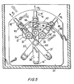
- FIG. 5 is a partial section view from directions 5 - 5 of FIG. 2 .
- Tubes 11', 12' and 13' are supported in preferably cylindrical guide sleeves 35, 36 and 37, respectively.
- Tubes 11', 12' and 13' are carried by bushes -- e.g., bushes 38 and 39 of guide sleeve 35, which support tube 12', as shown in FIG. 2 .
- the bushes allow the tubes to translate in directions T and T', within guide sleeves 35, 36 and 37, when upstanding plate 27 is moved backwards and forwards by electric motor 33.
- Guide sleeves 35, 36 and 37 are parts of support arms 35', 36' and 37', respectively.
- support arms 35', 36' and 37' are contained in different, although parallel, planes with respect to the plane of the page in FIG. 5 . Furthermore, 35', 36' and 37' cross each other as shown in FIG. 5 . Support arms 35', 36' and 37' can move along radii R1, R2 and R3 to accomplish the radial motion required for stratification by being supported respectively on respective guide tracks 40, 41 and 42. Preferably, the radial movement of each of the support arms occurs substantially simultaneously.
- the guide tracks consist of opposite portions -- e.g., 41' and 41" of guide track 41 -- extending along radii R1, R2 and R3. The guide tracks are assembled to an upright portion of casing 31.
- guide tracks 40, 41, and 42 are also located on different, but parallel planes with respect to each other and with respect to the page of FIG. 5 (and as shown in FIG. 1 ), in order to conform to the planes containing support arms 35', 36' and 37'.
- FIG. 6 is a view from direction 6 - 6 of FIG. 2 showing guide portions 40', 41' and 42' of guide tracks 40, 41 and 42 in perspective view, contained in their respective and different planes.
- Support arms 35', 36' and 37' include pairs of rollers 43, 44, and 45, respectively, for movably connecting to biting cam members 46, 47 and 48, respectively.
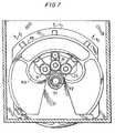
- FIG. 7 is a view from direction 7 - 7 of FIG. 2 .
- Cam disk 49 is shown in FIG. 2 , 6 and 7 .
- cam members 46, 47 and 48 have different and respective extensions from cam disk 49 in order to reach pairs of rollers pairs of rollers 43, 44, and 45.
- Cam disk 49 is supported by shaft 49' on bearing assembly 50 of casing 31.
- Bearing assembly 50 allows cam disk 49 to rotate around axis 131.
- Cam disk 49 preferably is provided with a gear profile on its outer circumference, which meshes with pinion gear 52 of electric motor 53.
- Electric motor 53 is preferably supported by casing 31.
- cam disk 49 is provided with an aperture 749 to allow passage of guide sleeves 35, 36 and 37. Again, the size of aperture 749 should preferably provide for clearance with respect to movement of guide sleeves 35, 36 and 37 along radiuses R1, R2 and R3 during the radial -- i.e., stratification -- motion.
- FIG. 8 shows a continuation towards the right of FIG. 2 .
- FIG. 8 shows core 10, which is being wound.
- Core 10 can be supported in core casing 60 of a vertical round table 61.
- FIG. 8 also illustrates assembly 21. Assembly 21 preferably accomplishes the relative rotation motions.
- Core casing 60 preferably maintains core 10 centered on axis 131 of casing 31. This centers radii R1, R2 and R3 of core 10 on axis 131, as shown in the previous FIGS.
- Bearings 62 of round table 61 supports core casing 60 for rotation around axis 131. In this way, core 10 can rotate around axis 131 of casing 31 to provide the required relative rotation motions between the needles and the core, as described in the foregoing.
- the rotations are preferably imparted to core 10 casing by gear 63, which meshes with gear portion 60' provided on the external surface of core casing 60.
- Gear 63 is supported and allowed to rotate by shaft/bearing assembly 64, assembled on round table 61.
- Assembly 64 is located adjacent to core casing 60.
- Shaft 65 of shaft/bearing assembly 64 is provided with a key portion 65' which can be aligned (by rotation of round table 61) and connected to drive unit 66 of casing 31.
- Drive unit 66 preferably includes a shaft 67 driven by electric motor 68. Forward end 67' of shaft 67 has a corresponding key portion capable of connecting itself to key portion 65'. This connection occurs by shifting shaft 67 in direction Z, using air cylinder 75, which is connected to the other end of shaft 67 by means of fork joint 69.
- Shaft 67 is supported for rotation by means of support/bearing assembly 70.
- This support/bearing assembly comprises bushes for supporting movement of shaft 67 caused by air cylinder 75.
- the bushes are supported in gear tube 72, which is supported for rotation by means of bearings 73.
- Shaft 67 has key portions received in gear tube 72, for transmission of relative rotations between gear tube 72 and shaft 67.
- Gear portion 74 of gear tube 72 meshes with pinion 68' of electric motor 68.
- Rotation of electric motor 68 rotates shaft 67 which, in turn, causes core 10 to have the relative rotation motions with respect to needles 11, 12 and 13 around axis 131.
- Motor 68 can also be used to index the core when unwound poles need to be aligned with the needles.
- Motors 33, 58 and 68 can be provided with position and speed feedback sensors. Such a combination allows computer equipment to control the motors so that they achieve predetermined and programmable revolutions of rotation.
- the needles may have relative motions of translation, rotation and stratification (described in the foregoing with reference to FIG. 1 ), occurring in required timing and synchronized between each other.
- a main computer required to govern such a performance can contain the relative programs and data. Position control principles like those described in the '289 patent can be used to obtain accurate predetermined trajectories of the needles with respect to the poles.
- the same computer, or a different computer can be provided with different data when the amounts of the motions and the relative timing need to be modified -- e.g., when a different type of core needs to have winding conditions set -- i.e., requiring different translations, rotations and radial.
- cam members govern the stratification motion of the needles, although the programmable revolutions of motor 53 also influence the relative timing and speed of the needles.
- the cam members can be dismounted and substituted with others when a different motion is required.
- round table 62 can have multiple core casings carrying respective cores, each provided with a shaft/bearing assembly -- e.g., shaft/bearing assembly 64.
- cores can be fed rapidly, and in sequence, to the needles in order to be wound.
- a core casing having a core which has already been wound can align itself with another axis, where termination of the coil leads can take place by means of equipment like the one described in commonly-assigned U.S. Patent Nos. 5,065,503 , 5,245,748 , and 5,392,506 . It should be noted that all patents mentioned herein are incorporated by reference in their entirety.
- each assembly for accomplishing a particular motion is substantially physically separate from each other assembly and each assembly is capable of providing the particular motion for which it is responsible without causing the other motions to occur.
- substantially none of the equipment -- e.g., the motor -- used to cause the radial motion moves with the equipment which translates.
- the motor that provides the radial movement may be substantially static -- i.e., the motor preferably does not translate -- when the translational motion occurs.
- the stratification equipment has been conceived to move needles very close to each other (as shown in FIG. 1 ), as is the constraint given by the small angular distance existing between the poles.
Landscapes
- Engineering & Computer Science (AREA)
- Manufacturing & Machinery (AREA)
- Power Engineering (AREA)
- Manufacture Of Motors, Generators (AREA)
- Storage Of Web-Like Or Filamentary Materials (AREA)
- Windings For Motors And Generators (AREA)
- Materials For Medical Uses (AREA)
- Making Paper Articles (AREA)
Abstract
Description
- This application claims priority from United States Provisional Applications Nos.
60/148,473, filed August 12, 1999 60/214,218, filed June 23, 2000 - The present application relates to winding coils of wire onto poles of dynamo-electric cores. More particularly, the coils are wound directly into the slots of cores by means of needles which dispense wires. The wires are each drawn from tensioners.
- During winding, relative motions occur between the needles and the core in order to deliver the wires and wind them around the poles. The shapes of the slots are defined by the contours of the poles. Such motions are similar to those described in commonly-assigned
U.S. Patent No. 5,413,289 . - It would be desirable to provide a winding apparatus capable of rotational and translational movements with respect to the core while stratifying the wire along the poles of the core.
-
US 3,411,725 discloses a winder having a plurality of needles capable of rotational and translational movements with respect to the core while stratifying the wire along the poles of the core. The stratification movement of the needles is mechanically derived from the rotational movement of the needles. -
JP 60 016161 - Therefore, it is an object of the invention to provide a winding apparatus preferably capable of rotational, translational and radial movements with respect to the poles of the core. This stratification movement can be considered to be a radial movement that moves the winding needle along the radial extension of the poles. This stratification allows for predetermined placement of the wire. Pre-determined placement of the wire preferably results in deeper and denser winding of wire.
- A winder for winding wires onto a coil support portion of a dynamo-electric core is provided according to claim 1.
- The above and other objects and advantages of the present invention will be apparent upon consideration of the following detailed description, taken in conjunction with the accompanying drawings, in which like reference characters refer to like parts throughout, and in which:
-
FIG. 1 is an axial view of a core being wound according to the invention. -
FIG. 2 is a partial sectional view of an embodiment of a winder according to the invention. -
FIG. 2a is a full sectional view of an embodiment of a winder according to the invention. -
FIG. 3 is another partial sectional view of an embodiment of a winder according to the invention. -
FIG. 4 is a view from direction 4 - 4 ofFIG. 3 of a portion of the embodiment shown inFIG. 3 . -
FIG. 5 is a view from direction 5 - 5 ofFIG. 2 of a portion of the embodiment shown inFIG. 2 . -
FIG. 6 is a view from direction 6 - 6 ofFIG. 2 of the embodiment shown inFIG. 2 . -
FIG. 7 is a view from direction 7 - 7 ofFIG. 2 of a portion of the embodiment shown inFIG. 2 . -
FIG. 8 is another partial section view of an embodiment of a winder according to the invention. - A
typical core 10 wound according to the principles of the present invention is illustrated inFIG. 1. FIG. 1 illustrates an axial end 10' ofcore 10.Core 10 includes a pile of laminated portions, having an axial configuration like 10', stacked for a certain length into the page. (Reference to the "page" as used herein indicates the plane of the drawing page of the FIGS.). Such a length is often referred to as the "height of the core". - The
actual coils poles 108, by usingneedles wires 111, 112 and 113, respectively, onto specific poles, as illustrated inFIG. 1 . - The wire turns 121, 122 and 123 of the coils become stratified along
poles 108. This means that each wire turn tends to occupy an individual layer along the poles. InFIG. 1 the turns are illustrated crossing the end faces, similar toend face 132, of the poles. The stratification shown inFIG. 1 is such that the turns are preferably wound on layers progressing inwardly towards the center ofcore 10 -- i.e., atlongitudinal axis 131. Each turn is also preferably wound around the pole sides similar tosides face 132. - To begin winding of the coils shown in
FIG. 1 ,needles sides needle tips slots core 10 to place the wires along the respective pole sides. At the end of the translation strokes,needle tips core 10. - At this point,
needles longitudinal axis 131 ofcore 10, in order to place the wires across the end faces of the poles. It should be noted that, for the purpose of the embodiment described inFIGS. 1-8 , the term rotational movement preferably indicates that the core may be rotated aroundlongitudinal axis 131, while the needles remain stationary. At the end of the rotations,needle tips needles tips - Such a combination of motions places single turns of coils, such as
coils FIG. 1 can be implemented by moving the needles along radiuses R1, R2 and R3 (respectively forneedles 11, 12 and 13) ofcore 10. The movements along the radiuses preferably occur incrementally along the radius length. The incremental movement can be implemented at the start of each new turn. - Suitable criteria that can dictate when the needle should be moved along the radii, and how long the increments should be include the thickness of the wire, the dimensions and winding requirements of the poles, etc. A correctly obtained stratification is of great importance for guaranteeing that the turns are tightly wound, and of the same length. Orderly stratification of the wires achieves more compact coils, which ultimately means that more turns can be wound in the same slot space, while preventing turns of adjacent poles from interfering with each other.
- The present invention provides a machine which achieves such a stratification. Furthermore, the machine of the present invention is able to have multiple needles accomplish stratification, substantially simultaneously, along respective poles. This achievement is made possible even for poles which are at a close angular distance from each other around the center of
core 10. - In addition, the machine is programmable so that the stratification can be achieved in a variable and predetermined manner, depending on the requirements of the core and the coils which need to be wound.
- As shown in
FIG. 1 , coils 102, 104 and 106 can be simultaneously wound by using respective and separate needles for each pole. The motions of the needles can also preferably be synchronized with respect to each other. Winding multiple coils, by means of a plurality of needles operating substantially simultaneously, reduces the time required to wind the totality of coils present in the core. As illustrated inFIG. 1 , the shape of the needles is preferably a "V" configuration at the needle base because of the relatively small angular spacing made available by the distance existing between the poles. -
FIG. 2 is a partial section view as seen from direction 2 - 2 ofFIG. 1 , showing the apparatus of this invention for causing the needles to move with translational, rotational and radial -- i.e., stratification -- motions.FIG. 2A shows a sectional view of theentire assembly 20.FIG. 3 is a section view similar toFIG. 2 and represents a continuation ofFIG. 2 (towards the left of the page containingFIG. 2 ). Furthermore,FIG. 3 shows the completion ofassembly 20.FIG. 4 is a view from direction 4 - 4 ofFIG. 3 .Assembly 20 is partially visible inFIG. 2 . - In
FIG. 2 ,core 10 and the needles ofFIG. 1 have been rotated to bringneedle 12 onaxis 131.
Three distinct assemblies 20 (shown inFIG. 3 ), 21 (shown inFIG. 2a ) and 22 respectively generate the translation strokes, relative rotation motions and the radial increments for winding of the turns. Each of the assemblies preferably provides for the independent operation of each other assembly. -
Assembly 20 comprises three tubes 11', 12' and 13' carrying needles FIG. 2 illustrates the connection of needle 12 (in partial section view) to tube 12', by means ofbolt 12" screwed into an end cap of tube 12'. These tubes act as support members for the needles.Tip 144 ofneedle 12, which is perpendicular to the length ofneedle 12, is clearly visible inFIG. 2 .Needles 11 and 13 will be connected in a similar manner to tubes 11' and 13'. To avoid complicatingFIG. 2 , needles 11 and 13 (which are out of the plane ofFIG. 2 ) have been omitted fromFIG. 2 . -
Wires 111, 112 and 113 are threaded through the respective needles to reach the core as shown inFIG. 1 . Wires come from a respective supply reel placed to the left ofFIG. 3 and enter the tubes through nozzles like 12''', shown for tube 12' inFIG. 3 . To position the tips -- e.g.,tip 144 -- with respect tocore 10 as shown inFIG. 1 , needles are provided with bent portions -- e.g.,bent portion 222 shown inFIG. 2 . - The following discussion relates to tube 12' shown in
FIGS. 2 and3 but also is extended to tubes 11' and 13', though they are not shown inFIG. 3 . Each of tubes 11', 12' and 13' are connected to slidemembers Slide members upstanding plate 27. -
Upstanding plate 27 is preferably bolted to threadedsleeve 28 by means of bolts (not shown). -
Plate 27 is provided withdovetail recesses 27' and 27" that receive correspondingguide male portions 31' and 31" of a bench portion ofcasing 31. This configuration allowsplate 27 to translate in directions T and T', parallel toaxis 131. (A portion ofplate 27, as well as the bench portion ofcasing 31 has been omitted for the sake of clarity.)Sleeve 28 is threaded onto threadedbar 29, which, in turn, is supported on bearingsupport 30 of casing 31 (seeFIG. 3 ). End 29' of threadedbar 29 carriespulley 32 of belt transmission 32', which leads toelectric motor 33.Electric motor 33 can be controlled to turn threadedbar 29 for a predetermined number of revolutions. The result will be translation ofupstanding plate 27, and consequently of tubes 11', 12', and 13' in directions T and T' for pre-determined stroke lengths. -
Assembly 22, for obtaining the stratification motion is illustrated inFIGS. 2 ,5 ,6 and7 .FIG. 5 is a partial section view from directions 5 - 5 ofFIG. 2 . Tubes 11', 12' and 13' are supported in preferablycylindrical guide sleeves bushes guide sleeve 35, which support tube 12', as shown inFIG. 2 . The bushes allow the tubes to translate in directions T and T', withinguide sleeves upstanding plate 27 is moved backwards and forwards byelectric motor 33.Guide sleeves - As shown in
FIGS. 2 ,5 and6 , support arms 35', 36' and 37' are contained in different, although parallel, planes with respect to the plane of the page inFIG. 5 . Furthermore, 35', 36' and 37' cross each other as shown inFIG. 5 . Support arms 35', 36' and 37' can move along radii R1, R2 and R3 to accomplish the radial motion required for stratification by being supported respectively on respective guide tracks 40, 41 and 42. Preferably, the radial movement of each of the support arms occurs substantially simultaneously. The guide tracks consist of opposite portions -- e.g., 41' and 41" ofguide track 41 -- extending along radii R1, R2 and R3. The guide tracks are assembled to an upright portion ofcasing 31. Their opposite portions -- e.g., 41' and 41" of guide track 41 (as also shown inFIG. 2 ) -- are on respective sides ofaperture 31a ofcasing 31.Aperture 31a provides for passage ofguide sleeves guide sleeves FIG. 5 (and as shown inFIG. 1 ), in order to conform to the planes containing support arms 35', 36' and 37'. -
FIG. 6 is a view from direction 6 - 6 ofFIG. 2 showing guide portions 40', 41' and 42' of guide tracks 40, 41 and 42 in perspective view, contained in their respective and different planes. - Support arms 35', 36' and 37' include pairs of
rollers cam members -
FIG. 7 is a view from direction 7 - 7 ofFIG. 2 .Cam disk 49 is shown inFIG. 2 ,6 and7 . - As shown in
FIG. 6 ,cam members cam disk 49 in order to reach pairs of rollers pairs ofrollers -
Cam disk 49 is supported by shaft 49' on bearingassembly 50 ofcasing 31. Bearingassembly 50 allowscam disk 49 to rotate aroundaxis 131.Cam disk 49 preferably is provided with a gear profile on its outer circumference, which meshes withpinion gear 52 ofelectric motor 53.Electric motor 53 is preferably supported by casing 31. In addition,cam disk 49 is provided with anaperture 749 to allow passage ofguide sleeves aperture 749 should preferably provide for clearance with respect to movement ofguide sleeves -
FIG. 8 shows a continuation towards the right ofFIG. 2 .FIG. 8 showscore 10, which is being wound.Core 10 can be supported incore casing 60 of a vertical round table 61.FIG. 8 also illustratesassembly 21.Assembly 21 preferably accomplishes the relative rotation motions. -
Core casing 60 preferably maintainscore 10 centered onaxis 131 ofcasing 31. This centers radii R1, R2 and R3 ofcore 10 onaxis 131, as shown in the previous FIGS.Bearings 62 of round table 61supports core casing 60 for rotation aroundaxis 131. In this way,core 10 can rotate aroundaxis 131 of casing 31 to provide the required relative rotation motions between the needles and the core, as described in the foregoing. - The rotations are preferably imparted to
core 10 casing bygear 63, which meshes with gear portion 60' provided on the external surface ofcore casing 60.Gear 63 is supported and allowed to rotate by shaft/bearingassembly 64, assembled on round table 61.Assembly 64 is located adjacent tocore casing 60.Shaft 65 of shaft/bearingassembly 64 is provided with a key portion 65' which can be aligned (by rotation of round table 61) and connected to drive unit 66 ofcasing 31. Drive unit 66 preferably includes ashaft 67 driven byelectric motor 68. Forward end 67' ofshaft 67 has a corresponding key portion capable of connecting itself to key portion 65'. This connection occurs by shiftingshaft 67 in direction Z, usingair cylinder 75, which is connected to the other end ofshaft 67 by means of fork joint 69. -
Shaft 67 is supported for rotation by means of support/bearingassembly 70. This support/bearing assembly comprises bushes for supporting movement ofshaft 67 caused byair cylinder 75. The bushes are supported ingear tube 72, which is supported for rotation by means ofbearings 73.Shaft 67 has key portions received ingear tube 72, for transmission of relative rotations betweengear tube 72 andshaft 67.Gear portion 74 ofgear tube 72 meshes with pinion 68' ofelectric motor 68. Rotation ofelectric motor 68 rotatesshaft 67 which, in turn, causescore 10 to have the relative rotation motions with respect toneedles axis 131.Motor 68 can also be used to index the core when unwound poles need to be aligned with the needles. -
Motors - Thus, the needles may have relative motions of translation, rotation and stratification (described in the foregoing with reference to
FIG. 1 ), occurring in required timing and synchronized between each other. A main computer required to govern such a performance can contain the relative programs and data. Position control principles like those described in the '289 patent can be used to obtain accurate predetermined trajectories of the needles with respect to the poles. The same computer, or a different computer, can be provided with different data when the amounts of the motions and the relative timing need to be modified -- e.g., when a different type of core needs to have winding conditions set -- i.e., requiring different translations, rotations and radial. - It should be noted that the profile of the cam members govern the stratification motion of the needles, although the programmable revolutions of
motor 53 also influence the relative timing and speed of the needles. The cam members can be dismounted and substituted with others when a different motion is required. - It should also be noted that round table 62 can have multiple core casings carrying respective cores, each provided with a shaft/bearing assembly -- e.g., shaft/bearing
assembly 64. In this way, cores can be fed rapidly, and in sequence, to the needles in order to be wound. In such a situation, a core casing having a core which has already been wound can align itself with another axis, where termination of the coil leads can take place by means of equipment like the one described in commonly-assignedU.S. Patent Nos. 5,065,503 ,5,245,748 , and5,392,506 . It should be noted that all patents mentioned herein are incorporated by reference in their entirety. - Another advantage of the embodiment described with relation to
FIGS. 1-8 is that the equipment for accomplishing the various relative motions is preferably substantially independent -- i.e., each assembly for accomplishing a particular motion is substantially physically separate from each other assembly and each assembly is capable of providing the particular motion for which it is responsible without causing the other motions to occur. For example, substantially none of the equipment -- e.g., the motor -- used to cause the radial motion moves with the equipment which translates. Thus, the motor that provides the radial movement may be substantially static -- i.e., the motor preferably does not translate -- when the translational motion occurs.
This makes the translation equipment lighter, which, in turn, provides higher translation speeds without causing high levels of problematic vibrations. In addition, the stratification equipment has been conceived to move needles very close to each other (as shown inFIG. 1 ), as is the constraint given by the small angular distance existing between the poles. - Thus, an apparatus for dispensing wire from a needle having a translational, rotational, and radial component is provided. Persons skilled in the art will appreciate that the principles of the present invention can be practiced by other than the described embodiments, which are presented for purposes of illustration and not of limitation, and the present invention is limited only by the claims which follow.
Claims (16)
- A winder for winding wires (111,112,113) onto a coil support portion (108) of a dynamo-electric core (10), the winder having a central longitudinal axis (131), the winder comprising:a plurality of needles (11,12,13) , each for dispensing a wire;a plurality of support members (11',12',13'), each support member supporting a single one of the plurality of needles;a first assembly (20) for producing translational movement of the support members (11',12',13') along the axis;a second assembly (21) for producing relative rotational movement of the plurality of support members with respect to the core; and the apparatus being characterized in that each of the plurality of support members comprising a support tube (11',12',13');the first assembly (20) comprising guide sleeves (35,36,37) each for guiding a respective support tube (11',12,13') and the first assembly producing translational movement of the support tubes (11',12,13') in the guide sleeves (35,36,37); anda third assembly (22) for producing radial movement of each of the guide sleeves (35,36,37) perpendicular to the axis for moving the support members (11',12,13') along respective radii (R1,R2,R3) ; and, wherein the second and third assembly are arranged so that the radial movement produced by the third assembly is not produced by the movement produced by the second assembly and vice versa.
- The winder of claim 1, the third assembly (22) comprising a motor (53) for producing the radial movement.
- The winder of claim 2 wherein the motor (53) is fixed to a stationary casing (31) of the winder.
- The winder of claim 1 further comprising a plate (27) that fixedly supports the plurality of support members.
- The winder of claim 4, wherein the first assembly (20) provides translational movement to the plate (27).
- The winder of claim 4 wherein the plate comprises an aperture (24',25',26') to allow the radial movement of the tubes along the respective radii (R1,R2,R3).
- The winder of claim 1 wherein the translation movement and radial movement of the plurality of support members (11',12',13') is programmable.
- The winder of claim 1 wherein the third assembly (22) is controlled by control means (960) to provide incremental radial movement of each of the plurality of support members (11',12',13').
- The winder of claim 1 wherein the third assembly (22) is controlled by control means (960) to provide bi-directional radial movement of each of the plurality of support tubes (11',12',13') perpendicular to the axis (131).
- The winder of claim 1 wherein the third assembly (22) is controlled by control means (960) to provide radial movement of each of the tubes (11',12',13') substantially simultaneously.
- The winder of claim 1 further comprising a plurality of support arms (35',36',37'), wherein each of the plurality of support arms fixedly supporting the guide sleeves (35,36,37) to fixedly support the support members (11',12',13') and each of the plurality of support arms defines a different plane, each of said planes being parallel to one another and perpendicular to the axis (131).
- The winder of claim 11 wherein the plurality of support arms (35',36',37') cross each other .
- The winder of claim 11 wherein the plurality of support arms (35',36',37') comprise means (43,44,45) for engaging a cam member (49) and wherein the cam member rotates for causing support arms (35',36',37') to move along the respective radii (R1,R2,R3).
- The winder of claim 13 wherein the cam member (49) comprises an aperture (749) to allow the radial movement of each of the guide sleeves (35, 36, 37).
- The winder of claim 1 wherein the needles (11,12,13) are provided with a base portion having a V configuration.
- The winder of claim 1 wherein the radial movement produced by the third assembly (22) not being produced by the movement produced by the first assembly (20).
Priority Applications (1)
| Application Number | Priority Date | Filing Date | Title |
|---|---|---|---|
| EP09012499.1A EP2173020B1 (en) | 1999-08-12 | 2000-08-10 | Winding cores with stratification motion |
Applications Claiming Priority (6)
| Application Number | Priority Date | Filing Date | Title |
|---|---|---|---|
| US214218 | 1980-12-08 | ||
| US148473 | 1988-01-26 | ||
| US14847399P | 1999-08-12 | 1999-08-12 | |
| US21421800P | 2000-06-23 | 2000-06-23 | |
| US09/632,281 US6533208B1 (en) | 1999-08-12 | 2000-08-04 | Winding cores with stratification motion |
| US632281 | 2000-08-04 |
Related Child Applications (1)
| Application Number | Title | Priority Date | Filing Date |
|---|---|---|---|
| EP09012499.1A Division EP2173020B1 (en) | 1999-08-12 | 2000-08-10 | Winding cores with stratification motion |
Publications (3)
| Publication Number | Publication Date |
|---|---|
| EP1076401A2 EP1076401A2 (en) | 2001-02-14 |
| EP1076401A3 EP1076401A3 (en) | 2003-05-07 |
| EP1076401B1 true EP1076401B1 (en) | 2009-10-07 |
Family
ID=27386694
Family Applications (2)
| Application Number | Title | Priority Date | Filing Date |
|---|---|---|---|
| EP00117129A Expired - Lifetime EP1076401B1 (en) | 1999-08-12 | 2000-08-10 | Winding cores with stratification motion |
| EP09012499.1A Expired - Lifetime EP2173020B1 (en) | 1999-08-12 | 2000-08-10 | Winding cores with stratification motion |
Family Applications After (1)
| Application Number | Title | Priority Date | Filing Date |
|---|---|---|---|
| EP09012499.1A Expired - Lifetime EP2173020B1 (en) | 1999-08-12 | 2000-08-10 | Winding cores with stratification motion |
Country Status (6)
| Country | Link |
|---|---|
| US (3) | US6533208B1 (en) |
| EP (2) | EP1076401B1 (en) |
| AT (1) | ATE445251T1 (en) |
| CA (1) | CA2315645C (en) |
| DE (1) | DE60043086D1 (en) |
| DK (1) | DK1076401T3 (en) |
Families Citing this family (28)
| Publication number | Priority date | Publication date | Assignee | Title |
|---|---|---|---|---|
| US6732971B2 (en) * | 2000-07-13 | 2004-05-11 | Axis U.S.A., Inc. | Apparatus and methods for winding and transferring dynamoelectric machine stators |
| US6622955B2 (en) * | 2000-09-22 | 2003-09-23 | Axis Usa, Inc. | Winder, and methods for stratified winding, of wire onto a dynamo-electric core |
| JP3647374B2 (en) * | 2001-01-09 | 2005-05-11 | 日特エンジニアリング株式会社 | Winding device and winding method |
| EP1235327A3 (en) * | 2001-02-21 | 2004-07-07 | Kabushiki Kaisha Moric | Stator coil structure for rotary electrical machine and method of manufacturing the same |
| EP1283585A1 (en) * | 2001-08-06 | 2003-02-12 | ATS Wickel- und Montagetechnik AG | Apparatus for winding stator having a plurality of poles |
| US6991194B2 (en) * | 2002-06-17 | 2006-01-31 | Axis Usa, Inc. | Needle solution for coil stratification |
| CA2449076A1 (en) * | 2002-11-14 | 2004-05-14 | Axis Usa, Inc. | Wire lead manipulator methods and apparatus for dynamo-electric machine coil winding |
| CA2452197A1 (en) * | 2002-12-09 | 2004-06-09 | Axis Usa, Inc. | Multiple wire winding |
| US7243874B2 (en) * | 2003-05-22 | 2007-07-17 | Atop S.P.A. | Apparatus and methods for winding wire coils for dynamo-electric machine components |
| US7028942B2 (en) * | 2003-09-23 | 2006-04-18 | Globe Motors, Inc. | Horizontal winding machine |
| JP3913242B2 (en) * | 2004-09-13 | 2007-05-09 | 日特エンジニアリング株式会社 | Multipole armature winding method and winding apparatus |
| US7847464B2 (en) * | 2004-10-22 | 2010-12-07 | Mitsuba Corporation | Armature of rotary electric machine and method for producing same |
| DE102005051508B4 (en) * | 2005-10-26 | 2025-07-03 | Sew-Eurodrive Gmbh & Co Kg | Electric motor and winding process |
| ITPI20060031A1 (en) | 2006-03-13 | 2007-09-14 | Atop Spa | EQUIPMENT AND METHODS FOR WRAPPING WIRE COILS AROUND NUCLEI OF ELECTRIC MACHINES. |
| TW200808728A (en) * | 2006-05-23 | 2008-02-16 | Wyeth Corp | Method of preparing 4-halogenated quinoline intermediates |
| US20090261194A1 (en) * | 2008-04-16 | 2009-10-22 | Nittoku Engineering Co., Ltd. | Winding apparatus and winding method |
| WO2011031711A2 (en) * | 2009-09-08 | 2011-03-17 | Windamatic Systems, Inc. | Movable needle winding head for a winding machine |
| DE102011003049A1 (en) * | 2011-01-24 | 2012-07-26 | Brose Fahrzeugteile GmbH & Co. Kommanditgesellschaft, Würzburg | Electric and method for winding a winding of an electrical machine |
| US9608489B2 (en) * | 2012-04-16 | 2017-03-28 | Mitsubishi Electric Corporation | Rotating electrical machine armature |
| US8979080B1 (en) * | 2012-06-18 | 2015-03-17 | Sandia Corporation | Apparatus for a compact adjustable passive compliant mechanism |
| ITPI20130031A1 (en) | 2013-04-19 | 2014-10-20 | Atop Spa | PRODUCTION LINES TO PRODUCE CORE COMPONENTS OF A DYNAMO-ELECTRIC MACHINE |
| BR102014014089A2 (en) | 2014-06-10 | 2016-01-05 | Jorg Zimmermann | coil winding system |
| DE102015211836A1 (en) * | 2015-06-25 | 2016-12-29 | Robert Bosch Gmbh | A method for winding a stator, and a stator and an electric machine including such a stator |
| JP6617747B2 (en) * | 2017-05-12 | 2019-12-11 | 株式会社村田製作所 | Winding device and method of manufacturing coil component |
| CN110756560B (en) * | 2019-11-06 | 2020-08-25 | 绍兴市江览机械科技有限公司 | Clamping decomposition tool for disassembling copper of motor |
| CN113489260B (en) * | 2021-07-26 | 2022-11-04 | 苏州新棋周自动化科技有限公司 | Stator winding machine and winding method thereof |
| DE102022101395A1 (en) * | 2022-01-21 | 2023-07-27 | Audi Aktiengesellschaft | Needle winding device and needle winding method for producing the pole windings of an FSM rotor |
| WO2026088058A1 (en) | 2024-10-21 | 2026-04-30 | Atop S.P.A. | Plant and method for impregnating components of dynamoelectric machines with axial symmetric geometry |
Family Cites Families (29)
| Publication number | Priority date | Publication date | Assignee | Title |
|---|---|---|---|---|
| US2304520A (en) | 1940-09-27 | 1942-12-08 | Gen Motors Corp | Winding machine |
| US2579585A (en) | 1947-06-23 | 1951-12-25 | Wagner Electric Corp | Stator winding machine |
| US3081043A (en) * | 1957-12-02 | 1963-03-12 | Wayne J Morrill | Winding machine |
| US3411725A (en) | 1965-07-12 | 1968-11-19 | Globe Tool Eng Co | Coil winding machine |
| CH651705A5 (en) | 1980-02-11 | 1985-09-30 | Micafil Ag | WINDING DEVICE FOR WINDING STATORS WITH ELECTRICAL MACHINES PROVIDED WITH WINDING HEAD SUPPORTS. |
| JPS5831888Y2 (en) * | 1981-08-12 | 1983-07-14 | 株式会社神戸製鋼所 | Tubular member transport device in pickling equipment for tubular members |
| IT1167995B (en) | 1981-10-02 | 1987-05-20 | Axis Spa | WRAPPING MACHINE FOR STATORS OF ELECTRIC MOTORS, WITH PERFECTED ALTERNATIVE CONTROL |
| JPS6016161A (en) * | 1983-07-06 | 1985-01-26 | Yaskawa Electric Mfg Co Ltd | winding device |
| JPS60218269A (en) * | 1984-04-09 | 1985-10-31 | Kamei Mach Project Kk | Swing mechanism for nozzle of coil winding machine |
| US4601213A (en) * | 1984-04-30 | 1986-07-22 | Kimball Charles R | Mechanism to reciprocate and rotate a ram |
| JPH0655017B2 (en) | 1984-06-04 | 1994-07-20 | 山洋電気株式会社 | Winding machine |
| IT1200443B (en) * | 1985-04-02 | 1989-01-18 | Axis Spa | Electric motor stator winding forming machine |
| IT1185206B (en) | 1985-07-09 | 1987-11-04 | Axis Spa | MACHINE AND PROCEDURE FOR THE FORMATION OF WINDINGS ON THE STATORS OF ELECTRIC MOTORS |
| JPS6328248A (en) * | 1986-07-17 | 1988-02-05 | Tokyo Seimitsu Sokki Kk | Nozzle driving device of winding machine |
| DE3709687C2 (en) * | 1987-03-25 | 1995-04-06 | Ruoss Spezialmaschinen | Winding device for the universal winding of different parts |
| US5065503A (en) | 1990-08-01 | 1991-11-19 | Axis, U.S.A., Inc. | Apparatus for connecting stator coil leads |
| JPH04284470A (en) * | 1991-03-13 | 1992-10-09 | Ricoh Co Ltd | Image forming device |
| JP3048252B2 (en) * | 1991-03-15 | 2000-06-05 | 株式会社小田原エンジニアリング | Stator winding machine |
| US5413289A (en) * | 1991-07-30 | 1995-05-09 | Axis Usa, Inc. | Programmably controlled armature winding apparatus |
| JPH06153465A (en) * | 1992-05-15 | 1994-05-31 | Sankyo Seiki Mfg Co Ltd | Method of winding core with salient-pole |
| JPH0670515A (en) * | 1992-08-17 | 1994-03-11 | Matsushita Electric Ind Co Ltd | Stepping motor stator winding method |
| US5245749A (en) * | 1992-09-14 | 1993-09-21 | Couch Jr Donald J | Wire wrapping and unwrapping kit |
| JP3277008B2 (en) * | 1992-12-04 | 2002-04-22 | 日本電産シバウラ株式会社 | Winding device for small rotating electric machines |
| JP3420293B2 (en) * | 1993-08-31 | 2003-06-23 | 株式会社小田原エンジニアリング | Winding machine |
| JPH0775270A (en) * | 1993-09-03 | 1995-03-17 | Canon Electron Inc | Rotating magnetic field generating unit for electromagnetic rotary apparatus |
| DE4337870C2 (en) * | 1993-11-05 | 1995-08-24 | Ruoss Spezialmaschinen | Process for the mechanical winding of a stator for electric motors and wire guides and end plate therefor |
| CN1238947C (en) * | 1996-09-10 | 2006-01-25 | 环球动力机械公司 | Method and apparatus for winding and forming field windings of electric motors |
| JPH10271774A (en) * | 1997-03-28 | 1998-10-09 | Nittoku Eng Co Ltd | Winding machine |
| JP3451033B2 (en) * | 1999-04-28 | 2003-09-29 | 日特エンジニアリング株式会社 | Winding device |
-
2000
- 2000-08-04 US US09/632,281 patent/US6533208B1/en not_active Expired - Lifetime
- 2000-08-10 DK DK00117129.7T patent/DK1076401T3/en active
- 2000-08-10 AT AT00117129T patent/ATE445251T1/en not_active IP Right Cessation
- 2000-08-10 EP EP00117129A patent/EP1076401B1/en not_active Expired - Lifetime
- 2000-08-10 EP EP09012499.1A patent/EP2173020B1/en not_active Expired - Lifetime
- 2000-08-10 DE DE60043086T patent/DE60043086D1/en not_active Expired - Lifetime
- 2000-08-11 CA CA002315645A patent/CA2315645C/en not_active Expired - Fee Related
-
2003
- 2003-01-22 US US10/350,925 patent/US6708915B2/en not_active Expired - Lifetime
-
2004
- 2004-02-06 US US10/774,336 patent/US6976650B2/en not_active Expired - Lifetime
Also Published As
| Publication number | Publication date |
|---|---|
| DE60043086D1 (en) | 2009-11-19 |
| EP2173020A3 (en) | 2013-07-31 |
| US6708915B2 (en) | 2004-03-23 |
| ATE445251T1 (en) | 2009-10-15 |
| CA2315645A1 (en) | 2001-02-12 |
| EP1076401A3 (en) | 2003-05-07 |
| EP1076401A2 (en) | 2001-02-14 |
| US20050006518A1 (en) | 2005-01-13 |
| US20030106955A1 (en) | 2003-06-12 |
| EP2173020A2 (en) | 2010-04-07 |
| US6976650B2 (en) | 2005-12-20 |
| EP2173020B1 (en) | 2018-05-09 |
| US6533208B1 (en) | 2003-03-18 |
| CA2315645C (en) | 2005-04-05 |
| DK1076401T3 (en) | 2010-02-08 |
Similar Documents
| Publication | Publication Date | Title |
|---|---|---|
| EP2173020B1 (en) | Winding cores with stratification motion | |
| KR100454374B1 (en) | Coil Winder And Wire Winding Method | |
| CN100380786C (en) | winding machine | |
| EP1049237B1 (en) | Winding machine | |
| US8146238B2 (en) | Winding method | |
| US7498709B2 (en) | Method and apparatus for winding segments of a segmented wound member of an electromechanical device | |
| US6622955B2 (en) | Winder, and methods for stratified winding, of wire onto a dynamo-electric core | |
| US5732900A (en) | Tool including a winding spindle for winding and forming dynamoelectric machine field windings | |
| EP1473817B1 (en) | Apparatus and method for winding wire onto a core of a dynamo-electric machine | |
| US11901777B2 (en) | Winding device and wire winding method | |
| US20120228421A1 (en) | Movable needle winding head for a winding machine | |
| US3985163A (en) | Apparatus and method for forming circular dynamoelectric machine field windings by pushing | |
| CA2452197A1 (en) | Multiple wire winding | |
| US3985164A (en) | Apparatus and method for forming circular dynamoelectric machine field windings by pushing | |
| EP1629588B1 (en) | Apparatus and method for winding wire coils for dynamo-electric machine components | |
| JPH11312620A (en) | Winding device | |
| JP2815017B2 (en) | Armature winding method and device | |
| JP7795128B2 (en) | Winding Device | |
| KR20130132445A (en) | Apparatus for the movement of wire dispensing members used for winding coils of core components of dynamoelectric machines | |
| JP7773088B2 (en) | Winding Device | |
| WO2024132025A9 (en) | Winding machine and method for producing coil windings on an externally grooved winding support of a rotor or stator of an electrical machine, and winding system | |
| JP2006333623A (en) | Winding method and winding device | |
| JPS6281953A (en) | Insert device of stator coil |
Legal Events
| Date | Code | Title | Description |
|---|---|---|---|
| PUAI | Public reference made under article 153(3) epc to a published international application that has entered the european phase |
Free format text: ORIGINAL CODE: 0009012 |
|
| AK | Designated contracting states |
Kind code of ref document: A2 Designated state(s): AT BE CH CY DE DK ES FI FR GB GR IE IT LI LU MC NL PT SE |
|
| AX | Request for extension of the european patent |
Free format text: AL;LT;LV;MK;RO;SI |
|
| PUAL | Search report despatched |
Free format text: ORIGINAL CODE: 0009013 |
|
| RIC1 | Information provided on ipc code assigned before grant |
Ipc: 7H 02K 15/08 A Ipc: 7H 02K 15/095 B |
|
| AK | Designated contracting states |
Designated state(s): AT BE CH CY DE DK ES FI FR GB GR IE IT LI LU MC NL PT SE |
|
| AX | Request for extension of the european patent |
Extension state: AL LT LV MK RO SI |
|
| 17P | Request for examination filed |
Effective date: 20031104 |
|
| AKX | Designation fees paid |
Designated state(s): AT BE CH CY DE DK ES FI FR GB GR IE IT LI LU MC NL PT SE |
|
| RAP1 | Party data changed (applicant data changed or rights of an application transferred) |
Owner name: AXIS S.R.I |
|
| RAP1 | Party data changed (applicant data changed or rights of an application transferred) |
Owner name: ATOP S.P.A. |
|
| 17Q | First examination report despatched |
Effective date: 20050801 |
|
| 17Q | First examination report despatched |
Effective date: 20050801 |
|
| GRAP | Despatch of communication of intention to grant a patent |
Free format text: ORIGINAL CODE: EPIDOSNIGR1 |
|
| GRAS | Grant fee paid |
Free format text: ORIGINAL CODE: EPIDOSNIGR3 |
|
| GRAA | (expected) grant |
Free format text: ORIGINAL CODE: 0009210 |
|
| AK | Designated contracting states |
Kind code of ref document: B1 Designated state(s): AT BE CH CY DE DK ES FI FR GB GR IE IT LI LU MC NL PT SE |
|
| REG | Reference to a national code |
Ref country code: GB Ref legal event code: FG4D |
|
| REG | Reference to a national code |
Ref country code: CH Ref legal event code: EP |
|
| REG | Reference to a national code |
Ref country code: IE Ref legal event code: FG4D |
|
| REF | Corresponds to: |
Ref document number: 60043086 Country of ref document: DE Date of ref document: 20091119 Kind code of ref document: P |
|
| REG | Reference to a national code |
Ref country code: CH Ref legal event code: NV Representative=s name: HEPP WENGER RYFFEL AG |
|
| REG | Reference to a national code |
Ref country code: DK Ref legal event code: T3 |
|
| NLV1 | Nl: lapsed or annulled due to failure to fulfill the requirements of art. 29p and 29m of the patents act | ||
| PG25 | Lapsed in a contracting state [announced via postgrant information from national office to epo] |
Ref country code: FI Free format text: LAPSE BECAUSE OF FAILURE TO SUBMIT A TRANSLATION OF THE DESCRIPTION OR TO PAY THE FEE WITHIN THE PRESCRIBED TIME-LIMIT Effective date: 20091007 Ref country code: PT Free format text: LAPSE BECAUSE OF FAILURE TO SUBMIT A TRANSLATION OF THE DESCRIPTION OR TO PAY THE FEE WITHIN THE PRESCRIBED TIME-LIMIT Effective date: 20100208 Ref country code: ES Free format text: LAPSE BECAUSE OF FAILURE TO SUBMIT A TRANSLATION OF THE DESCRIPTION OR TO PAY THE FEE WITHIN THE PRESCRIBED TIME-LIMIT Effective date: 20100118 Ref country code: SE Free format text: LAPSE BECAUSE OF FAILURE TO SUBMIT A TRANSLATION OF THE DESCRIPTION OR TO PAY THE FEE WITHIN THE PRESCRIBED TIME-LIMIT Effective date: 20091007 |
|
| PG25 | Lapsed in a contracting state [announced via postgrant information from national office to epo] |
Ref country code: AT Free format text: LAPSE BECAUSE OF FAILURE TO SUBMIT A TRANSLATION OF THE DESCRIPTION OR TO PAY THE FEE WITHIN THE PRESCRIBED TIME-LIMIT Effective date: 20091007 Ref country code: BE Free format text: LAPSE BECAUSE OF FAILURE TO SUBMIT A TRANSLATION OF THE DESCRIPTION OR TO PAY THE FEE WITHIN THE PRESCRIBED TIME-LIMIT Effective date: 20091007 |
|
| PG25 | Lapsed in a contracting state [announced via postgrant information from national office to epo] |
Ref country code: NL Free format text: LAPSE BECAUSE OF FAILURE TO SUBMIT A TRANSLATION OF THE DESCRIPTION OR TO PAY THE FEE WITHIN THE PRESCRIBED TIME-LIMIT Effective date: 20091007 |
|
| PLBE | No opposition filed within time limit |
Free format text: ORIGINAL CODE: 0009261 |
|
| STAA | Information on the status of an ep patent application or granted ep patent |
Free format text: STATUS: NO OPPOSITION FILED WITHIN TIME LIMIT |
|
| 26N | No opposition filed |
Effective date: 20100708 |
|
| PG25 | Lapsed in a contracting state [announced via postgrant information from national office to epo] |
Ref country code: GR Free format text: LAPSE BECAUSE OF FAILURE TO SUBMIT A TRANSLATION OF THE DESCRIPTION OR TO PAY THE FEE WITHIN THE PRESCRIBED TIME-LIMIT Effective date: 20100108 |
|
| PG25 | Lapsed in a contracting state [announced via postgrant information from national office to epo] |
Ref country code: MC Free format text: LAPSE BECAUSE OF NON-PAYMENT OF DUE FEES Effective date: 20100831 |
|
| PG25 | Lapsed in a contracting state [announced via postgrant information from national office to epo] |
Ref country code: IT Free format text: LAPSE BECAUSE OF NON-PAYMENT OF DUE FEES Effective date: 20100810 |
|
| PG25 | Lapsed in a contracting state [announced via postgrant information from national office to epo] |
Ref country code: IE Free format text: LAPSE BECAUSE OF NON-PAYMENT OF DUE FEES Effective date: 20100810 |
|
| PGRI | Patent reinstated in contracting state [announced from national office to epo] |
Ref country code: IT Effective date: 20110616 |
|
| PG25 | Lapsed in a contracting state [announced via postgrant information from national office to epo] |
Ref country code: CY Free format text: LAPSE BECAUSE OF FAILURE TO SUBMIT A TRANSLATION OF THE DESCRIPTION OR TO PAY THE FEE WITHIN THE PRESCRIBED TIME-LIMIT Effective date: 20091007 |
|
| PG25 | Lapsed in a contracting state [announced via postgrant information from national office to epo] |
Ref country code: LU Free format text: LAPSE BECAUSE OF NON-PAYMENT OF DUE FEES Effective date: 20100810 |
|
| REG | Reference to a national code |
Ref country code: FR Ref legal event code: PLFP Year of fee payment: 17 |
|
| REG | Reference to a national code |
Ref country code: FR Ref legal event code: PLFP Year of fee payment: 18 |
|
| REG | Reference to a national code |
Ref country code: FR Ref legal event code: PLFP Year of fee payment: 19 |
|
| PGFP | Annual fee paid to national office [announced via postgrant information from national office to epo] |
Ref country code: DE Payment date: 20190822 Year of fee payment: 20 Ref country code: IT Payment date: 20190807 Year of fee payment: 20 Ref country code: DK Payment date: 20190822 Year of fee payment: 20 Ref country code: FR Payment date: 20190822 Year of fee payment: 20 |
|
| PGFP | Annual fee paid to national office [announced via postgrant information from national office to epo] |
Ref country code: GB Payment date: 20190827 Year of fee payment: 20 |
|
| PGFP | Annual fee paid to national office [announced via postgrant information from national office to epo] |
Ref country code: CH Payment date: 20190826 Year of fee payment: 20 |
|
| REG | Reference to a national code |
Ref country code: DE Ref legal event code: R071 Ref document number: 60043086 Country of ref document: DE |
|
| REG | Reference to a national code |
Ref country code: DK Ref legal event code: EUP Expiry date: 20200810 |
|
| REG | Reference to a national code |
Ref country code: CH Ref legal event code: PL |
|
| REG | Reference to a national code |
Ref country code: GB Ref legal event code: PE20 Expiry date: 20200809 |
|
| PG25 | Lapsed in a contracting state [announced via postgrant information from national office to epo] |
Ref country code: GB Free format text: LAPSE BECAUSE OF EXPIRATION OF PROTECTION Effective date: 20200809 |