EP1076396A2 - Start up control of a battery charger - Google Patents
Start up control of a battery charger Download PDFInfo
- Publication number
- EP1076396A2 EP1076396A2 EP00306869A EP00306869A EP1076396A2 EP 1076396 A2 EP1076396 A2 EP 1076396A2 EP 00306869 A EP00306869 A EP 00306869A EP 00306869 A EP00306869 A EP 00306869A EP 1076396 A2 EP1076396 A2 EP 1076396A2
- Authority
- EP
- European Patent Office
- Prior art keywords
- battery
- charger
- charging system
- threshold
- voltage
- Prior art date
- Legal status (The legal status is an assumption and is not a legal conclusion. Google has not performed a legal analysis and makes no representation as to the accuracy of the status listed.)
- Withdrawn
Links
Images



Classifications
-
- H—ELECTRICITY
- H02—GENERATION; CONVERSION OR DISTRIBUTION OF ELECTRIC POWER
- H02J—ELECTRIC POWER NETWORKS; CIRCUIT ARRANGEMENTS OR SYSTEMS FOR SUPPLYING OR DISTRIBUTING ELECTRIC POWER; SYSTEMS FOR STORING ELECTRIC ENERGY
- H02J7/00—Circuit arrangements for charging or discharging batteries or for supplying loads from batteries
- H02J7/90—Regulation of charging or discharging current or voltage
- H02J7/933—Regulation of charging or discharging current or voltage the cycle being controlled or terminated in response to electric parameters
Definitions
- a battery charging system for a cellular phone said cellular phone having a controller constructed to operate the battery charging system when enabled, said controller having a predetermined minimum operating voltage threshold, said charging system comprising: a charger for connection to the cellular phone to provide a charging current to the battery when the battery is depleted; an energy management module connected to control a start-up operation of the charger when the battery voltage falls below said operational threshold of the controller; a start-up charging module connected within the energy management module to control an initial phase of the start-up operation of the charger, said start-up charging module further comprising: a first sensor connected in operative association with the battery to sense the temperature of the battery and generate a signal relative thereto; a first comparator connected to receive the signal from the first sensor and compare said signal to a preset temperature limit; wherein the start-up module enables the supply of a limited current to the battery when the temperature of the battery is below the preset limit and disables the charger when the temperature of the battery exceeds said
- a battery charging system for a cellular telephone having a charger, a main controller for operating said charger, said main controller having a predetermined minimum operating voltage threshold, and an energy management module for operating the charger when said operating voltage threshold is not available
- a method for replenishing the voltage level when the battery voltage falls below said threshold comprising the steps of: connecting the cellular telephone to the charger; sensing the voltage level of the battery and comparing said voltage to said operational voltage threshold; enabling the energy management module when said battery voltage level is below said voltage threshold, wherein said module initiates a start-up charging cycle with a limited charging current; sensing the temperature of the battery and generating a signal relative thereto; comparing the temperature signal with a predetermined maximum value; enabling the supply of a limited current to the battery when the temperature of the battery is below the preset limit; and disabling the charger if said temperature signal exceeds the predetermined maximum.
- Apparatus for controlling the recharging of a battery-powered device comprising first and second units operable to control the supply of a charging current from an external charger, such that the first unit is operable if a supply voltage from the battery exceeds a threshold, and the second unit is operable if the supply voltage from the battery is below the threshold, the second unit being arranged to: sense the temperature of the battery; initiate a charging cycle with a predetermined charging current; and disable the charging cycle if the temperature of the battery reaches a predetermined limit.
- components are added to the energy management module of the microprocessor control unit to sense the presence of the battery and its temperature. The sensed temperature is compared to a predetermined limit for the type of battery in use.
- the sensing components operate to shut down the energy management module, i.e., the charging circuit, when the temperature exceeds the predetermined limit or when a battery malfunction is indicated. This provides a method of control of the start-up cycle of the charging circuit which is responsive to temperature and the operational condition of the battery.
- the control circuit 1 for charging of a cellular phone, consists of a microprocessor controller 2 which is powered by a battery pack 3.
- a charger 4 is connected to provide a charging current to the battery pack 3 when the energy of the battery is depleted.
- the charger 4 is controlled by an energy management module 5 including a start-up module 6.
- a battery sensor module 7 is operatively associated with the battery pack 3 to sense the size, condition, and temperature of the battery pack 3.
- Controller 2 will control the charger function under normal conditions as long as its threshold voltage (V R ) requirements are met by the battery pack 3.
- V R threshold voltage
- the steps of the normal charging cycle is shown in the graph of figure 2.
- a two step cycle is desirable to speed up the start-up function. As shown in figure 2, initially a 100mA current is applied to the battery pack 3 by the start-up circuit of figure 5. After a short period a 300mA current is applied once the start-up conditions are met.
- An application specific integrated circuit (ASIC) 5 is constructed as part of controller 2 to provide the energy management functions relating to the charging cycle.
- the ASIC 5 is constructed to take control of the charging cycle, when the voltage of the battery pack 3 falls below the threshold voltage needed to operate the controller 2.
- ASIC 5 limits the available charging current in two steps. The first step provides a constant current to the battery of 100mA until the battery voltage (V BAT ) reaches a predetermined level (V m ). At this point an increased charging current of 300mA is provided. The 300mA current is applied until a reset voltage (V R ) is reached. At this point normal charging occurs as dictated by the microprocessor control unit 2.
- the start-up module 6 provides the unique functions of this invention in conjunction with the battery sensor module 7.
- Module 7 employs a negative temperature coefficient resistor (RNTC) to generate a signal relative to the operating temperature of the battery pack 3. This signal is provided to a comparator in the start-up module 6 which compares the signal to a preset level relative to a predetermined temperature limit T MAX . In this manner an indication of the condition of the battery is obtained.
- a second resistor generates a signal relative to the presence of the battery. Depending on the relative voltage of the second resistor, a second comparator can determine if the battery pack 3 is connected.
- the start-up charging circuit can be implemented in a variety of configurations. For illustration, a preferred embodiment of a suitable circuit is shown in figure 4.
- the start-up module 6 is powered by the voltage (V C ) generated by the charger 4. This is necessary, as this module is only used when V BAT ⁇ V R .
- the sensor module consists of a negative temperature coefficient resistor (RNTC) 8 and a conventional resistor 9 connected as a voltage divider across V BAT .
- a pair of comparators 10 and 11 are connected to RNTC 8 and resistor 9 respectively to analyze the signals from these components.
- the comparators in this instance, should be a differential amplifier with hysteresis connected as shown.
- RNTC 8 is operationally associated with the battery 3 to vary its resistance value in response to battery temperature.
- a voltage across RNTC 8 will signal the comparator 10 which will compare this temperature signal to a value indicative of a temperature limit.
- this limit is set relative to approximately 40°C as charging at temperatures above 40°C may damage the battery. It is advantageous to determine if the battery pack is dysfunctional in a way that could create excessive currents in the charging circuit, for example, if the battery pack is an assembly of multiple cells and one or more of the cells is dead. The malfunctioning condition will be reflected in an increased battery temperature and therefore, in the signal generated by RNTC 8.
- Resistor 9 is shown connected in manner which will indicate the presence of battery pack 3. By comparing the signal from resistor 9, the operational presence of the battery can be sensed.
- Controller 12 senses the initiation of a charging current and enables the comparators 10 and 11.
- the comparators are connected within the start-up module to shut down the charging function in the event that either an excessive battery temperature or an unconnected battery is sensed.
- the first phase of the start-up charging cycle, 100mA, as shown in the graph of figure 2, is enabled, when a functional battery is sensed by comparator 11, responsive to the signal from resistor 9. Start-up charging therefore, will be blocked without an appropriate indication at comparator 11.
- the start up charging current is controlled by start amplifier 13 which in turn enables transistor switch 14.
- a charging current is initiated.
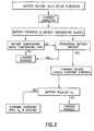
- the rising voltage of the charger is sensed and enables the start-up module 6.
- a signal is generated by the temperature sensitive resistor 8 relative to the temperature of the battery. This signal is compared to a predetermined limit set in the comparator 10. If the battery temperature exceeds the limit, then charging will be aborted.
- a signal indicative of the proper connection of battery pack 3 is generated at resistor 9 and if the signal complies with the predetermined criteria of comparator 11, Phase 1 of the start-up charging cycle is initiated. In phase 1, the charger current is limited to 100mA.
- the start-up module 6 passes control to the energy management module 5, and phase 2 of the start-up charging cycle will begin.
- the charging current is limited to 300mA.
- the charging cycle is monitored by a timer which is enabled at the start of phase 2. After the expiration of a predetermined period, the battery voltage is checked. At this point the battery voltage should be sufficient to power the MCU 2 (V R ). If has not charged to V R , then the charger is shut down. Once V R is attained, during this period, the MCU will assume control of the charging in a conventional manner.
- the present invention includes any novel feature or combination of features disclosed herein either explicitly or any generalisation thereof irrespective of whether or not it relates to the claimed invention or mitigates any or all of the problems addressed.
Landscapes
- Engineering & Computer Science (AREA)
- Power Engineering (AREA)
- Charge And Discharge Circuits For Batteries Or The Like (AREA)
- Secondary Cells (AREA)
- Mobile Radio Communication Systems (AREA)
Abstract
Description
Claims (11)
- A battery charging system for a cellular phone, said cellular phone having a controller constructed to operate the battery charging system when enabled, said controller having a predetermined minimum operating voltage threshold, said charging system comprising:wherein the start-up module enables the supply of a limited current to the battery when the temperature of the battery is below the preset limit and disables the charger when the temperature of the battery exceeds said preset limit.a charger for connection to the cellular phone to provide a charging current to the battery when the battery is depleted;an energy management module connected to control a start-up operation of the charger when the battery voltage falls below said operational threshold of the controller;a start-up charging module connected within the energy management module to control an initial phase of the start-up operation of the charger, said start-up charging module further comprising:a first sensor connected in operative association with the battery to sense the temperature of the battery and generate a signal relative thereto;a first comparator connected to receive the signal from the first sensor and compare said signal to a preset temperature limit;
- A battery charging system for a cellular phone, said cellular phone having a controller constructed to operate the battery charging system when enabled, said controller having a predetermined minimum operating voltage threshold, said charging system as described in claim 1 further comprising:wherein the start-up module enables the supply of a limited current to the battery, when said preset conditions are present, and disables the charger, when said preset conditions are not met.a second sensor connected in operative association with the battery to sense the presence thereof and generate a signal indicative of said presence; anda second comparator connected to receive the signal from the second sensor and compare said signal to preset conditions;
- A battery charging system for a cellular phone, said cellular phone having a controller constructed to operate the battery charging system when enabled, said controller having a predetermined minimum operating voltage threshold, said charging system as described in claim 1 or 2 wherein the start-up module is powered by the voltage output of the charger.
- A battery charging system for a cellular phone, said cellular phone having a controller constructed to operate the battery charging system when enabled, said controller having a predetermined minimum operating voltage threshold, said charging system, as described in claim 1, 2 or 3, wherein said start-up operation is in two phases including an initial phase in which the charging current is limited to an initial value and a second phase wherein said charging current is limited to a second larger value, and further wherein the initial phase is controlled by the start-up module and the second phase is controlled by the energy management module and wherein the second phase is initiated upon the battery voltage attaining a first predetermined value.
- A battery charging system for a cellular phone, said cellular phone having a controller constructed to operate the battery charging system when enabled, said controller having a predetermined minimum operating voltage threshold, said charging system as described in claim 4 wherein said energy management module further comprises a timer which is enabled with the initiation of the second phase of said start-up operation begins, and wherein said energy management module shuts down the charging cycle if, upon the expiration of a predetermined period of the timer, a preset battery voltage is not attained.
- In a battery charging system for a cellular telephone having a charger, a main controller for operating said charger, said main controller having a predetermined minimum operating voltage threshold, and an energy management module for operating the charger when said operating voltage threshold is not available, a method for replenishing the voltage level when the battery voltage falls below said threshold, comprising the steps of:connecting the cellular telephone to the charger;sensing the voltage level of the battery and comparing said voltage to said operational voltage threshold;enabling the energy management module when said battery voltage level is below said voltage threshold, wherein said module initiates a start-up charging cycle with a limited charging current;sensing the temperature of the battery and generating a signal relative thereto;comparing the temperature signal with a predetermined maximum value;enabling the supply of a limited current to the battery when the temperature of the battery is below the preset limit; anddisabling the charger if said temperature signal exceeds the predetermined maximum.
- In a battery charging system for a cellular telephone having a charger, a main controller for operating said charger, said main controller having a predetermined minimum operating voltage threshold, and an energy management module for operating the charger when said operating voltage threshold is not available, a method for replenishing the voltage level when the battery voltage falls below said threshold, as described in claim 6, further comprising the steps of:sensing the presence of the battery and generating a signal relative thereto;comparing the presence signal to a predetermined value;enabling the supply of a limited current to the battery when said preset conditions are present; anddisabling the charger if the predetermined condition is not met.
- In a battery charging system for a cellular telephone having a charger, a main controller for operating said charger, said main controller having a predetermined minimum operating voltage threshold, and an energy management module for operating the charger when said operating voltage threshold is not available, a method for replenishing the voltage level when the battery voltage falls below said threshold, as described in claim 6 or 7, further comprising the step of powering the sensing and comparing steps from the output of the charger.
- In a battery charging system for a cellular telephone having a charger, a main controller for operating said charger, said main controller having a predetermined minimum operating voltage threshold, and an energy management module for operating the charger when said operating voltage threshold is not available, a method for replenishing the voltage level when the battery voltage falls below said threshold, as described in claim 6, 7 or 8, wherein said start-up operation is in two phases including an initial phase in which the charging current is limited to an initial value and a second phase wherein said charging current is limited to a second larger value, and further wherein the initial phase is controlled by the start-up module and the second phase is controlled by the energy management module and wherein the second phase is initiated upon the battery voltage attaining a first predetermined value.
- In a battery charging system for a cellular telephone having a charger, a main controller for operating said charger, said main controller having a predetermined minimum operating voltage threshold, and an energy management module for operating the charger when said operating voltage threshold is not available, a method for replenishing the voltage level when the battery voltage falls below said threshold, as described in claim 9, further comprising the steps of:setting a predetermined target charge for the start-up operation's second phase;timing the second phase of start-up operation; andsetting a time limit for reaching the target charge in the second phase; anddisabling the start-up operations in the event that the target charge is not attained during the preset time limit.
- Apparatus for controlling the recharging of a battery-powered device, the apparatus comprising first and second units operable to control the supply of a charging current from an external charger, such that the first unit is operable if a supply voltage from the battery exceeds a threshold, and the second unit is operable if the supply voltage from the battery is below the threshold, the second unit being arranged to:sense the temperature of the battery;initiate a charging cycle with a predetermined charging current; anddisable the charging cycle if the temperature of the battery reaches a predetermined limit.
Applications Claiming Priority (2)
| Application Number | Priority Date | Filing Date | Title |
|---|---|---|---|
| US09/372,439 US6100672A (en) | 1999-08-11 | 1999-08-11 | Start up charging control |
| US372439 | 1999-08-11 |
Publications (2)
| Publication Number | Publication Date |
|---|---|
| EP1076396A2 true EP1076396A2 (en) | 2001-02-14 |
| EP1076396A3 EP1076396A3 (en) | 2002-01-09 |
Family
ID=23468121
Family Applications (1)
| Application Number | Title | Priority Date | Filing Date |
|---|---|---|---|
| EP00306869A Withdrawn EP1076396A3 (en) | 1999-08-11 | 2000-08-10 | Start up control of a battery charger |
Country Status (3)
| Country | Link |
|---|---|
| US (1) | US6100672A (en) |
| EP (1) | EP1076396A3 (en) |
| JP (1) | JP2001103674A (en) |
Families Citing this family (10)
| Publication number | Priority date | Publication date | Assignee | Title |
|---|---|---|---|---|
| US6697645B1 (en) * | 2000-08-17 | 2004-02-24 | Motorola, Inc. | Phone with ambient temperature sensor and display |
| US20020158861A1 (en) * | 2001-04-25 | 2002-10-31 | Borisav Maksimovic | Method and apparatus for performing automatic display contrast adjustment in a battery powered device |
| JP3928643B2 (en) * | 2005-01-26 | 2007-06-13 | ブラザー工業株式会社 | Telephone |
| US20090267570A1 (en) * | 2008-04-28 | 2009-10-29 | Nokia Corporation | Apparatus for providing boot-up capability signals and associated methods |
| KR101249840B1 (en) | 2008-07-31 | 2013-04-05 | 삼성전자주식회사 | Computer system to which battery pack is attachable and system body thereof |
| US8374012B2 (en) * | 2010-06-10 | 2013-02-12 | Carefusion 303, Inc. | Phase-controlled uninterruptible power supply |
| US9436479B2 (en) | 2011-01-17 | 2016-09-06 | Qualcomm Incorporated | Booting a mobile electronic device with a low battery based on a dynamic boot threshold |
| US10175271B2 (en) * | 2012-12-31 | 2019-01-08 | Silicon Laboratories Inc. | Apparatus for differencing comparator and associated methods |
| KR102401578B1 (en) * | 2015-09-03 | 2022-05-24 | 삼성전자주식회사 | Method for inspecting auxiliary power supply and electronic device adopting the same |
| KR102301102B1 (en) * | 2017-08-25 | 2021-09-10 | 광동 오포 모바일 텔레커뮤니케이션즈 코포레이션 리미티드 | Terminal device and its battery safety monitoring method |
Family Cites Families (8)
| Publication number | Priority date | Publication date | Assignee | Title |
|---|---|---|---|---|
| JPH0515077A (en) * | 1990-11-27 | 1993-01-22 | Furukawa Battery Co Ltd:The | Charging circuit |
| FI109567B (en) * | 1991-02-25 | 2002-08-30 | Nokia Corp | Quick charging device |
| FI96465C (en) * | 1994-05-16 | 1996-06-25 | Nokia Mobile Phones Ltd | A method and coupling arrangement for identifying a rechargeable battery charger to a portable device |
| FI99176C (en) * | 1994-11-11 | 1997-10-10 | Nokia Mobile Phones Ltd | Procedure for fast charging of different types of batteries |
| FI112730B (en) * | 1995-09-05 | 2003-12-31 | Nokia Corp | Determination of the accumulator voltage between the charge and the charging device for accumulators |
| DE19609140A1 (en) * | 1996-03-08 | 1997-09-18 | Nokia Mobile Phones Ltd | Charging circuit |
| US5705915A (en) * | 1997-03-03 | 1998-01-06 | Motorola, Inc. | Method for charging a battery |
| US6037747A (en) * | 1997-10-15 | 2000-03-14 | Lucent Technologies Inc. | Mode selection circuit for a battery and method of operation thereof |
-
1999
- 1999-08-11 US US09/372,439 patent/US6100672A/en not_active Expired - Lifetime
-
2000
- 2000-08-07 JP JP2000244027A patent/JP2001103674A/en active Pending
- 2000-08-10 EP EP00306869A patent/EP1076396A3/en not_active Withdrawn
Also Published As
| Publication number | Publication date |
|---|---|
| JP2001103674A (en) | 2001-04-13 |
| US6100672A (en) | 2000-08-08 |
| EP1076396A3 (en) | 2002-01-09 |
Similar Documents
| Publication | Publication Date | Title |
|---|---|---|
| TWI277268B (en) | Battery pack, battery protection processing apparatus, and startup control method of the battery protection processing apparatus | |
| JP5351523B2 (en) | Power surge filtering in protection against overcurrent and short circuit | |
| JP3777022B2 (en) | Battery charger | |
| US5990664A (en) | Process and apparatus for modulating terminal voltage of battery | |
| JP2906422B2 (en) | Charging device | |
| JP2861879B2 (en) | Battery pack | |
| JP5361353B2 (en) | Charge control method and charge control device for secondary battery | |
| US7548041B2 (en) | Power management circuit and methodology for battery-powered systems | |
| US6100672A (en) | Start up charging control | |
| JPH097641A (en) | Charging method of secondary battery | |
| KR100584324B1 (en) | Power control device of composite terminal | |
| CN216720949U (en) | Charge-discharge protection device and starting power supply equipment | |
| KR20220170513A (en) | BMS wake-up device by charge detection | |
| JP4565771B2 (en) | Battery charge control device | |
| CN100416976C (en) | charging equipment | |
| JPH08103032A (en) | Rechargeable battery charging method | |
| JPH08308129A (en) | Charger | |
| US6304063B2 (en) | Lithium ion battery unit adapted to be charged by an alkaline charger | |
| JP3096319B2 (en) | Quick charger | |
| JP2001169471A (en) | Secondary battery device | |
| JP3208786B2 (en) | Battery charger | |
| EP2061129A1 (en) | Battery power management method and apparatus for controlling high-temperature condition | |
| JP3402757B2 (en) | Secondary battery charging method and secondary battery charging device | |
| KR920002687B1 (en) | Ni-Cad Battery Fast Charging Circuit | |
| JPH09130983A (en) | Battery charge control device |
Legal Events
| Date | Code | Title | Description |
|---|---|---|---|
| PUAI | Public reference made under article 153(3) epc to a published international application that has entered the european phase |
Free format text: ORIGINAL CODE: 0009012 |
|
| AK | Designated contracting states |
Kind code of ref document: A2 Designated state(s): AT BE CH CY DE DK ES FI FR GB GR IE IT LI LU MC NL PT SE Kind code of ref document: A2 Designated state(s): DE FR GB IT |
|
| AX | Request for extension of the european patent |
Free format text: AL;LT;LV;MK;RO;SI |
|
| PUAL | Search report despatched |
Free format text: ORIGINAL CODE: 0009013 |
|
| AK | Designated contracting states |
Kind code of ref document: A3 Designated state(s): AT BE CH CY DE DK ES FI FR GB GR IE IT LI LU MC NL PT SE |
|
| AX | Request for extension of the european patent |
Free format text: AL;LT;LV;MK;RO;SI |
|
| RAP1 | Party data changed (applicant data changed or rights of an application transferred) |
Owner name: NOKIA CORPORATION |
|
| 17P | Request for examination filed |
Effective date: 20020709 |
|
| AKX | Designation fees paid |
Free format text: DE FR GB IT |
|
| 17Q | First examination report despatched |
Effective date: 20030214 |
|
| STAA | Information on the status of an ep patent application or granted ep patent |
Free format text: STATUS: THE APPLICATION IS DEEMED TO BE WITHDRAWN |
|
| 18D | Application deemed to be withdrawn |
Effective date: 20030625 |