The present invention relates to a power supply apparatus and a power supply
controlling method for use with a multi-function type electronic device that operates
as a portable telephone, a GPS (Global Positioning System), and a music program
reproducing player.
There are many types of portable information terminal units referred to as
PDA (Personal Digital Assistant) units. As PDA units, cellular type portable
telephone units, simple type portable telephone units (for example, PHS: Personal
Handy phone System units), portable personal computers and electronic handy note
books are known. When a portable telephone is connected to a portable personal
computer, an electronic mail can be sent and received. As other examples of PDA
units, GPS terminal units and portable music program reproducing players are
known. A GPS terminal unit detects signals from satellites and displays the current
position of the unit on its display. A portable music program reproducing unit
downloads a music program to a record memory that is attachable thereto and
detachable therefrom and
reproduces the downloaded music program.
As such various types of PDA units are
becoming common, there may be many situations of which
the user should carry them at a time.
To solve such inconvenient situations, multi-function
type PDA units have been proposed. For
example, a multi-function type portable information
terminal unit having a portable telephone function (a
conventional cellular telephone function or a PHS
function), a GPS function for locating the current
position, and a music program reproducing function for
reproducing a downloaded music program has been
proposed. With such a multi-function type portable
information terminal unit, the user can conveniently
and easily use such functions.
However, such a multi-function type portable
information terminal unit has only one battery that
supplies an electric power to a plurality of functional
portions. Thus, when the user uses one function of the
unit, if the power of the battery is consumed, the user
cannot use another function.
For example, after the user has enjoyed a
music program with the player function of the multiple-function
type portable information terminal unit that
has the telephone function, the GPS function, and the
player function, when the user wants to use the
telephone function, if the battery has been exhausted,
the user cannot use the telephone function because sufficient power cannot be
supplied. Thus, unless the user always checks for the remaining battery capacity, he
or she may not use his or her desired function.
Therefore, an object of the present invention is to provide a power supply
apparatus and a power supply controlling method for use with an electronic device
that allow battery capacities to be separately assigned to a plurality of functions of
the device.
Another object of the present invention is to provide a power supply
apparatus and a power supply controlling method for use with an electronic device
that allow battery capacities to be assigned to a plurality of functions corresponding
to the frequencies in use and their current consumption.
A first aspect of the present invention is a power supply apparatus for
supplying a power of a battery to a plurality of functional blocks of an electronic
device that operate therewith, comprising a battery capacity assigning means for
assigning battery capacities to the plurality of functional blocks, and a battery
capacity managing means for managing the battery capacities of the plurality of
functional blocks that operate corresponding to the battery capacities assigned to the
plurality of functional
blocks.
A second aspect of the present invention is a power supply controlling
method for supplying a power of a battery to a plurality of functional blocks of an
electronic device that operate therewith, comprising the steps of (a) assigning battery
capacities to the plurality of functional blocks, and (b) managing the battery
capacities of the plurality of functional blocks that operate corresponding to the
battery capacities assigned to the plurality of functional blocks.
According to the present invention, battery capacities can be freely assigned
to a plurality of functions of the unit. In addition, since the battery capacities
assigned to the individual functions are always supervised and a message
corresponding to a remaining battery capacity is issued to the user, all the capacity of
the battery can be more effectively and rationally used. When a battery capacity
assigned to one function remains, it can be assigned to another function. Thus, all
the capacity of the battery can be effectively used. In addition, since a battery
capacity can be freely assigned to a function designated by the user, the operability of
the unit is improved.
The present invention will be further described by way of example with
reference to the accompanying drawings, in which:-
Next, with reference to the accompanying drawings, an embodiment of the
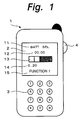
present invention will be described. Fig. 1 is a schematic diagram showing an
example of the structure of a portable information terminal unit according to the
present invention. The portable information terminal unit 1 is a multi-function type
portable information terminal unit having a GPS function, a player function for
reproducing a music program, and a portable telephone function.
The portable information terminal unit 1 has a displaying portion 2. The
displaying portion 2 displays various types of data corresponding to each function.
For example, when the portable information terminal unit 1 is used as a portable
telephone unit, the displaying portion 2 displays a telephone number, a message, and
so forth. When the portable information terminal unit 1 is used as a GPS unit, the
displaying portion 2 displays the latitude and the longitude of
the current position of the unit and so forth. When
the portable information terminal unit 1 is used as a
music program reproducing player unit, the displaying
portion 2 displays the program tile and the
reproduction time period of a music program that is
being reproduced and so forth.
The portable information terminal unit 1 has
a keyboard 3. The keyboard 3 is composed of 10 numeric
keys "0" to "9" and symbol keys "*" and "#". When the
portable information terminal unit 1 is used as a
portale telephone unit, the keyboard 3 is used to input
a telephone number and so forth. When the portable
information terminal unit 1 is used as a music program
reproducing player unit, the keyboard 3 is used to
input the title of a music program that user wants to
reproduce. In addition, as will be described later,
the keyboard 3 is used to assign battery capacities to
individual functions.
A selection dial 4 (also referred to as jog
dial) is disposed at an upper side position of the
portable information terminal unit 1. When the user
turns and presses the selection dial 4 at predetermined
positions, he or she can designate various modes and
operations of the portable information terminal unit 1.
The user can designate the portable
information terminal unit 1 as a GPS function (function
"1"), a player function for reproducing a music program
(function "2"), and a portale telephone unit (function
"3"). To accomplish these functions, the portable
information terminal unit 1 has a GPS receiver portion
5, a player portion 6, and a telephone portion 7 as
shown in Fig. 2.
The GPS receiver portion 5 generates GPS data
with a GPS signal received through an antenna and
calculates the current position of the portable
information terminal unit 1 corresponding to the
generated GPS data. In reality, the GPS receiver
portion 5 obtains the distance to each of three or more
GPS satellites corresponding to the transmission delay
time differences of radio wave signals received
therefrom and detects the intersection of each
spherical surface with the center of each GPS satellite
as the absolute position of the user. In such a
manner, the GPS data is formed. Corresponding to the
GPS data, the current position of the portable
information terminal unit 1 is calculated by the
calculating process.
The player portion 6 has a record medium such
as a semiconductor memory that is attachable thereto
and detachable therefrom. The player portion 6 reads
music program data from the record medium, decodes the
music program data (that has been compression-encoded
corresponding to ATRAC method or the like), and
generates a reproduced audio signal. The reproduced
audio signal is amplified and supplied to a head set or
the like. With the head set, the music program is
reproduced.
The telephone portion 7 performs a receiving
process and a transmitting process in parallel. In the
receiving process, the telephone portion 7 performs a
frequency converting process and an amplifying process
for an RF signal received through the antenna,
generates a base-band signal, performs a demodulating
process for the received signal, and generates an audio
signal. The received audio signal is amplified and
supplied to a speaker. In the transmitting process,
the telephone portion 7 performs a compression-encoding
process for a transmission audio signal received from a
microphone, generates audio data, combines the audio
data and predetermined control data, obtains
transmission data, modulates the transmission data, and
generates a base-band transmission signal. Thereafter,
the telephone portion 7 performs a frequency converting
process and an amplifying process for the obtained
base-band signal, generates an RF signal, and transmits
the generated RF signal through the antenna.
With the selection dial 4 shown in Fig. 1,
the user can designate the GPS function, the player
function, or the portable telephone function. When the
user designates the GPS function, the GPS receiver
portion 5 shown in Fig. 2 operates. Thus, with the GPS
function, the current position of the portable
information terminal unit 1 can be detected. When the
user designates the player function, the player portion
6 operates. Thus, with the portable information
terminal unit 1, the user can enjoy a reproduced music
program. When the user designates the telephone
function, the telephone portion 7 operates. Thus, with
the portable information terminal unit 1, the user can
send and receive a call to/from a remote party.
Since the portable information terminal unit
1 has a plurality of functions, the user can easily and
conveniently use them. In addition, the portable
information terminal unit 1 has one battery 8 that
supplies a power to the GPS receiver portion 5, the
player portion 6, and the telephone portion 7. The
battery 8 is a secondary battery such as a nickel
cadmium battery, a nickel hydrogen battery, or a
lithium ion battery.
Since only one battery 8 supplies a power to
the GPS receiver portion 5, the player portion 6, and
the telephone portion 7, if the battery is exhausted by
one function of the portable information terminal unit
1, the user cannot use another function.
To solve such a problem, the portable
information terminal unit 1 according to the present
invention has a power supply controlling portion 9.
With the power supply controlling portion 9, battery
capacities can be assigned to the individual functions.
The power supply controlling portion 9 comprises a
capacity detecting portion 21, a supplying portion 22,
a capacity assigning portion 23, and a supervising
portion 24. The capacity detecting portion 21 detects
the capacity of the battery 8. The supplying portion
22 supplies the power to the individual functional
portions that are the GPS receiver portion 5, the
player portion 6, the telephone portion 7, and so
forth. The supervising portion 24 supervises the
capacity of the battery 8. As will be described later,
the structural portions of the power supply controlling
portion 9 can be composed by software. With the power
supply controlling portion 9, desired battery
capacities can be assigned to the individual functional
portions as if they have independent batteries.
In other words, when each function is used,
if the consumed battery capacity thereof reaches the
assigned battery capacity thereof, an alarm portion 10
generates an alarm. Alternatively, the displaying
portion 2 displays an alarm message. When the consumed
battery capacity of the functional portion exceeds the
assigned battery capacity thereof, the power supply to
the functional portion is stopped. Thus, since the
battery capacities assigned to the other functional
portions are not exhausted, when the user wants to use
another function, he or she can use it. When the power
capacities assigned to the other functions are not
exhausted, the user can assign them to his or her
desired functional portion. Thus, the battery capacity
can be effectively used.
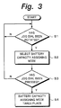
Fig. 3 is a flow chart showing an operation
for assigning battery capacities to the individual
functions. In Fig. 3, when the selection dial (jog
dial) 4 is operated (at step S1), a predetermined mode
is selected corresponding to the rotation of the jog
dial 4 (at step S2). With the jog dial 4, a battery
capacity assigning mode is selected. When the job dial
4 is pressed (at step S3), a battery capacity assigning
mode takes place (at step S4).
In the battery capacity assigning mode, as
shown in Fig. 1, a mode name that represents that the
current mode is "battery capacity assigning mode" is
displayed in an area 11 on the top line of the
displaying portion 2. A remaining time period is
displayed in an area 12. A battery capacity bar is
displayed in an area 13. The ratio of a battery
capacity assigned to the current function is displayed
in an area 14. The current function name is displayed
in an area 15.
The battery capacity bar shown in the area 13
represents the battery capacity assigned to the
selected function. As shown in Fig. 4, the battery
capacity bar has an indication bar A1, an indication
bar A2, and an indication bar A3. The indication bar
A1 represents a non-assigned state of the battery
capacity. The indication bar A2 represents a battery
capacity assigned to the selected function. The
indication bar A3 represents a battery capacity
assigned to the other functions.
When the battery capacity assigning mode is
selected, as shown in Fig. 4A, the battery capacity bar
for assigning a battery capacity to the function "1" is
displayed. Initially, as shown in Fig. 4A, no battery
capacities have been assigned to other functions.
Thus, the battery capacity bar has only the indication
bar A1 that represents the non-assigned state of the
battery capacity.
When an increase button (in this example, the
"#" button) is pressed, as shown in Fig. 4B, the
battery capacity assigned to the function "1"
increases. Thus, the indication bar A2 that represents
the battery capacity assigned to the function "1"
becomes long. On the other hand, when a decrease
button (in this example, the "*" button) is pressed,
the battery capacity assigned to the function "1"
decreases. Thus, the indication bar A2 that represents
the battery capacity assigned to the function "1"
becomes short. With reference to the battery capacity
bar, the user can visually know the battery capacity
assigned to the function "1".
After the battery capacity has been assigned to
the function "1", a set key (in this example, the "8"
key) is pressed. When the set key is pressed, as shown
in Fig. 5A, a battery capacity bar for assigning a
battery capacity to the function "2" is displayed.
At this point, since a battery capacity has
been assigned to the function "1", all the capacity of
the battery 8 cannot be assigned to the function "2".
In addition, as shown in Fig. 5A, the battery capacity
bar has the indication bar A3 that represents the
battery capacity assigned to another function (in this
example, the function "1").
When the increase button is pressed, as shown
in Fig. 5B, the battery capacity assigned to the
function "2" increases. Thus, the indication bar A2
that represents the battery capacity assigned to the
function "2" becomes long. On the other hand, when the
decrease button is pressed, the battery capacity
assigned to the function "2" decreases. Thus, the
indication bar A2 that represents the battery capacity
assigned to the function "2" becomes short.
After a battery capacity has been assigned to
the function "2", the set key is pressed. When the set
key is pressed, as shown in Fig. 6A, a battery capacity
bar for assigning a battery power to the function "3"
is displayed.
At this point, since battery capacities have
been assigned to the functions "1" and "2", all the
capacity of the battery 8 cannot be assigned to the
function "3". As shown in Fig. 6A, the battery
capacity bar has the indication bar A3 that represents
battery capacities assigned to the other functions (in
this example, the functions "1" and "2").
When the increase button is pressed, as shown
in Fig. 6B, the battery capacity assigned to the
function "3" increases. Thus, the indication bar A2
that represents the battery capacity assigned to the
function "3" becomes long. On the other hand, when the
decrease button is pressed, the battery capacity
assigned to the function "3" decreases. Thus, the
indication bar A2 that represents the battery capacity
assigned to the function "3" becomes short.
In such a manner, the capacity of one battery
can be assigned to a plurality of functions. In other
words, as shown in Fig. 7A, assuming that there is a
battery with a battery capacity of M, as shown in Fig.
7B, for example, 20 %, 30 %, and 50 % of the capacity
of the battery can be assigned to the function "1", the
function "2", and the function "3", respectively. The
assigned battery capacities are supervised. The user
is notified of the remaining capacities of the battery
capacities assigned to the functions. Thus, all the
capacity of the battery 8 can be more effectively and
rationally used.
Fig. 8 is a flow chart showing a process for
designating the battery capacity assigning mode. In
this example, the following registers are used.
- Total battery capacity register: a
register for storing the value corresponding to the
total capacity of the battery.
- Reserved battery capacity register: a
register for storing the value corresponding to battery
capacities reserved for other functions.
- Function "n" assigned battery capacity
register: a register for storing the value
corresponding to a time period equivalent to a battery
capacity assigned to the function "n".
When the functional portion corresponding to
the function "n" operates, the MSB (Most Significant
Bit) of the function "n" assigned battery capacity
register is "1". In other words, when the GPS receiver
portion 5 operates, the MSB of the function "1"
assigned battery capacity register is "1". When the
player portion 6 operates, the MSB of the function "2"
assigned battery capacity register is "1". When the
telephone portion 5 operates, the MSB of the function
"3" assigned battery capacity register is "1".
In addition, the current consumption per unit
time period of each function is pre-obtained. The
current consumption per unit time period of each
function is denoted by Pn. In other words, the curent
consumption per unit time period Δt of the GPS receiver
portion 5 that accomplishes the function "1" is P1.
The curent consumption per unit time period Δt of the
player portion 6 that accomplishes the function "2" is
P2. The curent consumption per unit time period Δt of
the telephone portion 7 that accomplishes the function
"3" is P3.
In Fig. 8, it is determined whether or not
the battery capacity assigning mode has taken place (at
step S11). When the determined result at step S11 is
Yes (namely, the battery capacity assigning mode has
taken place), the value corresponding to all the
capacity of the battery is stored to the total battery
capacity register (at step S12).
All the capacity of the battery is detected
by for example detecting a drop of a terminal voltage
due to a variation of the internal resistance of the
battery or a current due to a variation of a terminal
voltage. The battery capacity may be detected in
various manners. The optimum detecting method for
detecting the battery capacity depends on the type of
the battery for use. According to the present
invention, the detecting method of the battery capacity
is not limited.
After the value corresponding to all the
capacity of the battery has been stored, the function
number "n" is initialized to "1" (at step S13).
Thereafter, an indication that represents that the
function "1" has been designated is displayed on the
displaying portion 2 (at step S14). At this point, the
power capacity bar as shown in Fig. 4A is displayed.
Thereafter, the battery capacity of the function "1" is
assigned.
Thereafter, it is determined whether or not
the assigning value increase button ("#" key) has been
pressed (at step S15). When the determined result at
step S15 is No (namely, the assigning value increase
button has not been pressed), it is determined whether
or not the assigning value decrease button ("*" key)
has been pressed (at step S16).
When the determined result at step S15 is Yes
(namely, the assigning value increase button has been
pressed), it is determined whether or not there is a
remaining capacity in the battery (at step S17). The
remaining battery capacity is obtained by subtracting
the value stored in the reserved battery capacity
register from the value stored in the total battery
capacity register. When the battery does not have a
remaining battery capacity, the flow returns to step
S14. When the determined result at step S17 is Yes
(namely, the battery has a remaining battery capacity),
the value stored in the function "1" assigned battery
capacity register increments by "1" per step. In this
example, one step is equivalent to a unit time period
Δt. The value stored in the function "1" assigned
battery capacity register increments corresponding to
the number of times of the operation of the assigning
value increase button and the time period for which the
button is pressed.
After the value stored in the function "1"
assigned battery capacity register increments by "1"
per step, the value stored in the reserved battery
capacity register increments by (Pn x Δt) per step (at
step S19). In other words, the time period for the
battery capacity used for the function "n" is stored to
the function "n" assigned battery capacity register in
the unit time period Δt per step. Since the current
consumption in the unit time period Δt of the function
"n" is Pn, the battery capacity to convert the value of
the time period into the value of the battery capacity,
the current consumption Pn is multiplied by Δt. Thus,
the value stored in the reserved battery capacity
register increments by (Pn x Δt) per step. The battery
capacity equivalent to the time period corresponding to
the value stored in the function "n" assigned battery
capacity register is stored to the reserved battery
capacity register.
When the determined result at step S16 is Yes
(namely, the assigning value decrease button has been
pressed), it is determined whether or not the value
stored in the function "1" assigned battery capacity
register is "0" (at step S20). When the determined
result at step S20 is Yes (namely, the value stored in
the function "1" assigned battery capacity register is
"0"), since the battery capacity cannot be decreased,
the flow returns to step S14. When the determined
result at step S20 is No (namely, the value stored in
the function "1" assigned battery capacity register is
not "0"), the value stored in the function "1" assigned
battery capacity register decrements by "1" per step
(at step S21). After the value stored in the function
"1" assigned battery capacity register has decremented
by "1" per step, the value stored in the reserved
battery capacity register decrements by (Pn x Δt) per
step (at step S22).
When the determined result at step S15 is Yes
(namely, the assigning value increase button has been
pressed), the value stored in the function "1" assigned
battery capacity register increments by "1" per step.
Thereafter, when the determined result at step S16 is
Yes (namely, the assigning value increase button has
been pressed), the value stored in the function "1"
assigned battery capacity register decrements by "1"
per step. Thus, the time period equivalent to the
battery capacity assigned to the function "1" increases
or decreases. As a result, the battery capacity has
been assigned to the function "1". At steps S19 and
S22, the value corresponding to the battery capacity
equivalent to the time period of the battery capacity
assigned to the function "1" is stored to the reserved
battery capacity register.
After the battery capacity has been assigned
to the function "1" at step S19 or S22, it is
determined whether or not a battery capacity is
assigned to the next function (function "2") (at step
S23). When the determined result at step S23 is Yes
(namely, a battery capacity is assigned to the next
function), the function number n increments by "1" (at
step S24). Thereafter, the flow returns to step S14.
When the determined result at step S23 is No
(namely, a battery capacity is not assigned to the next
function), it is determined whether or not the storage
capacity assigning mode is completed (at step S25).
When the determined result at step S25 is No (namely,
the storage capacity assigning mode is not completed),
the flow returns to step S14.
When the determined result at step S23 is Yes
(namely, a battery capacity is assigned to the next
function), the flow advances to step S24. At step S24,
the function number n increments by "1". Since the
current function number is "1", the function number
becomes "2". As described above, in the loop from step
S14 to step S22, the time period equivalent to the
battery capacity for the function "2" is assigned. The
total capacity of the battery capacity assigned to the
function "2" and the battery capacity assigned to the
function "1" is stored to the reserved battery capacity
register.
Thereafter, the similar process is repeated.
The values corresponding to the time periods equivalent
to the battery capacities assigned to the function "1",
the function "2", and the function "3" are stored to
the function "n" assigned battery capacity registers.
In addition, the value corresponding to the total
battery capacity assigned to the function "1", the
function "2", and the function "3" is stored to the
reserved battery capacity register.
After battery capacities have been assigned
to all the functions, the determined results at steps
S23 and S25 become No. Thus, a battery capacity is not
assigned to the next function and the battery capacity
assigning process is completed.
After battery capacities have been assigned
to all the functions, the value corresponding to the
total battery capacity is stored to the total battery
capacity register. The value corresponding to the
reserved battery capacity is stored to the reserved
battery capacity register. The values corresponding to
the time periods equivalent to the battery capacities
assigned to the functions are stored to the function
"n" assigned battery capacity registers.
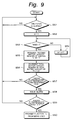
Fig. 9 shows a process performed when the
unit is used. In Fig. 9, it is determined whether or
not a predetermined time period At has elapsed (at step
S51). When the determined result at step S51 is Yes
(namely, a predetermined time period Δt has elapsed),
the function number "n" is initialized to "1" (at step
S52). Thereafter, it is determined whether or not the
MSB of the function "n" assigned battery capacity
register is "1" (at step S53). When the determined
result at step S53 is No (namely, the MSB of the
function "n" assigned battery capacity register is not
"1"), the function number "n" increments (at step S54).
Thereafter, the flow returns to step S53.
As was descried above, when the function
corresponding to the function "n" assigned battery
capacity register operates, the MSB thereof is "1". In
other words, when the GPS receiver portion 5 operates,
the MSB OF the function "1" assigned battery capacity
register is "1". When the player portion 6 operates,
the MSB OF the function "2" assigned battery capacity
register is "1". When the GPS receiver portion 5
operates, the MSB OF the function "3" assigned battery
capacity register is "1". Thus, since the "n" function
assigned battery capacity register whose MSB is "1" is
detected at step S53, the function corresponding
thereto can be detected.
After the function "n" assigned battery
capacity register whose MSB is "1" has been detected at
step 553, the value stored in the function "n" assigned
battery capacity register decrements by "1" (at step
S55). Thereafter, the value stored in the total
battery capacity register decrements by "Pn x Δt" (at
step S56). The value stored in the total battery
capacity register decrements by "Pn x Δt" because a
time period as a value stored in the function "n"
assigned battery capacity register should be converted
into a battery capacity as a value stored in the total
battery capacity register.
Thereafter, it is determined whether the
value stored in the function "n" assigned battery
capacity register does not exceed a predetermined value
(at step S57). When the determined result at step S57
is No (namely, the value stored in the function "n"
assigned battery capacity register exceeds the
predetermined value), the flow returns to step S51.
In such a manner, the value stored in the
function "n" assigned battery capacity register
decrements by "1" at intervals of a predetermined time
period Δt at step S55. The function "n" assigned
battery capacity register stores a value corresponding
to a time period equivalent to a battery capacity
assigned to the function "n". Thus, as the operation
time of the function elapses, the value stored in the
function "n" assigned battery capacity register
decreases.
When the determined result at step S57 is Yes
(namely, the value stored in the function "n" assigned
battery capacity register does not exceed the
predetermined value), an alarm that represents that the
time period equivalent to the battery capacity assigned
to the function will elapse soon is generated (at step
S58). This alarm may be generated by the speaker as an
audio alarm or displayed by the displaying unit as an
alarm message.
Thereafter, it is determined whether or not
the value stored in the function "n" assigned battery
capacity register is "0" (at step S59). When the value
stored in the function "n" assigned battery capacity
register is "0", the time period equivalent to the
battery capacity assigned to the function has elapsed.
When the determined result at step S59 is No (namely,
the value stored in the function "n" assigned battery
capacity register is not "0"), the flow returns to step
S51. When the determined result at step S59 is Yes
(namely, the value stored in the function "n" assigned
battery capacity register is "0"), the power supplied
to the functional portion corresponding to the function
"n" is stopped (at step S60).
In the above-mentioned embodiment, the
portable telephone unit having the GPS function, the
player function, and the telephone function was
described. However, it should be noted that the
present invention can be readily applied to a portable electronic unit having two or
more functions other than the above-mentioned functions.
According to the present invention, battery capacities can be freely assigned
to a plurality of functions of the unit. In addition, since the battery capacities
assigned to the individual functions are always supervised and a message
corresponding to a remaining battery capacity is issued to the user, all the capacity of
the battery can be more effectively and rationally used. When a battery capacity
assigned to one function remains, it can be assigned to another function. Thus, all
the capacity of the battery can be effectively used. In addition, since a battery
capacity can be freely assigned to a function designated by the user, the operability of
the unit is improved.