EP1076239A2 - Coating with cross-linked hydrophilic polymers - Google Patents
Coating with cross-linked hydrophilic polymers Download PDFInfo
- Publication number
- EP1076239A2 EP1076239A2 EP00116757A EP00116757A EP1076239A2 EP 1076239 A2 EP1076239 A2 EP 1076239A2 EP 00116757 A EP00116757 A EP 00116757A EP 00116757 A EP00116757 A EP 00116757A EP 1076239 A2 EP1076239 A2 EP 1076239A2
- Authority
- EP
- European Patent Office
- Prior art keywords
- capillaries
- capillary
- cross
- pva
- polymer
- Prior art date
- Legal status (The legal status is an assumption and is not a legal conclusion. Google has not performed a legal analysis and makes no representation as to the accuracy of the status listed.)
- Granted
Links
- 229920001477 hydrophilic polymer Polymers 0.000 title claims abstract description 7
- 238000000576 coating method Methods 0.000 title abstract description 26
- 239000011248 coating agent Substances 0.000 title abstract description 16
- 238000000034 method Methods 0.000 claims abstract description 47
- 229920000642 polymer Polymers 0.000 claims abstract description 25
- 239000003431 cross linking reagent Substances 0.000 claims abstract description 7
- 238000010382 chemical cross-linking Methods 0.000 claims abstract description 3
- 229920002451 polyvinyl alcohol Polymers 0.000 claims description 49
- 239000004372 Polyvinyl alcohol Substances 0.000 claims description 45
- 238000000926 separation method Methods 0.000 claims description 32
- IJGRMHOSHXDMSA-UHFFFAOYSA-N Atomic nitrogen Chemical compound N#N IJGRMHOSHXDMSA-UHFFFAOYSA-N 0.000 claims description 30
- 229910052757 nitrogen Inorganic materials 0.000 claims description 15
- 239000007789 gas Substances 0.000 claims description 14
- 150000001875 compounds Chemical class 0.000 claims description 12
- SXRSQZLOMIGNAQ-UHFFFAOYSA-N Glutaraldehyde Chemical compound O=CCCCC=O SXRSQZLOMIGNAQ-UHFFFAOYSA-N 0.000 claims description 8
- 238000001035 drying Methods 0.000 claims description 6
- 239000007788 liquid Substances 0.000 claims description 6
- XKRFYHLGVUSROY-UHFFFAOYSA-N Argon Chemical compound [Ar] XKRFYHLGVUSROY-UHFFFAOYSA-N 0.000 claims description 4
- 238000004458 analytical method Methods 0.000 claims description 4
- ZNZYKNKBJPZETN-WELNAUFTSA-N Dialdehyde 11678 Chemical compound N1C2=CC=CC=C2C2=C1[C@H](C[C@H](/C(=C/O)C(=O)OC)[C@@H](C=C)C=O)NCC2 ZNZYKNKBJPZETN-WELNAUFTSA-N 0.000 claims description 3
- 239000003153 chemical reaction reagent Substances 0.000 claims description 3
- 229910052786 argon Inorganic materials 0.000 claims description 2
- 239000001307 helium Substances 0.000 claims description 2
- 229910052734 helium Inorganic materials 0.000 claims description 2
- SWQJXJOGLNCZEY-UHFFFAOYSA-N helium atom Chemical compound [He] SWQJXJOGLNCZEY-UHFFFAOYSA-N 0.000 claims description 2
- 239000001257 hydrogen Substances 0.000 claims description 2
- 229910052739 hydrogen Inorganic materials 0.000 claims description 2
- 239000000126 substance Substances 0.000 claims description 2
- UFHFLCQGNIYNRP-UHFFFAOYSA-N Hydrogen Chemical compound [H][H] UFHFLCQGNIYNRP-UHFFFAOYSA-N 0.000 claims 1
- 150000001299 aldehydes Chemical class 0.000 claims 1
- 125000002915 carbonyl group Chemical group [*:2]C([*:1])=O 0.000 claims 1
- 239000011261 inert gas Substances 0.000 claims 1
- 150000002576 ketones Chemical class 0.000 claims 1
- 230000003100 immobilizing effect Effects 0.000 abstract 1
- 238000005251 capillar electrophoresis Methods 0.000 description 37
- VYPSYNLAJGMNEJ-UHFFFAOYSA-N Silicium dioxide Chemical compound O=[Si]=O VYPSYNLAJGMNEJ-UHFFFAOYSA-N 0.000 description 25
- 239000005350 fused silica glass Substances 0.000 description 23
- 239000000243 solution Substances 0.000 description 21
- 239000003792 electrolyte Substances 0.000 description 10
- 102000004169 proteins and genes Human genes 0.000 description 10
- 108090000623 proteins and genes Proteins 0.000 description 10
- 238000005370 electroosmosis Methods 0.000 description 9
- 230000000274 adsorptive effect Effects 0.000 description 8
- XTXRWKRVRITETP-UHFFFAOYSA-N Vinyl acetate Chemical compound CC(=O)OC=C XTXRWKRVRITETP-UHFFFAOYSA-N 0.000 description 6
- 239000007864 aqueous solution Substances 0.000 description 6
- 238000001179 sorption measurement Methods 0.000 description 6
- XLYOFNOQVPJJNP-UHFFFAOYSA-N water Substances O XLYOFNOQVPJJNP-UHFFFAOYSA-N 0.000 description 6
- 102000018832 Cytochromes Human genes 0.000 description 5
- 108010052832 Cytochromes Proteins 0.000 description 5
- 239000004971 Cross linker Substances 0.000 description 4
- 101710093543 Probable non-specific lipid-transfer protein Proteins 0.000 description 4
- 238000004519 manufacturing process Methods 0.000 description 4
- 239000003960 organic solvent Substances 0.000 description 4
- 229920006254 polymer film Polymers 0.000 description 4
- 229920002689 polyvinyl acetate Polymers 0.000 description 4
- 238000010926 purge Methods 0.000 description 4
- WEVYAHXRMPXWCK-UHFFFAOYSA-N Acetonitrile Chemical compound CC#N WEVYAHXRMPXWCK-UHFFFAOYSA-N 0.000 description 3
- IAZDPXIOMUYVGZ-UHFFFAOYSA-N Dimethylsulphoxide Chemical compound CS(C)=O IAZDPXIOMUYVGZ-UHFFFAOYSA-N 0.000 description 3
- OKKJLVBELUTLKV-UHFFFAOYSA-N Methanol Chemical compound OC OKKJLVBELUTLKV-UHFFFAOYSA-N 0.000 description 3
- 229910002808 Si–O–Si Inorganic materials 0.000 description 3
- HEMHJVSKTPXQMS-UHFFFAOYSA-M Sodium hydroxide Chemical compound [OH-].[Na+] HEMHJVSKTPXQMS-UHFFFAOYSA-M 0.000 description 3
- 230000002378 acidificating effect Effects 0.000 description 3
- 239000012491 analyte Substances 0.000 description 3
- 150000007514 bases Chemical class 0.000 description 3
- 238000006243 chemical reaction Methods 0.000 description 3
- 239000000412 dendrimer Substances 0.000 description 3
- 229920000736 dendritic polymer Polymers 0.000 description 3
- 238000002347 injection Methods 0.000 description 3
- 239000007924 injection Substances 0.000 description 3
- 239000000463 material Substances 0.000 description 3
- 239000000203 mixture Substances 0.000 description 3
- -1 proteins Chemical class 0.000 description 3
- 239000000523 sample Substances 0.000 description 3
- 102000016943 Muramidase Human genes 0.000 description 2
- 108010014251 Muramidase Proteins 0.000 description 2
- 108010062010 N-Acetylmuramoyl-L-alanine Amidase Proteins 0.000 description 2
- 239000004696 Poly ether ether ketone Substances 0.000 description 2
- 239000004809 Teflon Substances 0.000 description 2
- 229920006362 Teflon® Polymers 0.000 description 2
- 102000018690 Trypsinogen Human genes 0.000 description 2
- 108010027252 Trypsinogen Proteins 0.000 description 2
- JUPQTSLXMOCDHR-UHFFFAOYSA-N benzene-1,4-diol;bis(4-fluorophenyl)methanone Chemical compound OC1=CC=C(O)C=C1.C1=CC(F)=CC=C1C(=O)C1=CC=C(F)C=C1 JUPQTSLXMOCDHR-UHFFFAOYSA-N 0.000 description 2
- 238000001816 cooling Methods 0.000 description 2
- 230000008878 coupling Effects 0.000 description 2
- 238000010168 coupling process Methods 0.000 description 2
- 238000005859 coupling reaction Methods 0.000 description 2
- NKSJNEHGWDZZQF-UHFFFAOYSA-N ethenyl(trimethoxy)silane Chemical compound CO[Si](OC)(OC)C=C NKSJNEHGWDZZQF-UHFFFAOYSA-N 0.000 description 2
- 239000011521 glass Substances 0.000 description 2
- 230000007774 longterm Effects 0.000 description 2
- 235000010335 lysozyme Nutrition 0.000 description 2
- 239000004325 lysozyme Substances 0.000 description 2
- 229960000274 lysozyme Drugs 0.000 description 2
- 238000004949 mass spectrometry Methods 0.000 description 2
- 230000005012 migration Effects 0.000 description 2
- 238000013508 migration Methods 0.000 description 2
- 239000000178 monomer Substances 0.000 description 2
- 230000007935 neutral effect Effects 0.000 description 2
- 239000008363 phosphate buffer Substances 0.000 description 2
- 229920000058 polyacrylate Polymers 0.000 description 2
- 229920002530 polyetherether ketone Polymers 0.000 description 2
- 239000011118 polyvinyl acetate Substances 0.000 description 2
- 230000002040 relaxant effect Effects 0.000 description 2
- 238000002444 silanisation Methods 0.000 description 2
- 125000005372 silanol group Chemical group 0.000 description 2
- 238000009736 wetting Methods 0.000 description 2
- USFZMSVCRYTOJT-UHFFFAOYSA-N Ammonium acetate Chemical compound N.CC(O)=O USFZMSVCRYTOJT-UHFFFAOYSA-N 0.000 description 1
- 239000005695 Ammonium acetate Substances 0.000 description 1
- 206010022528 Interactions Diseases 0.000 description 1
- 229910019142 PO4 Inorganic materials 0.000 description 1
- 241000233805 Phoenix Species 0.000 description 1
- 239000002202 Polyethylene glycol Substances 0.000 description 1
- 239000004642 Polyimide Substances 0.000 description 1
- 102000004142 Trypsin Human genes 0.000 description 1
- 108090000631 Trypsin Proteins 0.000 description 1
- 239000002253 acid Substances 0.000 description 1
- 150000007513 acids Chemical class 0.000 description 1
- 235000019257 ammonium acetate Nutrition 0.000 description 1
- 229940043376 ammonium acetate Drugs 0.000 description 1
- 150000001450 anions Chemical class 0.000 description 1
- 229920001222 biopolymer Polymers 0.000 description 1
- 239000005352 borofloat Substances 0.000 description 1
- 238000001818 capillary gel electrophoresis Methods 0.000 description 1
- 229920006317 cationic polymer Polymers 0.000 description 1
- 238000007796 conventional method Methods 0.000 description 1
- 238000007334 copolymerization reaction Methods 0.000 description 1
- 230000001419 dependent effect Effects 0.000 description 1
- 238000001212 derivatisation Methods 0.000 description 1
- 238000001514 detection method Methods 0.000 description 1
- 230000005684 electric field Effects 0.000 description 1
- 238000001962 electrophoresis Methods 0.000 description 1
- 238000011010 flushing procedure Methods 0.000 description 1
- 238000010438 heat treatment Methods 0.000 description 1
- 125000004435 hydrogen atom Chemical class [H]* 0.000 description 1
- 230000007062 hydrolysis Effects 0.000 description 1
- 238000006460 hydrolysis reaction Methods 0.000 description 1
- 150000002433 hydrophilic molecules Chemical class 0.000 description 1
- 230000002209 hydrophobic effect Effects 0.000 description 1
- 230000003993 interaction Effects 0.000 description 1
- 238000001155 isoelectric focusing Methods 0.000 description 1
- 239000003550 marker Substances 0.000 description 1
- QSHDDOUJBYECFT-UHFFFAOYSA-N mercury Chemical compound [Hg] QSHDDOUJBYECFT-UHFFFAOYSA-N 0.000 description 1
- 229910052753 mercury Inorganic materials 0.000 description 1
- 238000003541 multi-stage reaction Methods 0.000 description 1
- 239000011255 nonaqueous electrolyte Substances 0.000 description 1
- NBIIXXVUZAFLBC-UHFFFAOYSA-K phosphate Chemical compound [O-]P([O-])([O-])=O NBIIXXVUZAFLBC-UHFFFAOYSA-K 0.000 description 1
- 239000010452 phosphate Substances 0.000 description 1
- 229920003023 plastic Polymers 0.000 description 1
- 239000004033 plastic Substances 0.000 description 1
- 229920002401 polyacrylamide Polymers 0.000 description 1
- 229920001223 polyethylene glycol Polymers 0.000 description 1
- 229920001721 polyimide Polymers 0.000 description 1
- 239000010453 quartz Substances 0.000 description 1
- 238000010526 radical polymerization reaction Methods 0.000 description 1
- 239000012487 rinsing solution Substances 0.000 description 1
- 238000007790 scraping Methods 0.000 description 1
- SCPYDCQAZCOKTP-UHFFFAOYSA-N silanol Chemical compound [SiH3]O SCPYDCQAZCOKTP-UHFFFAOYSA-N 0.000 description 1
- 239000002689 soil Substances 0.000 description 1
- 230000001629 suppression Effects 0.000 description 1
- 238000007669 thermal treatment Methods 0.000 description 1
- 239000012588 trypsin Substances 0.000 description 1
- 125000000391 vinyl group Chemical group [H]C([*])=C([H])[H] 0.000 description 1
- 229920003169 water-soluble polymer Polymers 0.000 description 1
Images


Classifications
-
- G—PHYSICS
- G01—MEASURING; TESTING
- G01N—INVESTIGATING OR ANALYSING MATERIALS BY DETERMINING THEIR CHEMICAL OR PHYSICAL PROPERTIES
- G01N27/00—Investigating or analysing materials by the use of electric, electrochemical, or magnetic means
- G01N27/26—Investigating or analysing materials by the use of electric, electrochemical, or magnetic means by investigating electrochemical variables; by using electrolysis or electrophoresis
- G01N27/416—Systems
- G01N27/447—Systems using electrophoresis
- G01N27/44704—Details; Accessories
- G01N27/44752—Controlling the zeta potential, e.g. by wall coatings
Definitions
- the invention relates to a method for permanent coating the inner surface of columns, capillaries and microchannel systems hydroxylic polymers.
- the inner coating is done by treatment the surface to be covered with the solution of a cross-linking Reagent and the solution of the polymer, resulting in immobilization of the Polymer leads to the capillary surface.
- the procedure described is particularly suitable for coating fused silica (FS) capillaries and Systems with microfluidic structures for capillary electrophoresis with a highly hydrophilic polymer like polyvinyl alcohol.
- FS fused silica
- Another item the columns and capillaries thus produced, and their application in capillary electrophoresis and related techniques.
- a suitable inner coating of capillaries for the CE should follow Properties include: i) a constant EOF over a wide range pH range, ii) long-term stability against different electrolytes, iii) the adsorptivity of the coating to a variety of analytes should be as small as possible.
- FS capillaries can be easily removed with cationic polymers such as Polybren® or polyvinylamine [M. Chiari, L. Ceriotti, G. Crini, and M. Morcellet; J. Chromatogr. A 836 (1999) 81] because they are strongly adsorbed on the oppositely charged FS surfaces. Because of the reversed anodic EOF, these capillaries are particularly suitable for the accelerated analysis of very mobile anions.
- cationic polymers such as Polybren® or polyvinylamine [M. Chiari, L. Ceriotti, G. Crini, and M. Morcellet; J. Chromatogr. A 836 (1999) 81] because they are strongly adsorbed on the oppositely charged FS surfaces. Because of the reversed anodic EOF, these capillaries are particularly suitable for the accelerated analysis of very mobile anions.
- hydrophilic non-ionic inner capillary coatings such as polyacrylamide or polyethylene glycol coatings has been shown to be particularly suitable as these coatings significantly reduce both the EOF and the adsorption of basic compounds and especially of proteins on the capillary wall suppress.
- Various methods have been developed to hydrophilic molecules, mostly after previous silanization, chemically to bind to the FS capillary surface (S. Hjerten; J. Chromatogr. 347 (1985) 191; G.M. Bruin, J.P. Chang; R.H. Kuhlmann, K. Zegers, J.C. Kraak and H. Poppe; J. Chromatogr. 471 (1989) 429; K.A. Cobb, V. Dolnik and M. Novotny; Anal. Chem. 62 (1990) 2478; A. Malik, Z. Zhao and M.L. Lee; J. Microcol. Sep 5, (1993) 119).
- the aim of the invention was a fast and reliable method for covering capillaries with hydroxylic polymers, preferably with polyvinyl alcohol, and their use in electromigrative separation processes.
- This objective of permanent polymer coating of a capillary, preferably with polyvinyl alcohol, is achieved by the dissolved polymer chemically cross-linked during the coating process and on the capillary wall is immobilized.
- This is a solved bi- or multifunctional Reagent, preferably a dialdehyde, e.g. Glutaraldehyde, in the Capillary transferred.
- grafting the polymer solution is preferred a polyhydroxy compound, e.g. Polyvinyl alcohol, e.g. B. with the help of a gas under pressure, such as nitrogen or others laboratory gases, e.g. B. helium, argon, hydrogen, or with the help of a Mercury plug pushed through the capillary.
- the between the Polymer solution and the reaction occurring in the crosslinker enables one good wetting of the capillary wall with the polymer solution and immobilized at the same time the resulting polymer layer on the capillary wall.
- the so Very stable polymer coatings are produced immediately after drying usable by further flushing with gas and show the following properties in capillary electrophoresis: suppressed EOF both in acid and as well in the alkaline pH range, very high separation efficiencies for adsorptive analytes such as basic proteins, long-term stability when used aqueous and non-aqueous electrolytes, resistance to strongly acidic and alkaline rinsing solutions, such as dilute HCL or NaOH solutions.
- the coating process takes a few minutes to dry the capillaries takes place in a stream of nitrogen for several hours.
- the drying time can be significantly shortened by increasing the temperature, so that the Capillaries can be available in less than an hour.
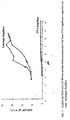
- Fig. 1 shows the separation efficiencies of basic proteins that can be achieved in CE separations for different capillaries produced in succession. If glutaraldehyde is used as a crosslinker, very high separation efficiencies (N> 400,000) for the strongly basic protein cytochrome C can be obtained in over 80% of the capillaries produced. However, if the coating is carried out without the crosslinking agent, separation efficiencies N greater than 400,000 are obtained only in 20% of the capillaries produced. In 30% percent of the capillaries produced in this way (No. 1, 5, 12, 15), no signal can be obtained for the strongly adsorptive protein; it was irreversibly adsorbed as on unoccupied capillaries.
- a PVA solution 450 ⁇ L solution of a 5% aqueous PVA solution with 50 ul of a 1: 1 with H 2 O diluted HCl mixed
- PVA MW about 90 000 99 +% hydrolyzed, Aldrich
- Both drops of liquid were then transported further through the column at 0.5 MPa. After 1-2 minutes they had left the column and the resulting layer was predried for 10 minutes in a stream of nitrogen.
- the capillary was then installed in a heatable oven (gas chromatograph) for accelerated drying and connected to the injector.
- a mixture of the following proteins was analyzed several times in a capillary of the effective length: 40.5 cm, the total length 54 cm and an inner diameter of 50 ⁇ m, produced by the process described above: cytochrome C, lysozyme trypsinogen and a -chymotripsinogen.
- the separation was carried out in an aqueous phosphate buffer with a concentration of 40 mmol L -1 at pH 3 and a voltage of 20 kV.
- Fig. 2 the first and the 91st separation obtained are plotted on top of each other. It can be seen that very good, reproducible separations are obtained with these capillaries.
- capillaries Two capillaries were covered with PVA analogously to Example 1, but without subsequent thermal treatment. There were 2 freshly coated capillaries dried for different lengths in a stream of nitrogen and the obtained Then capillaries for use in capillary electrophoresis analogous to Example 1 tested.
- the test mixture consisted of basic proteins: (1) Cytochrome C, (2) lysozyme, (3) trypsin, (4) trypsinogen and (5) a - Chymotripsinogen.
- the electropherograms obtained and the comparison with a separation that is obtained in an unused capillary Fig. 3 shown.
- PVA capillaries can also be operated with electrolytes that are very contain high proportions of organic solvents, this is especially for Coupling of the CE with a mass spectrometer (MS) necessary.
- MS mass spectrometer
- Analyte concentration 1 mg / ml, voltage: 15 kV, detection: UV 200 nm, electrolytes: A, B: 40 mML -1 Na phosphate, C: 45% methanol, 10% water, 45% acetonitrile, 20 mmol L -1 Ammonium acetate.
- the dependency was determined using a capillary produced analogously to Example 1 the electroosmotic flow from the pH of an aqueous electrolyte certainly.
- Na phosphate buffers were applied to the corresponding pH values titrated; the electroosmotic flow came from the migration period of the neutral marker DMSO.
- the ones obtained for a PVA capillary Results are in Fig. 5 with the corresponding results for compared an unused capillary.
- the EOF is suppressed over a wide pH range and, in contrast to unused capillaries, is almost independent of the pH.
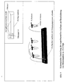
- the chip was included in a holder Seals placed and all 4 openings, each with an allocation device connected gastight via capillaries. This is shown schematically in Figure 6 shown. With the help of the occupancy equipment liquids can and gases through the microfluidic structures of the chip by means of pressure be moved.
- the channels in the chip were first completely filled with water.
- a glutaraldehyde solution 200 .mu.L of a 50% aqueous solution mixed with 300 .mu.l of a 1:10 dilute conc. HCl
- 0.5 MPa nitrogen was then passed through a fused silica capillary (inside diameter 50 .mu.m, length 30 cm) into the opening 1 of the microchip was pressed while the capillaries at openings 2, 3 and 4 were depressurized (see Figure 6).
- a PVA solution (450 ⁇ L strength of a 3% aqueous PVA solution with 50 ul of a 1: 1 mixed with H 2 O diluted HCl) (PVA: MW about 90 000 99 + hydrolysed%, Aldrich) with 0.5 MPa for 10 seconds by means of the capillary in opening 1 of the chip. Both drops of liquid were then transported further through the channels of the chip at 0.5 MPa. After 1-2 minutes they had left the chip's microfluidic channels via openings 2, 3 and 4. Then openings 2, 3 and 4 were pressurized with 0.5 MPa nitrogen pressure while relaxing at opening 1 in order to purge the channels with gas. The resulting layer on the surfaces of the channels was predried in a stream of nitrogen for 15 minutes.
- the chip was installed together with the holder and the capillaries in a heatable oven (gas chromatograph) for accelerated drying and the capillary was connected to the injector at opening 1. While purging the channels in a nitrogen stream (0.15-0.20 MPa), the furnace was heated from 40 ° C to 80 ° C at 6 ° C / min. heated up. After cooling and removing the chip, it was ready for use.
- CE chips with microchannels coated in this way were distinguished by a suppressed electroosmotic flow in both of the crossed channels.
- Example 5 After 1-2 minutes he had left the main channel of the chip through the capillary at opening 3. Then the openings 2, 3, 4 were pressurized with 0.5 MPa nitrogen pressure while relaxing at opening 1 in order to purge the channels with gas. The resulting layer on the surfaces were then dried as in Example 5.
Abstract
Description
Gegenstand der Erfindung ist ein Verfahren zur permanenten Beschichtung der inneren Oberfläche von Säulen, Kapillaren und Mikrokanalsystemen mit hydroxylischen Polymeren. Die Innenbeschichtung erfolgt durch Behandlung der zu belegenden Oberfläche mit der Lösung eines quervernetzenden Reagenz und der Lösung des Polymeren, was zu einer Immobilisierung des Polymers an der Kapillaroberfläche führt. Das beschriebene Verfahren ist besonders geeignet zur Beschichtung von fused-silica (FS) Kapillaren und Systemen mit mikrofluidischen Strukturen für die Kapillarelektrophorese mit einem stark hydrophilen Polymer wie Polyvinylalkohol. Weiterer Gegenstand der Erfindung sind die so hergestellten Säulen und Kapillaren, sowie deren Anwendung in der Kapillarelektrophorese und verwandten Techniken.The invention relates to a method for permanent coating the inner surface of columns, capillaries and microchannel systems hydroxylic polymers. The inner coating is done by treatment the surface to be covered with the solution of a cross-linking Reagent and the solution of the polymer, resulting in immobilization of the Polymer leads to the capillary surface. The procedure described is particularly suitable for coating fused silica (FS) capillaries and Systems with microfluidic structures for capillary electrophoresis with a highly hydrophilic polymer like polyvinyl alcohol. Another item the columns and capillaries thus produced, and their application in capillary electrophoresis and related techniques.
Mit Methoden der Kapillarelektrophorese (CE) können Trennungen von Gemischen unterschiedlicher Verbindungen durch differentielle Migration der Analyten in einem elektrischen Feld erhalten werden. Die Trennungen werden in der Regel in Kapillaren aus fused-silica, dies ist hochreines Quarzglas, die mit einem zumeist wäßrigen Elektrolyten gefüllt sind, durchgeführt. Die inneren Oberflächen deraitiger Kapillaren haben folgende Eigenschaften in ihrer Anwendung in der Kapillarelektrophorese:
- Aufgrund der aziden Silanolgruppen des FS-materials ist ein vom pH-Wert des Elektrolyten abhängiger elektroosmotischer Fluß (EOF) in Richtung zur Kathode wirksam. Der Betrag des EOF kann in unbelegten FS-Kapillaren jedoch stark schwanken und verschlechtert dadurch maßgeblich die Präzision und Reproduzierbarkeit von Analysen in der Kapillarelektrophorese.
- Die FS-Oberflächen verhalten sich sehr adsorptiv gegenüber vielen Verbindungen. Insbesondere basische Verbindungen und große Biopolymere, wie Proteine werden aus wäßrigen Lösungen stark adsorbiert. Dies verschlechtert die Qualität und Auflösung einer kapillarelektrophoretische Trennung solcher Verbindungen erheblich bzw. kann diese sogar unmöglich werden lassen.
- Due to the acidic silanol groups of the FS material, an electroosmotic flow (EOF) depending on the pH value of the electrolyte is effective towards the cathode. However, the amount of the EOF can fluctuate greatly in unused FS capillaries and thus significantly deteriorate the precision and reproducibility of analyzes in capillary electrophoresis.
- The FS surfaces behave very adsorptively towards many compounds. In particular, basic compounds and large biopolymers, such as proteins, are strongly adsorbed from aqueous solutions. This considerably deteriorates the quality and resolution of a capillary electrophoretic separation of such compounds or can even make them impossible.
Die Eigenschaften solcher Kapillaren können gezielt verändert werden, wenn die Kapillaroberfläche mit einer geeigneten Beschichtung versehen wird. Beschichtete FS-Kapillaren werden in der Kapillarelektrophorese aus folgenden Gründen eingesetzt:
- Zur Manipulation des elektroosmotischen Flusses: Durch Beschichtung der Oberfläche kann sowohl der Betrag, als auch die Richtung des EOF verändert werden. Dadurch kann eine CE-Trennung bezüglich Auflösung und Analysenzeit optimiert werden. Die Konstanz des EOF ist in beschichteten Kapillaren zumeist größer als in unbehandelten FS-Kapillaren mit der Folge verbesserter Reproduzierbarkeit und Wiederholbarkeit von CE-Analysen.
- Zur Unterdrückung der Wechselwirkungen zwischen Analyt und Wand werden Beschichtungen eingesetzt, die gegenüber den zu untersuchenden Verbindungen eine geringe Adsorptivität aufweisen. Dadurch werden höhere Trenneffizienzen adsorptiver Verbindungen, wie z.B. Proteine, und damit eine bessere Auflösung in kapillarelektrophoretischen Trennungen erreicht.
- For manipulating the electroosmotic flow: By coating the surface, both the amount and the direction of the EOF can be changed. This enables a CE separation to be optimized with regard to resolution and analysis time. The constancy of the EOF is usually greater in coated capillaries than in untreated FS capillaries, which results in improved reproducibility and repeatability of CE analyzes.
- To suppress the interactions between analyte and wall, coatings are used which have a low adsorptivity compared to the compounds to be investigated. This achieves higher separation efficiencies of adsorptive compounds, such as proteins, and thus better resolution in capillary electrophoretic separations.
Eine geeignete innere Beschichtung von Kapillaren für die CE sollte folgende Eigenschaften besitzen: i) einen konstanten EOF über einen weiten pH-Bereich, ii) Langzeitstabilität gegenüber unterschiedlichen Elektrolyten, iii) die Adsorptivität der Beschichtung gegenüber einer Vielfalt von Analyten sollte möglichst gering sein.A suitable inner coating of capillaries for the CE should follow Properties include: i) a constant EOF over a wide range pH range, ii) long-term stability against different electrolytes, iii) the adsorptivity of the coating to a variety of analytes should be as small as possible.
FS-Kapillaren lassen sich sehr leicht mit kationischen Polymeren wie Polybren® oder Polyvinylamin [M. Chiari, L. Ceriotti, G. Crini, und M. Morcellet; J. Chromatogr. A 836 (1999) 81] belegen, da diese stark an den entgegengesetzt geladenen FS-Oberflächen adsorbiert werden. Diese Kapillaren sind, wegen des umgekehrten, anodischen EOF, besonders zur beschleunigten Analyse sehr mobiler Anionen geeignet.FS capillaries can be easily removed with cationic polymers such as Polybren® or polyvinylamine [M. Chiari, L. Ceriotti, G. Crini, and M. Morcellet; J. Chromatogr. A 836 (1999) 81] because they are strongly adsorbed on the oppositely charged FS surfaces. Because of the reversed anodic EOF, these capillaries are particularly suitable for the accelerated analysis of very mobile anions.
Die Verwendung von hydrophilen nicht-ionischen Kapillarinnenbeschichtungen wie Polyacrylamid- oder Polyethylenglykol-Coatings hat sich in der Kapillarelektrophorese als besonders geeignet erwiesen, da diese Beschichtungen sowohl den EOF deutlich reduzieren, als auch die Adsorption von basischen Verbindungen und insbesondere von Proteinen an der Kapillarwand unterdrücken. Es wurden verschiedene Verfahren entwickelt, um hydrophile Moleküle, zumeist nach vorhergehender Silanisierung, chemisch an die FS-Kapillaroberfläche zu binden ( S. Hjerten; J. Chromatogr. 347 (1985) 191; G.M. Bruin, J.P. Chang; R.H. Kuhlmann, K. Zegers, J.C. Kraak und H. Poppe; J. Chromatogr. 471 (1989) 429; K.A. Cobb, V. Dolnik und M. Novotny; Anal. Chem. 62 (1990) 2478; A. Malik, Z. Zhao und M.L. Lee; J. Microcol. Sep. 5, (1993) 119).The use of hydrophilic non-ionic inner capillary coatings such as polyacrylamide or polyethylene glycol coatings has in the Capillary electrophoresis has been shown to be particularly suitable as these coatings significantly reduce both the EOF and the adsorption of basic compounds and especially of proteins on the capillary wall suppress. Various methods have been developed to hydrophilic molecules, mostly after previous silanization, chemically to bind to the FS capillary surface (S. Hjerten; J. Chromatogr. 347 (1985) 191; G.M. Bruin, J.P. Chang; R.H. Kuhlmann, K. Zegers, J.C. Kraak and H. Poppe; J. Chromatogr. 471 (1989) 429; K.A. Cobb, V. Dolnik and M. Novotny; Anal. Chem. 62 (1990) 2478; A. Malik, Z. Zhao and M.L. Lee; J. Microcol. Sep 5, (1993) 119).
Unter allen in der Literatur beschriebenen Kapillarbeschichtungen haben sich diejenigen auf Polyvinylalkohol (PVA) -Basis, welches als das hydrophilste Polymer anzusehen ist, als besonders leistungsfähig erwiesen. In Kapillaren, die mit PVA beschichtetet wurden, konnten insbesondere für Proteine außerordentlich hohe Trenneffizienzen erzielt werden. Zudem ist der Elektroosmotische Fluß über einen weiten pH-Bereich unterdrückt und sehr stabil (M. Gilges, H. Kleemiß und G. Schomburg; Anal. Chem. 66 (1994) 2038).Have under all capillary coatings described in the literature those based on polyvinyl alcohol (PVA), which is considered the most hydrophilic To be viewed as polymer is proven to be particularly powerful. In Capillaries that were coated with PVA could be used especially for Proteins extraordinarily high separation efficiencies can be achieved. In addition is the electroosmotic flow is suppressed over a wide pH range and very stable (M. Gilges, H. Kleemiß and G. Schomburg; Anal. Chem. 66 (1994) 2038).
Die Herstellung von mit Polyvinylalkohol beschichteten Kapillaren ist mit
herkömmlichen Verfahren relativ schwierig durchzuführen. Dies ist in den
besonderen Eigenschaften des Polyvinylalkohols begründet: i) Polyvinylalkohol
ist nur in Wasser löslich, daher sind klassische chemische Reaktionen
in organischen Lösungsmitteln zur Fixierung des Polymers an die Kapillaroberfläche,
wie z.B. durch Silanisierung, nicht möglich. ii) Wäßrige Lösungen
von Polyvinylalkohol benetzen wegen ihrer starken Hydrophilie die
fused-silica Kapillaren nur schlecht; daher ist es schwierig, allein durch Adsorption,
homogene Filme von Polyvinylalkohol auf den Kapillaroberflächen
zu erzeugen. Bisher sind folgende Verfahren beschrieben worden, um
PVA-beschichtete Kapillaren zu erzeugen:
Zielsetzung der Erfindung war ein schnelles und zuverlässiges Verfahren zur Belegung von Kapillaren mit hydroxylischen Polymeren, vorzugsweise mit Polyvinylalkohol, und deren Anwendung in elektromigrativen Trennverfahren.The aim of the invention was a fast and reliable method for covering capillaries with hydroxylic polymers, preferably with polyvinyl alcohol, and their use in electromigrative separation processes.
Diese Zielsetzung einer permanenten Polymerbeschichtung einer Kapillare, vorzugsweise mit Polyvinylalkohol, wird erreicht, indem das gelöste Polymer während des Belegungsvorganges chemisch vernetzt und an der Kapillarwand immobilisiert wird. Dazu wird ein gelöstes bi- oder multifunktionelles Reagenz, vorzugsweise ein Dialdehyd, wie z.B. Glutaraldehyd, in die Kapillare überführt. Danach wird ein Pfropfen der Polymerlösung, vorzugsweise eine Polyhydroxiverbindung, wie z.B. Polyvinylalkohol, z. B. mit Hilfe eines unter Überdruck stehenden Gases, wie Stickstoff oder andere laborübliche Gase, z. B. Helium, Argon, Wasserstoff, oder mit Hilfe eines Quecksilberpfropfes durch die Kapillare gedrückt. Die zwischen der Polymerlösung und dem Vernetzer eintretende Reaktion ermöglicht eine gute Benetzung der Kapillarwand mit der Polymerlösung und immobilisiert gleichzeitig die entstehende Polymerschicht auf der Kapillarwand. Die so erzeugten sehr stabilen Polymerbeschichtungen sind sofort nach Trocknung durch weiteres Spülen mit Gas einsatzfähig und zeigen folgende Eigenschaften in der Kapillarelektrophorese: unterdrückter EOF sowohl im sauren und als auch im alkalischen pH-Bereich, sehr hohe Trenneffizienzen für adsorptive Analyten wie basische Proteine, Langzeitstabilität bei Verwendung wäßriger und nicht wäßriger Elektrolyte, Beständigkeit gegenüber stark sauren und alkalischen Spüllösungen, wie verdünnte HCL- oder NaOH-Lösungen.This objective of permanent polymer coating of a capillary, preferably with polyvinyl alcohol, is achieved by the dissolved polymer chemically cross-linked during the coating process and on the capillary wall is immobilized. This is a solved bi- or multifunctional Reagent, preferably a dialdehyde, e.g. Glutaraldehyde, in the Capillary transferred. Thereafter, grafting the polymer solution is preferred a polyhydroxy compound, e.g. Polyvinyl alcohol, e.g. B. with the help of a gas under pressure, such as nitrogen or others laboratory gases, e.g. B. helium, argon, hydrogen, or with the help of a Mercury plug pushed through the capillary. The between the Polymer solution and the reaction occurring in the crosslinker enables one good wetting of the capillary wall with the polymer solution and immobilized at the same time the resulting polymer layer on the capillary wall. The so Very stable polymer coatings are produced immediately after drying usable by further flushing with gas and show the following properties in capillary electrophoresis: suppressed EOF both in acid and as well in the alkaline pH range, very high separation efficiencies for adsorptive analytes such as basic proteins, long-term stability when used aqueous and non-aqueous electrolytes, resistance to strongly acidic and alkaline rinsing solutions, such as dilute HCL or NaOH solutions.
Mit diesem Verfahren ist es möglich sehr schnell und mit großer Zuverlässigkeit PVA beschichtete Kapillaren hoher Qualität herzustellen. Der Beschichtungsvorgang dauert wenige Minuten, das Trocknen der Kapillaren erfolgt im Stickstoffstrom über mehrere Stunden. Die Trocknungszeit kann durch Erhöhung der Temperatur signifikant verkürzt werden, so daß die Kapillaren in weniger als einer Stunde verfügbar sein können.With this method it is possible very quickly and with great reliability Manufacture high quality PVA coated capillaries. The coating process takes a few minutes to dry the capillaries takes place in a stream of nitrogen for several hours. The drying time can can be significantly shortened by increasing the temperature, so that the Capillaries can be available in less than an hour.
Kapillaren, die entsprechend unserem Verfahren mit PVA und Glutaraldehyd
als Vernetzer belegt werden, sind im Vergleich zum analogen Verfahren
ohne Vernetzer (mit ausschließlich thermischer Immobilisierung), wesentlich
zuverlässiger herzustellen. In Abb. 1 sind die in CE-Trennungen
erreichbaren Trenneffizienzen basischer Proteine für verschiedene nacheinander
hergestellte Kapillaren dargestellt. Wird Glutaraldehyd als Vernetzer
eingesetzt, so können in über 80 % der hergestellten Kapillaren sehr hohe
Trenneffizienzen (N> 400.000) für das stark basische Protein Cytochrom C
erhalten werden.
Wird die Beschichtung jedoch ohne den Vernetzer durchgeführt, werden
nur in 20 % der hergestellten Kapillaren Trenneffizienzen N größer 400.000
erhalten. Bei 30% Prozent der so hergestellten Kapillaren (Nr. 1, 5, 12, 15)
kann für das stark adsorptive Protein kein Signal erhalten werden, es wurde
wie an unbelegten Kapillaren irreversibel adsorbiert.Capillaries, which are coated with PVA and glutaraldehyde as crosslinkers in accordance with our process, are much more reliable to produce than the analog process without crosslinker (with only thermal immobilization). Fig. 1 shows the separation efficiencies of basic proteins that can be achieved in CE separations for different capillaries produced in succession. If glutaraldehyde is used as a crosslinker, very high separation efficiencies (N> 400,000) for the strongly basic protein cytochrome C can be obtained in over 80% of the capillaries produced.
However, if the coating is carried out without the crosslinking agent, separation efficiencies N greater than 400,000 are obtained only in 20% of the capillaries produced. In 30% percent of the capillaries produced in this way (No. 1, 5, 12, 15), no signal can be obtained for the strongly adsorptive protein; it was irreversibly adsorbed as on unoccupied capillaries.
Mit unserem Verfahren lassen sich neben klassischen Kapillaren auch Oberflächen
von Systemen mit mikrofluidischen Strukturen, wie z.B. von Mikrokanälen
eines Kapillarelektrophorese Chips (CE-Chips) beschichten.
Damit wird es möglich den elektroosmotischen Fluß in CE-Chips zu unterdrücken,
sowie die Adsorption von Analyten wie z.B. Proteinen zu unterbinden.
Durch gezielte Beschichtung einzelner Mikrokanäle eines komplexeren
Systems, während andere unbeschichtet bleiben, lassen sich elektroosmotisch
induzierte Flüssigkeitsströmungen in Netzwerken von Mikrokanälen
gezielt manipulieren. So gelingt es für CE-Chips mit gekreuzten
Mikrokanälen, nur den für die Trennung relevanten Hauptkanal zu beschichten
und so die Analyse adsorptiver Proteine zu ermöglichen, während
der Injektionskanal unbeschichtet bleibt und eine elektroosmotische Injektion
in Richtung zur Kathode ermöglicht.
Unser Verfahren zur Herstellung polymerbeschichteter Kapillaren zeichnet
sich durch folgende Eigenschaften aus:
- Da das Verfahren auf chemischer Vernetzung des Polymers beruht,
eine chemische Bindung des Polymers an die Kapillarwand nicht erforderlich
ist, kann es auf unterschiedlichste Kapillarmaterialien angewandt
werden, wie z. B. Glas, fused silica", unterschiedliche Kunststoffe, wie Teflon, PEEK, Polyacrylate, und ist auch für unterschiedlich strukturierte Kanäle, wie z. B. klassische runde Kapillaren, (recht)-eckige Kanäle/Kapillaren und Mikrokanäle in mikrofluidischen Systemen (wie z.B. in CE-Chips) anwendbar.

- Das Verfahren ist einfach durchzuführen.
- Das Verfahren ist sehr schnell.
- Die erhaltenen Kapillaren lassen sich wiederholbar mit sehr hoher Qualität herstellen (geringer Ausschuß).
Our process for the production of polymer-coated capillaries is characterized by the following properties:
- Since the process is based on chemical crosslinking of the polymer, chemical bonding of the polymer to the capillary wall is not necessary, it can be applied to a wide variety of capillary materials, such as. B. glass, fused silica ", different plastics, such as Teflon, PEEK, polyacrylates, and is also suitable for differently structured channels, such as classic round capillaries, (right) corner channels / capillaries and microchannels in microfluidic systems (such as in CE Chips) applicable.
- The procedure is easy to do.
- The process is very quick.
- The capillaries obtained can be produced repeatedly with very high quality (low rejects).
Die nach diesem Verfahren hergestellten beschichteten Kapillaren haben folgende Eigenschaften:
- Sie sind wiederholt für Trennungen einsetzbar.
- Sie erlauben CE-Trennungen stark adsorptiver Verbindungen wie Proteine sowohl in sauren, als auch neutralen und alkalischen Elektrolyten.
- Der Elektroosmotische Fluß ist über einen weiten pH-Bereich,
mindestens von pH 2bis pH 10, stark reduziert und von hoher Konstanz. - Die chemisch immobilisierten PVA-Beschichtungen erweisen sich als stabil unter den Bedingungen der CE.
- Die Kapillaren sind insbesondere für folgende Anwendungen geeignet: CE-Trennungen basischer und azider Verbindungen, Kapillargelelektrophorese, isoelektrische Fokussierung, CE-Trennungen mit sehr geringen Ionenstärken des Elektrolyten und CE-Trennungen mit organischen Lösungsmitteln als Elektrolyte, wie zur Kopplung von Kapillarelektrophorese mit der Massenspektrometrie.
- Die erfindungsgemäß hergestellten Kapillaren und mikrofluidischen Systeme können u. a. zur Dosierung von zu analysierenden Proben z. B. in der Massenspektrometrie und für mikrosynthetische Verfahren in der Chemie eingesetzt werden.
- They can be used repeatedly for separations.
- They allow CE separations of strongly adsorptive compounds such as proteins in both acidic, neutral and alkaline electrolytes.
- The electroosmotic flow is greatly reduced over a wide pH range, at least from
pH 2 topH 10, and is of high constancy. - The chemically immobilized PVA coatings have proven to be stable under the conditions of the CE.
- The capillaries are particularly suitable for the following applications: CE separations of basic and acidic compounds, capillary gel electrophoresis, isoelectric focusing, CE separations with very low ionic strengths of the electrolyte and CE separations with organic solvents as electrolytes, such as for coupling capillary electrophoresis with mass spectrometry.
- The capillaries and microfluidic systems produced according to the invention can be used, for example, for metering samples to be analyzed. B. in mass spectrometry and for microsynthetic processes in chemistry.
Um eine für die Kapillarelektrophorese geeignete Trennsäule herzustellen,
wurde für die nachfolgende Beschichtung eine handelsübliche
In einer nach dem oben beschriebenen Verfahren hergestellten Kapillare der
effektiven Länge: 40,5 cm der Gesamtlänge 54 cm und einem Innendurchmesser
von 50 µm wurde eine Mischung folgender Proteine mehrfach analysiert:
Cytochrom C, Lysozym Trypsinogen und a -Chymotripsinogen. Die
Trennung erfolgte in einem wäßrigen Phosphatpuffer der Konzentration 40
mMol L-1 bei pH 3 und einer Spannung von 20 kV. In Abb. 2 sind die erste
und die 91-te erhaltene Trennung übereinander geplottet. Es ist zu erkennen,
daß mit diesen Kapillaren sehr gute, reproduzierbare Trennungen erhalten
werden.A mixture of the following proteins was analyzed several times in a capillary of the effective length: 40.5 cm, the total length 54 cm and an inner diameter of 50 μm, produced by the process described above: cytochrome C, lysozyme trypsinogen and a -chymotripsinogen. The separation was carried out in an aqueous phosphate buffer with a concentration of 40 mmol L -1 at
Zwei Kapillaren wurden analog zu Beispiel 1 mit PVA belegt, jedoch ohne nachfolgende thermische Behandlung. Es wurden 2 frisch gecoatete Kapillaren unterschiedlich lang im Stickstoffstrom getrocknet und die erhaltenen Kapillaren dann für den Einsatz in der Kapillarelektrophorese analog zu Beispiel 1 getestet. Die Testmischung bestand aus basischen Proteinen: (1) Cytochrom C, (2) Lysozym, (3) Trypsin, (4) Trypsinogen und (5) a - Chymotripsinogen. Die erhaltenen Elektropherogramme und der Vergleich mit einer Trennung, die in einer unbelegten Kapillare erhalten wird ist in Abb. 3 dargestellt. In einer unbelegten Kapillare können wegen der starken Adsorption der Proteine keine effizienten Trennungen erhalten werden, das stark adsorptive Protein Cytochrom C wird sogar vollständig adsobiert und eluiert nicht aus der Säule, siehe Abb. 3A. Mit einer nach unserem Verfahren hergestellten PVA-Kapillare werden hocheffiziente Signale aller Testverbindungen erhalten. Wird die Trocknung der PVA-Beschichtung im Gasstrom durchgeführt, so werden nach dem Trocknen der Beschichtung über 5 Stunden stabile und sehr effiziente Säulen erhalten. Wird nur für 10 Minuten im Gasstrom getrocknet, so sind die Trenneffizienzen N (in theoretischen Bodenzahlen) für stark adsorptive Verbindungen wie Cytochrom C geringer.Two capillaries were covered with PVA analogously to Example 1, but without subsequent thermal treatment. There were 2 freshly coated capillaries dried for different lengths in a stream of nitrogen and the obtained Then capillaries for use in capillary electrophoresis analogous to Example 1 tested. The test mixture consisted of basic proteins: (1) Cytochrome C, (2) lysozyme, (3) trypsin, (4) trypsinogen and (5) a - Chymotripsinogen. The electropherograms obtained and the comparison with a separation that is obtained in an unused capillary Fig. 3 shown. In an unused capillary can because of the strong Adsorption of the proteins does not result in efficient separations highly adsorptive protein cytochrome C is even completely adsorbed and does not elute from the column, see Fig. 3A. With one according to our procedure manufactured PVA capillaries are highly efficient signals of all test connections receive. Is the drying of the PVA coating in the Gas flow is carried out after the coating has dried Get stable and very efficient columns for over 5 hours. Will only be for 10 Dried minutes in a gas stream, the separation efficiencies are N (in theoretical Soil numbers) for strongly adsorptive compounds such as cytochrome C lower.
Mit einer Analog zu Beispiel 1 hergestellten Kapillare wurden basische Dendrimere analysiert. Diese Verbindungen sind sehr adsorptiv gegenüber fused-silica. Mit einer unbelegten Kapillare kann wegen der Peakverbreiterung der adsorbierten Analyten daher nur eine schlechte CE-Trennung erhalten werden, siehe Abb. 4A. Wird die Trennung mit gleichen experimentellen Parametern aber mit einer PVA beschichteten Kapillare durchgeführt wird die Adsorption der Verbindungen an der Kapillarwand wirksam unterdrückt und es werden sehr scharfe Signale erhalten. Dies ist in Abb. 4B gezeigt.With a capillary prepared analogously to Example 1, basic Analyzed dendrimers. These compounds are very adsorptive towards fused silica. With an unoccupied capillary can because of the peak broadening of the analytes adsorbed therefore received only poor CE separation see Fig.4A. If the separation is the same experimental Parameters but carried out with a PVA coated capillary the adsorption of the compounds on the capillary wall is effectively suppressed and very sharp signals are obtained. This is shown in Fig. 4B.
PVA-Kapillaren können auch mit Elektrolyten betrieben werden, die sehr hohe Anteile organischer Lösungsmittel enthalten, dies ist insbesondere zur Kopplung der CE mit einem Massenspektrometer (MS) notwendig. Die CE Trennung von Dendrimeren in einem zum MS kompatiblen Elektrolyten ist in Abb. 4C dargestellt.PVA capillaries can also be operated with electrolytes that are very contain high proportions of organic solvents, this is especially for Coupling of the CE with a mass spectrometer (MS) necessary. The CE Separation of dendrimers in an electrolyte compatible with MS shown in Fig. 4C.
Analytkonzentration: 1mg/ml, Spannung: 15 kV, Detektion: UV 200 nm, Elektrolyte: A,B: 40 mML-1 Na- Phosphat, C: 45% Methanol, 10 % Wasser, 45% Acetonitril, 20 mMol L-1 Ammoniumacetat. Analyte concentration: 1 mg / ml, voltage: 15 kV, detection: UV 200 nm, electrolytes: A, B: 40 mML -1 Na phosphate, C: 45% methanol, 10% water, 45% acetonitrile, 20 mmol L -1 Ammonium acetate.
Mit einer analog zu Beispiel 1 hergestellten Kapillare wurde die Abhängigkeit des elektroosmotischen Flusses vom pH-Wert eines wäßrigen Elektrolyten bestimmt. Dazu wurden Na-Phosphatpuffer auf die entsprechenden pH-Werte titriert; der elektroosmotische Fluß wurde aus der Migrationszeit des neutralen Markers DMSO bestimmt. Die für eine PVA-Kapillare erhaltenen Ergebnisse sind in Abb. 5 mit den entsprechenden Ergebnissen für eine unbelegte Kapillare verglichen. In einer nach unserem Verfahren mit PVA belegten Kapillare ist der EOF über einen weiten pH-Bereich unterdrückt und ist, im Gegensatz zu unbelegten Kapillaren, nahezu unabhängig vom pH-Wert.The dependency was determined using a capillary produced analogously to Example 1 the electroosmotic flow from the pH of an aqueous electrolyte certainly. For this purpose, Na phosphate buffers were applied to the corresponding pH values titrated; the electroosmotic flow came from the migration period of the neutral marker DMSO. The ones obtained for a PVA capillary Results are in Fig. 5 with the corresponding results for compared an unused capillary. In one using our procedure In the PVA-coated capillary, the EOF is suppressed over a wide pH range and, in contrast to unused capillaries, is almost independent of the pH.
Ein CE-Chip aus Borofloatglas mit mikrofluidischen Kanälen (20 µm Tiefe,
50 µm Breite, Länge des Injektionskanals 8 mm, Länge des Hauptkanals 85
mm) der Firma Micralyne (Edmonton, Kanada), wurde gemäß unseres Verfahrens
mit PVA belegt. Dazu wurde der Chip in einer Halterung mit
Dichtungen plaziert und alle 4 Öffnungen mit jeweils einer Belegungsapparatur
über Kapillaren gasdicht verbunden. Dies ist schematisch in Abbildung
6 gezeigt. Mit Hilfe der Belegungsapparaturen können Flüssigkeiten
und Gase durch die mikrofluidischen Strukturen des Chips mittels Druck
bewegt werden. A borofloat glass CE chip with microfluidic channels (20 µm deep,
50 µm width, length of the
Zur Belegung aller Kanäle im Chip wurden zunächst die Kanäle im Chip
vollständig, mit Wasser gefüllt. Danach wurde eine Glutaraldehydlösung
(200 µL einer 50%igen wäßrigen Lösung mit 300 µl einer 1:10 verdünnten
konz. HCl gemischt) mit 0,5 MPa Stickstoff über eine fused silica Kapillare
(Innendurchmesser 50 µm, Länge 30 cm), in die Öffnung 1 des Mikrochips
gedrückt, während die Kapillaren an Öffnung 2, 3 und 4 drucklos waren
(siehe Abbildung 6). Unmittelbar danach wurde eine PVA-Lösung (450µL
einer 3%igen wäßrigen PVA-Lösung mit 50 µl einer 1:1 mit H2O verdünnten
HCl gemischt), (PVA: MW ca. 90 000, 99+% hydrolysiert,
Aldrich) mit 0,5 MPa für 10 Sekunden mittels der Kapillare in Öffnung 1
des Chips gedrückt. Beide Flüssigkeitspfropfen wurden anschließend mit
0,5 MPa weiter durch die Kanäle des Chips transportiert. Nach 1-2 Minuten
hatten sie die mikrofluiden Kanäle des Chips über die Öffnungen 2, 3 und 4
verlassen. Danach wurden die Öffnungen 2, 3 und 4 mit 0,5 MPa Stickstoffdruck
beaufschlagt während an Öffnung 1 entspannt wurde um die Kanäle
mit Gas zu spülen. Die entstandene Schicht an den Oberflächen der
Kanäle wurde so für 15 Minuten im Stickstoffstrom vorgetrocknet. Danach
wurde zur beschleunigten Trocknung der Chip zusammen mit der Halterung
und den Kapillaren in einen heizbaren Ofen (Gaschromatographen) eingebaut
und die Kapillare an Öffnung 1 mit dem Injektor verbunden. Während
man die Kanäle im Stickstoffstrom (0,15 - 0,20 MPa) spülte, wurde der
Ofen von 40°C bis 80°C mit 6°C/min. aufgeheizt. Nach Abkühlen und Ausbau
des Chips war er für den Gebrauch fertig. CE-Chips mit so beschichteten
Mikrokanälen zeichneten sich durch einen unterdrückten elektroosmotisehen
Fluß in beiden der gekreuzten Kanäle aus.To occupy all channels in the chip, the channels in the chip were first completely filled with water. A glutaraldehyde solution (200 .mu.L of a 50% aqueous solution mixed with 300 .mu.l of a 1:10 dilute conc. HCl) with 0.5 MPa nitrogen was then passed through a fused silica capillary (inside diameter 50 .mu.m,
Nach unserem Verfahren in Kombination mit dem in Beispiel 5 beschriebenen
experimentellen Aufbau lassen sich auch einzelne ausgewählte Kanäle
von Systemen mit mikrofluidischen Strukturen beschichten. So gelingt es
bei einem CE-chip mit zwei gekreuzten Kanälen nur einen mit PVA zu belegen,
während der andere unbeschichtet bleibt und daher nur dort ein starker
EOF präsent ist.
Zur alleinigen Belegung des Hauptkanals (Kanal zwischen Öffnung 1 und
3, siehe Abb. 6) in dem die elektrophoretische Trennung stattfindet, während
der kürzere Kanal für die Probenaufgabe unbelegt bleibt (Kanal zwischen
Öffnung 2 und 4, siehe Abb. 6), wurde der Chip analog zu Beispiel 5
mit 4 Belegungsapparaturen verbunden und die Kanäle wurden vollständig
mit Wasser gefüllt. Danach wurde eine Glutaraldehydlösung (200 µL einer
50%igen wäßrigen Lösung mit 300 µl einer 1:10 verdünnten konz. HCl gemischt)
mit 0,5 MPa Stickstoff über eine fused silica Kapillare (Innendurchmesser
50 µm, Länge 30 cm), in die Öffnung 1 des Mikrochips gedrückt,
während über die Kapillaren an Öffnung 2 und 4 Wasser mit einem
Druck von 0,1 MPa zugeführt wurde, (siehe Abbildung 6). Nachdem die
Glutaraldehydlösung an der Kapillare an Öffnung 3 austrat, wurde eine
PVA-Lösung analog zu Beispiel 5, mit 0,5 MPa für 10 Sekunden über die
Kapillare in Öffnung 1 des Chips gedrückt, während über Öffnung 2 und 4
wiederum mit Wasser gespült wurde. Der PVA-Flüssigkeitspfropfen wurde
anschließend mit 0,5 MPa im Stickstoffstrom weiter durch den Hauptkanal
des Chips transportiert. Nach 1-2 Minuten hatte er den Hauptkanal des
Chips über die Kapillare an Öffnung 3 verlassen. Danach wurden die Öffnungen
2, 3, 4 mit 0,5 MPa Stickstoffdruck beaufschlagt während an Öffnung
1 entspannt wurde um die Kanäle mit Gas zu spülen. Die entstandene
Schicht an den Oberflächen wurden danach wie in Beispiel 5 getrocknet. Our method in combination with the experimental setup described in Example 5 can also be used to coat individual selected channels of systems with microfluidic structures. With a CE chip with two crossed channels, only one can be covered with PVA, while the other remains uncoated and therefore only has a strong EOF.
For the sole occupancy of the main channel (channel between
CE-Chips mit einem so beschichteten Hauptkanal zeichneten sich dort durch einen unterdrückten elektroosmotischen Fluß aus, während ein starker kathodischer Fluß im Probenaufgabekanal vorhanden war.CE chips with a main channel coated in this way stood out there by a suppressed electroosmotic flow, while a strong one cathodic flow was present in the sample feed channel.
Claims (17)
Applications Claiming Priority (2)
| Application Number | Priority Date | Filing Date | Title |
|---|---|---|---|
| DE19938002 | 1999-08-11 | ||
| DE19938002A DE19938002A1 (en) | 1999-08-11 | 1999-08-11 | Coating with cross-linked hydrophilic polymers |
Publications (3)
| Publication Number | Publication Date |
|---|---|
| EP1076239A2 true EP1076239A2 (en) | 2001-02-14 |
| EP1076239A3 EP1076239A3 (en) | 2001-05-30 |
| EP1076239B1 EP1076239B1 (en) | 2003-09-24 |
Family
ID=7918021
Family Applications (1)
| Application Number | Title | Priority Date | Filing Date |
|---|---|---|---|
| EP00116757A Expired - Lifetime EP1076239B1 (en) | 1999-08-11 | 2000-08-03 | Process for the coating of capillaries with cross-linked hydrophilic polymers |
Country Status (6)
| Country | Link |
|---|---|
| US (1) | US6596238B1 (en) |
| EP (1) | EP1076239B1 (en) |
| JP (1) | JP2001124737A (en) |
| AT (1) | ATE250762T1 (en) |
| CA (1) | CA2315479A1 (en) |
| DE (2) | DE19938002A1 (en) |
Cited By (3)
| Publication number | Priority date | Publication date | Assignee | Title |
|---|---|---|---|---|
| WO2001047637A1 (en) * | 1999-12-23 | 2001-07-05 | Gyros Ab | Microfluidic surfaces |
| EP1548429A1 (en) * | 2002-09-05 | 2005-06-29 | Katayanagi Institute | Method for separating substances |
| WO2005075079A1 (en) * | 2004-02-04 | 2005-08-18 | Studiengesellschaft Kohle Mbh | Microfluidic chips having immanent hydrophilic surfaces |
Families Citing this family (26)
| Publication number | Priority date | Publication date | Assignee | Title |
|---|---|---|---|---|
| US6911132B2 (en) | 2002-09-24 | 2005-06-28 | Duke University | Apparatus for manipulating droplets by electrowetting-based techniques |
| US7329545B2 (en) | 2002-09-24 | 2008-02-12 | Duke University | Methods for sampling a liquid flow |
| JP4521754B2 (en) * | 2004-03-31 | 2010-08-11 | 富山県 | Capillary tube and manufacturing method thereof |
| ES2390800T3 (en) | 2005-01-28 | 2012-11-16 | Duke University | Apparatus and methods for handling droplets on a printed circuit board |
| CN101237934B (en) * | 2005-05-21 | 2012-12-19 | 先进液体逻辑公司 | Mitigation of biomolecular adsorption with hydrophilic polymer additives |
| US9410889B2 (en) | 2005-06-10 | 2016-08-09 | Applied Biosystem, Llc | Method and system for multiplex genetic analysis |
| US8613889B2 (en) * | 2006-04-13 | 2013-12-24 | Advanced Liquid Logic, Inc. | Droplet-based washing |
| US8637317B2 (en) * | 2006-04-18 | 2014-01-28 | Advanced Liquid Logic, Inc. | Method of washing beads |
| US9476856B2 (en) | 2006-04-13 | 2016-10-25 | Advanced Liquid Logic, Inc. | Droplet-based affinity assays |
| US20140193807A1 (en) | 2006-04-18 | 2014-07-10 | Advanced Liquid Logic, Inc. | Bead manipulation techniques |
| US8492168B2 (en) * | 2006-04-18 | 2013-07-23 | Advanced Liquid Logic Inc. | Droplet-based affinity assays |
| US8809068B2 (en) | 2006-04-18 | 2014-08-19 | Advanced Liquid Logic, Inc. | Manipulation of beads in droplets and methods for manipulating droplets |
| US7727723B2 (en) | 2006-04-18 | 2010-06-01 | Advanced Liquid Logic, Inc. | Droplet-based pyrosequencing |
| WO2007123908A2 (en) | 2006-04-18 | 2007-11-01 | Advanced Liquid Logic, Inc. | Droplet-based multiwell operations |
| US8637324B2 (en) | 2006-04-18 | 2014-01-28 | Advanced Liquid Logic, Inc. | Bead incubation and washing on a droplet actuator |
| US8980198B2 (en) | 2006-04-18 | 2015-03-17 | Advanced Liquid Logic, Inc. | Filler fluids for droplet operations |
| US7901947B2 (en) | 2006-04-18 | 2011-03-08 | Advanced Liquid Logic, Inc. | Droplet-based particle sorting |
| US8658111B2 (en) | 2006-04-18 | 2014-02-25 | Advanced Liquid Logic, Inc. | Droplet actuators, modified fluids and methods |
| US8716015B2 (en) | 2006-04-18 | 2014-05-06 | Advanced Liquid Logic, Inc. | Manipulation of cells on a droplet actuator |
| US10078078B2 (en) | 2006-04-18 | 2018-09-18 | Advanced Liquid Logic, Inc. | Bead incubation and washing on a droplet actuator |
| US7439014B2 (en) | 2006-04-18 | 2008-10-21 | Advanced Liquid Logic, Inc. | Droplet-based surface modification and washing |
| KR101553679B1 (en) * | 2007-01-12 | 2015-09-17 | 보오드 오브 리젠츠, 더 유니버시티 오브 텍사스 시스템 | - interfacing low-flow separation techniques |
| BRPI0806831B8 (en) | 2007-02-09 | 2021-07-27 | Advanced Liquid Logic Inc | droplet actuating methods employing magnetic spheres |
| US8268246B2 (en) | 2007-08-09 | 2012-09-18 | Advanced Liquid Logic Inc | PCB droplet actuator fabrication |
| AU2009272430A1 (en) | 2008-07-15 | 2010-01-21 | L3 Technology Limited | Assay device and methods |
| US9513253B2 (en) | 2011-07-11 | 2016-12-06 | Advanced Liquid Logic, Inc. | Droplet actuators and techniques for droplet-based enzymatic assays |
Citations (5)
| Publication number | Priority date | Publication date | Assignee | Title |
|---|---|---|---|---|
| US4796700A (en) * | 1984-06-25 | 1989-01-10 | Cities Service Oil And Gas Corporation | Process for retarding fluid flow |
| EP0587156A1 (en) * | 1992-09-11 | 1994-03-16 | Studiengesellschaft Kohle mbH | Deactivation of the inner surfaces of capillaries |
| US5322608A (en) * | 1992-12-23 | 1994-06-21 | Northeastern University | Siloxandediol coating for capillary electrophoresis and for general surface modification |
| WO1996023221A1 (en) * | 1995-01-27 | 1996-08-01 | Beckman Instruments, Inc. | Polyvinylalcohol coated capillary electrophoresis columns |
| WO1999020378A1 (en) * | 1997-10-20 | 1999-04-29 | Korea Research Institute Of Chemical Technology | A manufacturing method of composite membrane having hydrophilic coating layer on hydrophobic support membrane |
Family Cites Families (5)
| Publication number | Priority date | Publication date | Assignee | Title |
|---|---|---|---|---|
| US4680201A (en) * | 1985-10-30 | 1987-07-14 | Stellan Hjerten | Coating for electrophoresis tube |
| US4865707A (en) * | 1986-10-21 | 1989-09-12 | Northeastern University | Capillary gel electrophoresis columns |
| US5221447A (en) * | 1991-12-06 | 1993-06-22 | Bio-Rad Laboratories, Inc. | Hydrophilic polymer coating of high pH stability for silica surfaces for suppression of electroendomosis and solute adsorption |
| DE69633962T2 (en) * | 1995-01-27 | 2005-12-01 | Northeastern University, Boston | A method of forming a covalently bonded hydrophilic layer based on polyvinyl alcohol for capillary electrophoresis |
| US5792331A (en) * | 1996-12-19 | 1998-08-11 | Dionex Corporation | Preformed polymer coating process and product |
-
1999
- 1999-08-11 DE DE19938002A patent/DE19938002A1/en not_active Withdrawn
-
2000
- 2000-08-03 DE DE50003808T patent/DE50003808D1/en not_active Expired - Lifetime
- 2000-08-03 EP EP00116757A patent/EP1076239B1/en not_active Expired - Lifetime
- 2000-08-03 AT AT00116757T patent/ATE250762T1/en not_active IP Right Cessation
- 2000-08-09 US US09/634,770 patent/US6596238B1/en not_active Expired - Lifetime
- 2000-08-10 CA CA002315479A patent/CA2315479A1/en not_active Abandoned
- 2000-08-11 JP JP2000244379A patent/JP2001124737A/en active Pending
Patent Citations (5)
| Publication number | Priority date | Publication date | Assignee | Title |
|---|---|---|---|---|
| US4796700A (en) * | 1984-06-25 | 1989-01-10 | Cities Service Oil And Gas Corporation | Process for retarding fluid flow |
| EP0587156A1 (en) * | 1992-09-11 | 1994-03-16 | Studiengesellschaft Kohle mbH | Deactivation of the inner surfaces of capillaries |
| US5322608A (en) * | 1992-12-23 | 1994-06-21 | Northeastern University | Siloxandediol coating for capillary electrophoresis and for general surface modification |
| WO1996023221A1 (en) * | 1995-01-27 | 1996-08-01 | Beckman Instruments, Inc. | Polyvinylalcohol coated capillary electrophoresis columns |
| WO1999020378A1 (en) * | 1997-10-20 | 1999-04-29 | Korea Research Institute Of Chemical Technology | A manufacturing method of composite membrane having hydrophilic coating layer on hydrophobic support membrane |
Cited By (5)
| Publication number | Priority date | Publication date | Assignee | Title |
|---|---|---|---|---|
| WO2001047637A1 (en) * | 1999-12-23 | 2001-07-05 | Gyros Ab | Microfluidic surfaces |
| US7955575B2 (en) | 1999-12-23 | 2011-06-07 | Gyros Patent Ab | Microfluidic surfaces |
| EP1548429A1 (en) * | 2002-09-05 | 2005-06-29 | Katayanagi Institute | Method for separating substances |
| EP1548429A4 (en) * | 2002-09-05 | 2009-06-17 | Katayanagi Inst | Method for separating substances |
| WO2005075079A1 (en) * | 2004-02-04 | 2005-08-18 | Studiengesellschaft Kohle Mbh | Microfluidic chips having immanent hydrophilic surfaces |
Also Published As
| Publication number | Publication date |
|---|---|
| CA2315479A1 (en) | 2001-02-11 |
| ATE250762T1 (en) | 2003-10-15 |
| DE50003808D1 (en) | 2003-10-30 |
| EP1076239A3 (en) | 2001-05-30 |
| US6596238B1 (en) | 2003-07-22 |
| EP1076239B1 (en) | 2003-09-24 |
| JP2001124737A (en) | 2001-05-11 |
| DE19938002A1 (en) | 2001-02-15 |
Similar Documents
| Publication | Publication Date | Title |
|---|---|---|
| EP1076239B1 (en) | Process for the coating of capillaries with cross-linked hydrophilic polymers | |
| EP2235514B1 (en) | Gas sensor with microporous electrolyte layer | |
| DE69633962T2 (en) | A method of forming a covalently bonded hydrophilic layer based on polyvinyl alcohol for capillary electrophoresis | |
| Gbatu et al. | Electrochemical control of solid phase micro-extraction using unique conducting polymer coated fibers | |
| DE19645070A1 (en) | Integrated planar liquid handling system for matrix-assisted laser desorption / ionization time-of-flight mass spectroscopy | |
| EP0787290A1 (en) | Analyte-selective sensor | |
| DE19959264A1 (en) | Template-embossed composite materials with high binding specificity and selectivity, processes for their production and their use | |
| EP3729067B1 (en) | Reference electrode for potentiometric measurement of ion concentrations | |
| DE4135516A1 (en) | SUPPRESSION OF ELECTROOSMOSIS WITH HYDROLYTICALLY STABLE COATINGS | |
| EP2252410B1 (en) | Surface modification | |
| EP2453229B1 (en) | Oxygen sensor with a microporous electrolyte layer and partially open cover membrane | |
| Harnisch et al. | Electrochemically modulated liquid chromatography: an electrochemical strategy for manipulating chromatographic retention | |
| DE10322701B4 (en) | Sample carriers using a porous film comprising metal oxide particles, methods for producing a sample carrier, use of the sample carrier and methods for the selective detection of phosphorylated / sulfated biopolymers, in particular peptides / proteins | |
| EP0546032B1 (en) | Immobilization of organic macromolecules or biopolymers in a polymer membrane | |
| EP1807699B1 (en) | Structured copolymer supports for use in spectrometry or spectroscopy | |
| DE4230403A1 (en) | Deactivation of the inner surface of capillaries | |
| DE4135545C2 (en) | Capillary gels that are formed by spatially progressing polymerization using a migrating initiator | |
| EP3752552B1 (en) | Container for storing a bodily fluid | |
| WO2005075079A1 (en) | Microfluidic chips having immanent hydrophilic surfaces | |
| AT397661B (en) | Outer membrane layer of an enzyme electrode | |
| DE10053006B4 (en) | Electrically conductive polymer material, its preparation and use | |
| US9481778B2 (en) | Initiator-tightened compositions | |
| JP5378623B2 (en) | Packing material for ion exchange liquid chromatography and analysis method of glycated hemoglobin | |
| EP1754053A1 (en) | Open tubular capillaries comprising a connection layer | |
| DE19907296A1 (en) | Use of carrier material in capillary electrochromatography |
Legal Events
| Date | Code | Title | Description |
|---|---|---|---|
| PUAI | Public reference made under article 153(3) epc to a published international application that has entered the european phase |
Free format text: ORIGINAL CODE: 0009012 |
|
| AK | Designated contracting states |
Kind code of ref document: A2 Designated state(s): AT BE CH CY DE DK ES FI FR GB GR IE IT LI LU MC NL PT SE |
|
| AX | Request for extension of the european patent |
Free format text: AL;LT;LV;MK;RO;SI |
|
| PUAL | Search report despatched |
Free format text: ORIGINAL CODE: 0009013 |
|
| 17P | Request for examination filed |
Effective date: 20010303 |
|
| AK | Designated contracting states |
Kind code of ref document: A3 Designated state(s): AT BE CH CY DE DK ES FI FR GB GR IE IT LI LU MC NL PT SE |
|
| AX | Request for extension of the european patent |
Free format text: AL;LT;LV;MK;RO;SI |
|
| 17Q | First examination report despatched |
Effective date: 20011121 |
|
| AKX | Designation fees paid |
Free format text: AT BE CH CY DE DK ES FI FR GB GR IE IT LI LU MC NL PT SE |
|
| GRAH | Despatch of communication of intention to grant a patent |
Free format text: ORIGINAL CODE: EPIDOS IGRA |
|
| RTI1 | Title (correction) |
Free format text: PROCESS FOR THE COATING OF CAPILLARIES WITH CROSS-LINKED HYDROPHILIC POLYMERS |
|
| GRAS | Grant fee paid |
Free format text: ORIGINAL CODE: EPIDOSNIGR3 |
|
| GRAA | (expected) grant |
Free format text: ORIGINAL CODE: 0009210 |
|
| AK | Designated contracting states |
Kind code of ref document: B1 Designated state(s): AT BE CH CY DE DK ES FI FR GB GR IE IT LI LU MC NL PT SE |
|
| PG25 | Lapsed in a contracting state [announced via postgrant information from national office to epo] |
Ref country code: IT Free format text: LAPSE BECAUSE OF FAILURE TO SUBMIT A TRANSLATION OF THE DESCRIPTION OR TO PAY THE FEE WITHIN THE PRESCRIBED TIME-LIMIT;WARNING: LAPSES OF ITALIAN PATENTS WITH EFFECTIVE DATE BEFORE 2007 MAY HAVE OCCURRED AT ANY TIME BEFORE 2007. THE CORRECT EFFECTIVE DATE MAY BE DIFFERENT FROM THE ONE RECORDED. Effective date: 20030924 Ref country code: FI Free format text: LAPSE BECAUSE OF FAILURE TO SUBMIT A TRANSLATION OF THE DESCRIPTION OR TO PAY THE FEE WITHIN THE PRESCRIBED TIME-LIMIT Effective date: 20030924 Ref country code: IE Free format text: LAPSE BECAUSE OF FAILURE TO SUBMIT A TRANSLATION OF THE DESCRIPTION OR TO PAY THE FEE WITHIN THE PRESCRIBED TIME-LIMIT Effective date: 20030924 Ref country code: CY Free format text: LAPSE BECAUSE OF FAILURE TO SUBMIT A TRANSLATION OF THE DESCRIPTION OR TO PAY THE FEE WITHIN THE PRESCRIBED TIME-LIMIT Effective date: 20030924 |
|
| REG | Reference to a national code |
Ref country code: GB Ref legal event code: FG4D Free format text: NOT ENGLISH |
|
| REG | Reference to a national code |
Ref country code: CH Ref legal event code: NV Representative=s name: A. BRAUN, BRAUN, HERITIER, ESCHMANN AG PATENTANWAE Ref country code: CH Ref legal event code: EP |
|
| REG | Reference to a national code |
Ref country code: SE Ref legal event code: TRGR |
|
| REG | Reference to a national code |
Ref country code: IE Ref legal event code: FG4D Free format text: GERMAN |
|
| REF | Corresponds to: |
Ref document number: 50003808 Country of ref document: DE Date of ref document: 20031030 Kind code of ref document: P |
|
| PG25 | Lapsed in a contracting state [announced via postgrant information from national office to epo] |
Ref country code: GR Free format text: LAPSE BECAUSE OF FAILURE TO SUBMIT A TRANSLATION OF THE DESCRIPTION OR TO PAY THE FEE WITHIN THE PRESCRIBED TIME-LIMIT Effective date: 20031224 Ref country code: DK Free format text: LAPSE BECAUSE OF FAILURE TO SUBMIT A TRANSLATION OF THE DESCRIPTION OR TO PAY THE FEE WITHIN THE PRESCRIBED TIME-LIMIT Effective date: 20031224 |
|
| GBT | Gb: translation of ep patent filed (gb section 77(6)(a)/1977) |
Effective date: 20031209 |
|
| PG25 | Lapsed in a contracting state [announced via postgrant information from national office to epo] |
Ref country code: ES Free format text: LAPSE BECAUSE OF FAILURE TO SUBMIT A TRANSLATION OF THE DESCRIPTION OR TO PAY THE FEE WITHIN THE PRESCRIBED TIME-LIMIT Effective date: 20040104 |
|
| REG | Reference to a national code |
Ref country code: IE Ref legal event code: FD4D |
|
| ET | Fr: translation filed | ||
| PLBE | No opposition filed within time limit |
Free format text: ORIGINAL CODE: 0009261 |
|
| STAA | Information on the status of an ep patent application or granted ep patent |
Free format text: STATUS: NO OPPOSITION FILED WITHIN TIME LIMIT |
|
| PG25 | Lapsed in a contracting state [announced via postgrant information from national office to epo] |
Ref country code: LU Free format text: LAPSE BECAUSE OF NON-PAYMENT OF DUE FEES Effective date: 20040803 |
|
| PG25 | Lapsed in a contracting state [announced via postgrant information from national office to epo] |
Ref country code: MC Free format text: LAPSE BECAUSE OF NON-PAYMENT OF DUE FEES Effective date: 20040831 |
|
| 26N | No opposition filed |
Effective date: 20040625 |
|
| PGFP | Annual fee paid to national office [announced via postgrant information from national office to epo] |
Ref country code: SE Payment date: 20050811 Year of fee payment: 6 |
|
| PGFP | Annual fee paid to national office [announced via postgrant information from national office to epo] |
Ref country code: CH Payment date: 20050812 Year of fee payment: 6 Ref country code: NL Payment date: 20050812 Year of fee payment: 6 |
|
| PGFP | Annual fee paid to national office [announced via postgrant information from national office to epo] |
Ref country code: AT Payment date: 20050816 Year of fee payment: 6 |
|
| PGFP | Annual fee paid to national office [announced via postgrant information from national office to epo] |
Ref country code: BE Payment date: 20050914 Year of fee payment: 6 |
|
| PG25 | Lapsed in a contracting state [announced via postgrant information from national office to epo] |
Ref country code: AT Free format text: LAPSE BECAUSE OF NON-PAYMENT OF DUE FEES Effective date: 20060803 |
|
| PG25 | Lapsed in a contracting state [announced via postgrant information from national office to epo] |
Ref country code: SE Free format text: LAPSE BECAUSE OF NON-PAYMENT OF DUE FEES Effective date: 20060804 |
|
| PGFP | Annual fee paid to national office [announced via postgrant information from national office to epo] |
Ref country code: FR Payment date: 20060817 Year of fee payment: 7 |
|
| PG25 | Lapsed in a contracting state [announced via postgrant information from national office to epo] |
Ref country code: LI Free format text: LAPSE BECAUSE OF NON-PAYMENT OF DUE FEES Effective date: 20060831 Ref country code: CH Free format text: LAPSE BECAUSE OF NON-PAYMENT OF DUE FEES Effective date: 20060831 Ref country code: BE Free format text: LAPSE BECAUSE OF NON-PAYMENT OF DUE FEES Effective date: 20060831 |
|
| REG | Reference to a national code |
Ref country code: GB Ref legal event code: 732E |
|
| REG | Reference to a national code |
Ref country code: FR Ref legal event code: TP |
|
| PG25 | Lapsed in a contracting state [announced via postgrant information from national office to epo] |
Ref country code: NL Free format text: LAPSE BECAUSE OF NON-PAYMENT OF DUE FEES Effective date: 20070301 |
|
| REG | Reference to a national code |
Ref country code: CH Ref legal event code: PL |
|
| EUG | Se: european patent has lapsed | ||
| NLV4 | Nl: lapsed or anulled due to non-payment of the annual fee |
Effective date: 20070301 |
|
| BERE | Be: lapsed |
Owner name: STUDIENG.- *KOHLE M.B.H. Effective date: 20060831 |
|
| PG25 | Lapsed in a contracting state [announced via postgrant information from national office to epo] |
Ref country code: PT Free format text: LAPSE BECAUSE OF NON-PAYMENT OF DUE FEES Effective date: 20040224 |
|
| PGFP | Annual fee paid to national office [announced via postgrant information from national office to epo] |
Ref country code: GB Payment date: 20070830 Year of fee payment: 8 |
|
| REG | Reference to a national code |
Ref country code: FR Ref legal event code: ST Effective date: 20080430 |
|
| PG25 | Lapsed in a contracting state [announced via postgrant information from national office to epo] |
Ref country code: FR Free format text: LAPSE BECAUSE OF NON-PAYMENT OF DUE FEES Effective date: 20070831 |
|
| GBPC | Gb: european patent ceased through non-payment of renewal fee |
Effective date: 20080803 |
|
| PG25 | Lapsed in a contracting state [announced via postgrant information from national office to epo] |
Ref country code: GB Free format text: LAPSE BECAUSE OF NON-PAYMENT OF DUE FEES Effective date: 20080803 |
|
| PGFP | Annual fee paid to national office [announced via postgrant information from national office to epo] |
Ref country code: DE Payment date: 20160726 Year of fee payment: 17 |
|
| REG | Reference to a national code |
Ref country code: DE Ref legal event code: R119 Ref document number: 50003808 Country of ref document: DE |
|
| PG25 | Lapsed in a contracting state [announced via postgrant information from national office to epo] |
Ref country code: DE Free format text: LAPSE BECAUSE OF NON-PAYMENT OF DUE FEES Effective date: 20180301 |