EP1076032A1 - Crane apparatus - Google Patents
Crane apparatus Download PDFInfo
- Publication number
- EP1076032A1 EP1076032A1 EP00305001A EP00305001A EP1076032A1 EP 1076032 A1 EP1076032 A1 EP 1076032A1 EP 00305001 A EP00305001 A EP 00305001A EP 00305001 A EP00305001 A EP 00305001A EP 1076032 A1 EP1076032 A1 EP 1076032A1
- Authority
- EP
- European Patent Office
- Prior art keywords
- traverser
- hoisting accessory
- drums
- pair
- wire ropes
- Prior art date
- Legal status (The legal status is an assumption and is not a legal conclusion. Google has not performed a legal analysis and makes no representation as to the accuracy of the status listed.)
- Granted
Links
- 230000017105 transposition Effects 0.000 description 6
- 230000007423 decrease Effects 0.000 description 5
- 230000003247 decreasing effect Effects 0.000 description 3
- 238000006467 substitution reaction Methods 0.000 description 3
- 230000001939 inductive effect Effects 0.000 description 1
- 238000012986 modification Methods 0.000 description 1
- 230000004048 modification Effects 0.000 description 1
Images


Classifications
-
- B—PERFORMING OPERATIONS; TRANSPORTING
- B66—HOISTING; LIFTING; HAULING
- B66C—CRANES; LOAD-ENGAGING ELEMENTS OR DEVICES FOR CRANES, CAPSTANS, WINCHES, OR TACKLES
- B66C19/00—Cranes comprising trolleys or crabs running on fixed or movable bridges or gantries
-
- B—PERFORMING OPERATIONS; TRANSPORTING
- B66—HOISTING; LIFTING; HAULING
- B66C—CRANES; LOAD-ENGAGING ELEMENTS OR DEVICES FOR CRANES, CAPSTANS, WINCHES, OR TACKLES
- B66C11/00—Trolleys or crabs, e.g. operating above runways
- B66C11/16—Rope, cable, or chain drives for trolleys; Combinations of such drives with hoisting gear
- B66C11/20—Arrangements, e.g. comprising differential gears, enabling simultaneous or selective operation of travelling and hoisting gear; Arrangements using the same rope or cable for both travelling and hoisting, e.g. in Temperley cranes
-
- B—PERFORMING OPERATIONS; TRANSPORTING
- B66—HOISTING; LIFTING; HAULING
- B66C—CRANES; LOAD-ENGAGING ELEMENTS OR DEVICES FOR CRANES, CAPSTANS, WINCHES, OR TACKLES
- B66C13/00—Other constructional features or details
- B66C13/04—Auxiliary devices for controlling movements of suspended loads, or preventing cable slack
- B66C13/06—Auxiliary devices for controlling movements of suspended loads, or preventing cable slack for minimising or preventing longitudinal or transverse swinging of loads
Definitions
- the present invention relates to a crane apparatus which is used, for example, as a transfer crane of port cargo handling equipment.
- a conventional transfer crane has a gate-shaped body frame, which can travel by a plurality of traveling wheels. On the top of the body frame, a trolley can move transversely. On the trolley, a rotationally drivable takeup drum is borne. A hoisting accessory is attached to the lower end of a plurality of load suspending wire ropes wound off from the takeup drum. Thus, as the trolley moves on the body frame, a suspended load held by the hoisting accessory can be traversed. When the takeup drum is rotationally driven at a predetermined stop position of the trolley to take up or pay out the plural wire ropes, the suspended load can be moved upwards or downwards.
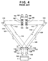
- a crane apparatus as shown, for example, in FIG. 4 is available.
- left and right traverser drums 101 and 102 as a pair, and left and right hoisting accessory drums 103 and 104 as a pair are rotatably supported on the top of a gate-shaped body frame via clutches 105 and 106, respectively, and are rotationally drivable by left and right drive motors 107 and 108 as a pair.
- First right and left traverser wire ropes 109 and 110 as a pair have an end taken up by the traverser drums 102 and 101, and have the other end connected to a right connecting portion 114 on a traverser 113 via right and left sheaves 111 and 112, respectively.
- Second right and left traverser wire ropes 115 and 116 as a pair have an end taken up by the traverser drums 102 and 101, and have the other end connected to a left connecting portion 119 on the traverser 113 via right and left sheaves 117 and 118, respectively.
- right and left hoisting accessory wire ropes 120 and 121 as a pair have an end taken up by the hoisting accessory drums 104 and 103, and have the other end passed over low-position rope pulleys 126 and 127 via right and left sheaves 122 and 123 and right and left sheaves 124 and 125 of the traverser 113, and then connected to connecting portions 128 and 129 of the traverser 113. From the rope pulleys 126 and 127, a hoisting accessory 130 capable of holding a container C is suspended. Hence, there is no need to provide rails and a trolley on the body frame. Since the weight on the body frame is reduced, the crane apparatus can be made compact and light-weight.
- the traverser 113 which supports the hoisting accessory 130, is supported by the wire ropes 109, 110, 115, 116 at the two separated connecting portions 114 and 119. Hence, sway of the hoisting accessory 130 and the suspended load C due to their inertial force is suppressed, and the work efficiency is increased.
- T W/4
- the rope tensions T 1R and T 1L of the first traverser wire ropes 109 and 110, and the rope tensions T 2R and T 2L of the second traverser wire ropes 115 and 116 vary with the angle ⁇ 1 of each of the wire ropes 109, 115 and 120, and the angle ⁇ 2 of each of the wire ropes 110, 116 and 121, namely, the traversing position of the hoisting accessory 130.
- the rope tension T of each of the hoisting accessory wire ropes 120 and 121 is constant (W/4) regardless of the traversing position of the hoisting accessory 130.
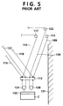
- the hoisting accessory 130 stops at a position at which rightward and leftward horizontal components of force from the hoisting accessory wire ropes 120 and 121 are balanced, as shown in FIG. 5, because the rope tension T of the hoisting accessory wire rope 120 and that of the hoisting accessory wire rope 121 are the same.
- the hoisting accessory 130 cannot be brought fully close to a crane leg 131 which supports the sheave 122, etc.
- the traversing range of the hoisting accessory 130 narrows. A full traversing function of the crane cannot be exhibited, and the work efficiency is low. If the position of the crane leg 131 is brought outward (rightward in FIG. 5), together with the sheave 122, to enlarge the traversing range of the hoisting accessory 130, the apparatus will be upsized.
- Embodiments of the present invention aim to solve the above-described problems with the earlier technology. It is an object of this invention to provide a crane apparatus designed to increase the work efficiency by enlarging the traversing range of a hoisting accessory without upsizing the apparatus.
- a crane apparatus comprising:
- the rope tension of each of the hoisting accessory wire ropes varies with the traversing position of the hoisting accessory as does the rope tension of each of the traverser wire ropes.
- the position at which the rightward and leftward horizontal components of force are balanced is more outward than in the earlier technology.
- the traversing range of the hoisting accessory widens. As noted from this, the traversing range of the hoisting accessory can be enlarged, and the work efficiency can be increased, without the need to upsize the apparatus.
- the hoisting accessory drums may be drivably connected to the drive motor, and the traverser drums may be drivably connected to the hoisting accessory drums via clutches. Consequently, the hoisting accessory drums may be driven independently to permit only the hoisting and lowering of the hoisting accessory.
- a second aspect of the invention is a crane apparatus comprising:
- the rope tension of each of the hoisting accessory wire ropes varies with the traversing position of the hoisting accessory as does the rope tension of each of the traverser wire ropes.
- the position at which the rightward and leftward horizontal components of force are balanced is more outward than in the earlier technology.
- the traversing range of the hoisting accessory widens. As noted from this, the traversing range of the hoisting accessory can be enlarged, and the work efficiency can be increased, without the need to upsize the apparatus.
- the hoisting accessory drums may be drivably connected to the drive motor, and the traverser drums may be drivably connected to the hoisting accessory drums via clutches. Consequently, the hoisting accessory drums may be driven independently to permit only the hoisting and lowering of the hoisting accessory.
- the hoisting accessory wire ropes and the suspending wire ropes may be passed over the rotating drum in opposite directions. Consequently, smooth actions can be performed.
- a third aspect of the invention is a crane apparatus comprising:
- the rope tension of each of the hoisting accessory wire ropes decreases because of the first and second rope pulleys, to reduce the rightward and leftward horizontal components of force imposed on the hoisting accessory by the hoisting accessory wire ropes.
- the position at which the rightward and leftward horizontal components of force are balanced is more outward than in the earlier technology.
- the traversing range of the hoisting accessory widens. As noted from this, the traversing range of the hoisting accessory can be enlarged, and the work efficiency can be increased, without the need to upsize the apparatus.
- the hoisting accessory drums may be drivably connected to the drive motor, and the traverser drums may be drivably connected to the hoisting accessory drums via clutches. Consequently, the hoisting accessory drums may be driven independently to permit only the hoisting and lowering of the hoisting accessory.
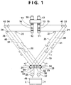
- FIG. 1 schematically shows the constitution of a crane apparatus according to a first embodiment of the invention.
- a body frame (not shown) is shaped like a gate.
- right and left traverser drums 11 and 12 as a pair, and right and left hoisting accessory drums 13 and 14 as a pair are rotatably supported via clutches 15 and 16, and are rotationally drivable by right and left drive motors 17 and 18 as a pair.
- First right and left traverser wire ropes 19 and 20 as a pair have an end taken up by the traverser drums 11 and 12, and have the other end connected to a right connecting portion 24 of a traverser 23 via right and left sheaves 21 and 22.
- Second right and left traverser wire ropes 25 and 26 as a pair have an end taken up by the traverser drums 11 and 12, and have the other end connected to a left connecting portion 29 of the traverser 23 via right and left sheaves 27 and 28.
- First right and left hoisting accessory wire ropes 31 and 32 as a pair have an end taken up by the hoisting accessory drums 13 and 14, and have the other end passed over a lower-position rope pulley 37 via right and left sheaves 33 and 34 and right sheaves 35, 36 of the traverser 23 and then connected to a connecting portion 38 of the traverser 23.
- Second right and left hoisting accessory wire ropes 39 and 40 as a pair have an end taken up by the hoisting accessory drums 13 and 14, and have the other end passed over a lower-position rope pulley 45 via right and left sheaves 41 and 42 and left sheaves 43, 44 of the traverser 23 and then connected to a connecting portion 46 of the traverser 23.
- a hoisting accessory 47 capable of holding a container C is suspended from the rope pulleys 37, 45.
- the right-hand wire ropes 19, 25, 31, 39 are parallel to each another, and the left-hand wire ropes 20, 26, 32, 40 are also parallel to each another.
- the clutches 15, 16 are disengaged, and the hoisting accessory drums 13 and 14 are rotated in opposite directions by the drive motors 17 and 18.
- the hoisting accessory wire ropes 31, 32, 39, 40 are taken up in this state, the container C held by the hoisting accessory 47 can be lifted via the rope pulleys 37, 45.
- the container C held by the hoisting accessory 47 can be lowered via the rope pulleys 37, 45.
- the clutches 15, 16 are engaged, and the respective drums 11, 12, 13 and 14 are rotated in the same direction by the drive motors 17 and 18.
- T 01R + T 01L W/4 Balance in vertical direction
- T 01R cos ⁇ 1 - T 01L cos ⁇ 2 0 Balance in horizontal direction
- T 01R + T 01R cos ⁇ 1 /cos ⁇ 2 W/4
- T 01R (W/4)cos ⁇ 2 /(cos ⁇ 1 + cos ⁇ 2 )
- T 01L (W/4)cos ⁇ 1 /(cos ⁇ 1 + cos ⁇ 2 )
- T 02R T 01R
- T 02L T 01L
- ⁇ 1 is the angle of each of the wire ropes 19, 25, 31 and 39
- ⁇ 2 is the angle of each of the wire ropes 20, 26, 32 and 40.
- the rope tensions T 01R , T 01L , T 02R and T 02L of the hoisting accessory wire ropes 31, 32, 39 and 40 vary with the traversing position of the hoisting accessory 47 (container C) as do the rope tensions T 1R , T 1L , T 2R and T 2L of the traverser wire ropes 19, 20, 25 and 26. That is, when the hoisting accessory 47 is caused to traverse most rightward, the rope angle ⁇ 1 increases, and the rope angle ⁇ 2 decreases. Thus, the tensions of the right-hand wire ropes 19, 25, 31 and 39 increase, while the tensions of the left-hand wire ropes 20, 26, 32 and 40 decrease.
- the leftward horizontal component of force on the hoisting accessory 47 becomes smaller than in the earlier technology, and the position at which the rightward and leftward horizontal components of force are balanced comes more rightward than in the earlier technology.
- the hoisting accessory 47 (container C) can be brought fully close to the crane leg as compared with the earlier technology.
- the traversing range of the hoisting accessory 47 widens, and the work efficiency of the crane can be increased without the necessity of upsizing the apparatus.
- FIG. 2 schematically shows the constitution of a crane apparatus according to a second embodiment of the invention.
- Members having the same functions as explained in the above-mentioned embodiment will be assigned the same reference numerals, and overlapping explanations will be omitted.
- right and left rotating drums 53 and 54 as a pair are supported in a suspended manner from a traverser 23 by ropes 51 and 52, as shown in FIG. 2.
- First right and left hoisting accessory wire ropes 31 and 32 have the other end passed over the right rotating drum 53 via right sheaves 35, 36 of the traverser 23, and connected to the right rotating drum 53.
- Second right and left hoisting accessory wire ropes 39 and 40 have the other end passed over the left rotating drum 54 via left sheaves 43, 44 of the traverser 23, and connected to the left rotating drum 54.
- a hoisting accessory 47 capable of holding a container C is suspended from the lower end of right and left suspending wire ropes 55 and 56 as a pair paid out from the rotating drums 53 and 54.
- the takeup directions of the hoisting accessory wire ropes 31, 32, 39, 40 and the suspending wire ropes 55, 56 on the rotating drums 53, 54 are the same. Hence, when only hoisting accessory drums (not shown) are rotated for a takeup action, the hoisting accessory wire ropes 31, 32, 39, 40 are taken up to rotate the rotating drums 53, 54. These rotating drums 53 and 54 take up the suspending wire ropes 55 and 56, whereby the container C held by the hoisting accessory 47 can be hoisted. Alternatively, the hoisting accessory wire ropes 31, 32, 39, 40 are paid out to rotate the rotating drums 53, 54.
- the rotating drums 53, 54 pay out the suspending wire ropes 55, 56, whereby the container C held by the hoisting accessory 47 can be lowered.
- the traversing action of the hoisting accessory 47 is the same as in the preceding embodiment, so that its explanation is omitted.
- the total weight of the hoisting accessory 47 and the container C be W L
- the weight of the traverser 23 be W T
- the weights of the rotating drums 53 and 54 be W D1 and W D2 .
- the rope tensions T 01R , T 01L , T 02R and T 02L of the hoisting accessory wire ropes 31, 32, 39 and 40 vary with the traversing position of the hoisting accessory 47 (container C).
- T 01R + T 01L W L /2 Balance in vertical direction
- T 01R cos ⁇ 1 - T 01L cos ⁇ 2 0 Balance in horizontal direction
- T 1R ⁇ (W L + W T + W D1 + W D2 )/2) ⁇ cos ⁇ 2 /sin( ⁇ 1 + ⁇ 2 ) - (W L /2)cos ⁇ 2 /(cos ⁇ 1 + cos ⁇ 2 )
- T 1L ⁇ (W L + W T + W D1 + W D2 )/2) ⁇ cos ⁇ 1 /sin( ⁇ 1 + ⁇ 2 ) - (W L /2)cos ⁇ 1 /(cos ⁇ 1 + cos ⁇ 2 )
- T 2R T 1R
- T 2L T 1L
- the rope tensions T 01R , T 01L , T 02R and T 02L of the hoisting accessory wire ropes 31, 32, 39 and 40 vary with the traversing position of the hoisting accessory 47 (container C) as do the rope tensions T 1R , T 1L , T 2R and T 2L of the traverser wire ropes 19, 20, 25 and 26. That is, when the hoisting accessory 47 is caused to traverse most rightward, the rope angle ⁇ 1 increases, and the rope angle ⁇ 2 decreases. Thus, the tensions of the right-hand wire ropes 19, 25, 31 and 39 increase, while the tensions of the left-hand wire ropes 20, 26, 32 and 40 decrease.
- the leftward horizontal component of force on the hoisting accessory 47 becomes smaller than in the earlier technology, and the position at which the rightward and leftward horizontal components of force are balanced comes more rightward than in the earlier technology.
- the hoisting accessory 47 (container C) can be brought fully close to the crane leg as compared with the earlier technology.
- the traversing range of the hoisting accessory 47 widens, and the work efficiency of the crane can be increased without the necessity of upsizing the apparatus.
- the right and left suspending wire ropes 55 and 56 as a pair paid out from the rotating drums 53 and 54 may be passed over the lower-position right and left rope pulleys as a pair and then connected to the traverser 23, and the hoisting accessory 47 may be suspended from the rope pulleys, as in the preceding embodiment.
- the total weight of W L of the hoisting accessory 47 and the container C can be shared between the hoisting accessory wire ropes 31, 32, 39, 40 and the traverser wire ropes 19, 20, 25, 26.
- FIG. 3 schematically shows the constitution of a crane apparatus according to a third embodiment of the invention.
- Members having the same functions as explained in the aforementioned embodiment will be assigned the same reference numerals, and overlapping explanations will be omitted.
- first right and left rope pulleys 63 and 64 as a pair are supported in a suspended manner from a traverser 23 by ropes 61 and 62, as shown in FIG. 3.
- a first hoisting accessory wire rope 31 has the other end passed round the first right rope pulley 63 via a right sheave 35 of the traverser 23, further passed over a second right rope pulley 37, and then connected to a right connecting portion 38 of the traverser 23.
- a second hoisting accessory wire rope 40 has the other end passed round the first left rope pulley 64 via a left sheave 44 of the traverser 23, further passed over a second left rope pulley 45, and then connected to a left connecting portion 46 of the traverser 23.
- a hoisting accessory 47 capable of holding a container C is suspended from the second rope pulleys 37 and 45.
- the hoisting accessory wire ropes 31, 40 are taken up, whereby the container C held by the hoisting accessory 47 can be hoisted via the first rope pulleys 63, 64 and the second rope pulleys 37, 45.
- the hoisting accessory wire ropes 31, 40 are paid out, whereby the container C held by the hoisting accessory 47 can be lowered via the first rope pulleys 63, 64 and the second rope pulleys 37, 45.
- the traversing action of the hoisting accessory 47 is the same as in the aforementioned embodiment, so that its explanation is omitted.
- the hoisting accessory wire ropes 31, 40 are connected to the traverser 23 via the first rope pulleys 63, 64 and the second rope pulleys 37, 45.
- T 1L (W/2)cos ⁇ 1 /sin( ⁇ 1 + ⁇ 2 ) - W/16
- T 2R T 1R
- T 2L T 1L
- the connecting portions 24, 29 and the sheaves 35, 36, 43, 44 of the traverser 23, the rope pulleys 37, 45, 63, 64, the first and second traverser wire ropes 19, 20, 25, 26, the first and second hoisting accessory wire ropes 31, 32, 39, 40, the traverser sheaves 21, 22, 27, 28, the hoisting accessory sheaves 33, 34, 41, 42, the rotating drums 53, 54, and the suspending wire ropes 55, 56 have been constituted as a pair composed of right and left members. However, they may be provided as a plurality of pairs.
Landscapes
- Engineering & Computer Science (AREA)
- Mechanical Engineering (AREA)
- Carriers, Traveling Bodies, And Overhead Traveling Cranes (AREA)
- Lift-Guide Devices, And Elevator Ropes And Cables (AREA)
- Jib Cranes (AREA)
Abstract
Description
- The present invention relates to a crane apparatus which is used, for example, as a transfer crane of port cargo handling equipment.
- A conventional transfer crane has a gate-shaped body frame, which can travel by a plurality of traveling wheels. On the top of the body frame, a trolley can move transversely. On the trolley, a rotationally drivable takeup drum is borne. A hoisting accessory is attached to the lower end of a plurality of load suspending wire ropes wound off from the takeup drum. Thus, as the trolley moves on the body frame, a suspended load held by the hoisting accessory can be traversed. When the takeup drum is rotationally driven at a predetermined stop position of the trolley to take up or pay out the plural wire ropes, the suspended load can be moved upwards or downwards.
- With the above-described conventional crane apparatus, rails are provided on transverse girders placed on the body frame, and the trolley is supported on the rails. In consideration of the weight of the rails, the weight of the trolley, or the weight of the suspended load imposed on the hoisting accessory, not only the transverse girders and the body frame, but also the entire crane apparatus must have great rigidity, inducing a large size and a heavy weight. When the trolley is moved laterally and stopped at a predetermined position, with the suspended load being held by the hoisting accessory, sway occurs in the hoisting accessory and the suspended load owing to an inertial force in the lateral direction. This sway does not settle quickly. To prevent sway of the hoisting accessory and the suspended load when the trolley stops, the trolley has to be moved at a slow speed. Since a long time is required for work, the work efficiency is low.
- As a solution to the above-mentioned problem, a crane apparatus as shown, for example, in FIG. 4 is available. In this conventional crane apparatus, as shown in FIG. 4, left and
right traverser drums accessory drums clutches right drive motors traverser wire ropes traverser drums portion 114 on atraverser 113 via right andleft sheaves traverser wire ropes traverser drums portion 119 on thetraverser 113 via right andleft sheaves accessory wire ropes accessory drums position rope pulleys left sheaves left sheaves 124 and 125 of thetraverser 113, and then connected to connectingportions 128 and 129 of thetraverser 113. From therope pulleys accessory 130 capable of holding a container C is suspended. Hence, there is no need to provide rails and a trolley on the body frame. Since the weight on the body frame is reduced, the crane apparatus can be made compact and light-weight. Besides, thetraverser 113, which supports the hoistingaccessory 130, is supported by thewire ropes portions accessory 130 and the suspended load C due to their inertial force is suppressed, and the work efficiency is increased. - In the conventional crane apparatus described above, let the weight of the hoisting
accessory 130 and the suspended load C be W. Then, the rope tension T of the hoistingaccessory wire ropes traverser wire ropes traverser wire ropes wire ropes wire ropes - In other words, the rope tensions T1R and T1L of the first
traverser wire ropes traverser wire ropes wire ropes wire ropes accessory 130. Whereas the rope tension T of each of the hoistingaccessory wire ropes accessory 130. - Under these situations, when the hoisting
accessory 130 is traversed most rightward, the hoistingaccessory 130 stops at a position at which rightward and leftward horizontal components of force from the hoistingaccessory wire ropes accessory wire rope 120 and that of the hoistingaccessory wire rope 121 are the same. Thus, the hoistingaccessory 130 cannot be brought fully close to acrane leg 131 which supports thesheave 122, etc. As a result, the traversing range of the hoistingaccessory 130 narrows. A full traversing function of the crane cannot be exhibited, and the work efficiency is low. If the position of thecrane leg 131 is brought outward (rightward in FIG. 5), together with thesheave 122, to enlarge the traversing range of the hoistingaccessory 130, the apparatus will be upsized. - Embodiments of the present invention aim to solve the above-described problems with the earlier technology. It is an object of this invention to provide a crane apparatus designed to increase the work efficiency by enlarging the traversing range of a hoisting accessory without upsizing the apparatus.
- According to a first aspect of the present invention there is provided a crane apparatus comprising:
- a body frame;
- traverser drums and hoisting accessory drums rotatably mounted on the body frame and normally and reversely rotatable by a drive motor;
- a traverser having right and left connecting portions as a pair, and right and left sheaves as a pair;
- right and left rope pulleys as a pair positioned below the traverser;
- first right and left traverser wire ropes as a pair having an end taken up by the traverser drums, and having the other end connected to the right connecting portion of the traverser;
- second right and left traverser wire ropes as a pair having an end taken up by the traverser drums, and having the other end connected to the left connecting portion of the traverser;
- first right and left hoisting accessory wire ropes as a pair having an end taken up by the hoisting accessory drums, and having the other end passed over the right rope pulley via the right sheave of the traverser and then connected to the traverser;
- second right and left hoisting accessory wire ropes as a pair having an end taken up by the hoisting accessory drums, and having the other end passed over the left rope pulley via the left sheave of the traverser and then connected to the traverser;
- right and left traverser sheaves as a pair and right and left hoisting accessory sheaves as a pair for guiding the right-hand wire ropes to be parallel and the left-hand wire ropes to be parallel; and
- a hoisting accessory capable of attaching and detaching a load thereto and therefrom, and suspended from the right and left rope pulleys.
-
- Thus, the rope tension of each of the hoisting accessory wire ropes varies with the traversing position of the hoisting accessory as does the rope tension of each of the traverser wire ropes. When the hoisting accessory comes to a terminal area in a traversing direction, the position at which the rightward and leftward horizontal components of force are balanced is more outward than in the earlier technology. Thus, the traversing range of the hoisting accessory widens. As noted from this, the traversing range of the hoisting accessory can be enlarged, and the work efficiency can be increased, without the need to upsize the apparatus.
- In the crane apparatus as the first aspect of the invention, the hoisting accessory drums may be drivably connected to the drive motor, and the traverser drums may be drivably connected to the hoisting accessory drums via clutches. Consequently, the hoisting accessory drums may be driven independently to permit only the hoisting and lowering of the hoisting accessory.
- A second aspect of the invention is a crane apparatus comprising:
- a body frame;
- traverser drums and hoisting accessory drums rotatably mounted on the body frame and normally and reversely rotatable by a drive motor;
- a traverser having right and left connecting portions as a pair, and right and left sheaves as a pair;
- right and left rotating drums as a pair suspended from the traverser;
- first right and left traverser wire ropes as a pair having an end taken up by the traverser drums, and having the other end connected to the right connecting portion of the traverser;
- second right and left traverser wire ropes as a pair having an end taken up by the traverser drums, and having the other end connected to the left connecting portion of the traverser;
- first right and left hoisting accessory wire ropes as a pair having an end taken up by the hoisting accessory drums, and having the other end passed over the right rotating drum via the right sheave of the traverser;
- second right and left hoisting accessory wire ropes as a pair having an end taken up by the hoisting accessory drums, and having the other end passed over the left rotating drum via the left sheave of the traverser;
- right and left traverser sheaves as a pair and right and left hoisting accessory sheaves as a pair for guiding the right-hand wire ropes to be parallel and the left-hand wire ropes to be parallel; and
- a hoisting accessory capable of attaching and detaching a load thereto and therefrom, and connected to right and left suspending wire ropes as a pair paid out from the right and left rotating drums.
-
- Thus, the rope tension of each of the hoisting accessory wire ropes varies with the traversing position of the hoisting accessory as does the rope tension of each of the traverser wire ropes. When the hoisting accessory comes to a terminal area in a traversing direction, the position at which the rightward and leftward horizontal components of force are balanced is more outward than in the earlier technology. Thus, the traversing range of the hoisting accessory widens. As noted from this, the traversing range of the hoisting accessory can be enlarged, and the work efficiency can be increased, without the need to upsize the apparatus.
- In the crane apparatus as the second aspect of the invention, the hoisting accessory drums may be drivably connected to the drive motor, and the traverser drums may be drivably connected to the hoisting accessory drums via clutches. Consequently, the hoisting accessory drums may be driven independently to permit only the hoisting and lowering of the hoisting accessory.
- In the crane apparatus as the second aspect of the invention, moreover, the hoisting accessory wire ropes and the suspending wire ropes may be passed over the rotating drum in opposite directions. Consequently, smooth actions can be performed.
- A third aspect of the invention is a crane apparatus comprising:
- a body frame;
- traverser drums and hoisting accessory drums rotatably mounted on the body frame and normally and reversely rotatable by a drive motor;
- a traverser having right and left connecting portions as a pair, and right and left sheaves as a pair;
- first right and left rope pulleys as a pair suspended from the traverser;
- second right and left rope pulleys as a pair positioned below the first right and left rope pulleys;
- first right and left traverser wire ropes as a pair having an end taken up by the traverser drums, and having the other end connected to the right connecting portion of the traverser;
- second right and left traverser wire ropes as a pair having an end taken up by the traverser drums, and having the other end connected to the left connecting portion of the traverser;
- a first hoisting accessory wire rope having an end taken up by the hoisting accessory drum, and having the other end passed over the first and second right rope pulleys via the right sheave of the traverser and then connected to the traverser;
- a second hoisting accessory wire rope having an end taken up by the hoisting accessory drum, and having the other end passed over the first and second left rope pulleys via the left sheave of the traverser and then connected to the traverser;
- right and left traverser sheaves as a pair and right and left hoisting accessory sheaves as a pair for guiding the right-hand wire ropes to be parallel and the left-hand wire ropes to be parallel; and
- a hoisting accessory capable of attaching and detaching a load thereto and therefrom, and suspended from the second right and left rope pulleys.
-
- Thus, the rope tension of each of the hoisting accessory wire ropes decreases because of the first and second rope pulleys, to reduce the rightward and leftward horizontal components of force imposed on the hoisting accessory by the hoisting accessory wire ropes. As a result, when the hoisting accessory comes to a terminal area in a traversing direction, the position at which the rightward and leftward horizontal components of force are balanced is more outward than in the earlier technology. Thus, the traversing range of the hoisting accessory widens. As noted from this, the traversing range of the hoisting accessory can be enlarged, and the work efficiency can be increased, without the need to upsize the apparatus.
- In the crane apparatus as the third aspect of the invention, the hoisting accessory drums may be drivably connected to the drive motor, and the traverser drums may be drivably connected to the hoisting accessory drums via clutches. Consequently, the hoisting accessory drums may be driven independently to permit only the hoisting and lowering of the hoisting accessory.
- The above and other objects, features and advantages of the present invention will become more apparent from the following description taken in connection with the accompanying drawings, in which:
- FIG. 1 is a schematic constitution drawing of a crane apparatus according to a first embodiment of the present invention;
- FIG. 2 is a schematic constitution drawing of a crane apparatus according to a second embodiment of the invention;
- FIG. 3 is a schematic constitution drawing of a crane apparatus according to a third embodiment of the invention;
- FIG. 4 is a schematic constitution drawing of a conventional crane apparatus; and
- FIG. 5 is a schematic view of the conventional crane apparatus during a traversing action.
-
- Embodiments of the present invention will now be described in detail with reference to the accompanying drawings.
- FIG. 1 schematically shows the constitution of a crane apparatus according to a first embodiment of the invention.
- In the crane apparatus of the present embodiment, as shown in FIG. 1, a body frame (not shown) is shaped like a gate. On the top of the body frame, right and left traverser drums 11 and 12 as a pair, and right and left hoisting
accessory drums clutches drive motors traverser wire ropes right connecting portion 24 of atraverser 23 via right and leftsheaves traverser wire ropes portion 29 of thetraverser 23 via right and leftsheaves - First right and left hoisting
accessory wire ropes accessory drums position rope pulley 37 via right and leftsheaves right sheaves traverser 23 and then connected to a connectingportion 38 of thetraverser 23. Second right and left hoistingaccessory wire ropes accessory drums position rope pulley 45 via right and leftsheaves sheaves traverser 23 and then connected to a connectingportion 46 of thetraverser 23. A hoisting accessory 47 capable of holding a container C is suspended from the rope pulleys 37, 45. The right-hand wire ropes hand wire ropes - The
clutches accessory drums drive motors accessory wire ropes accessory wire ropes clutches respective drums drive motors accessory wire ropes traverser wire ropes accessory wire ropes traverser wire ropes traverser 23. On the other hand, when the hoistingaccessory wire ropes traverser wire ropes accessory wire ropes traverser wire ropes traverser 23. - In the crane apparatus of the present embodiment, let the total weight of the hoisting accessory 47 and the container C be W. Then, the rope tensions T01R, T01L, T02R and T02L of the hoisting
accessory wire ropes
In the above equations, 1 is the angle of each of thewire ropes wire ropes - The rope tensions T1R, T1L, T2R and T2L of the
traverser wire ropes - As described above, the rope tensions T01R, T01L, T02R and T02L of the hoisting
accessory wire ropes traverser wire ropes hand wire ropes hand wire ropes - FIG. 2 schematically shows the constitution of a crane apparatus according to a second embodiment of the invention. Members having the same functions as explained in the above-mentioned embodiment will be assigned the same reference numerals, and overlapping explanations will be omitted.
- In the crane apparatus of the present embodiment, right and left
rotating drums traverser 23 byropes accessory wire ropes rotating drum 53 viaright sheaves traverser 23, and connected to the rightrotating drum 53. Second right and left hoistingaccessory wire ropes rotating drum 54 vialeft sheaves traverser 23, and connected to the leftrotating drum 54. A hoisting accessory 47 capable of holding a container C is suspended from the lower end of right and left suspendingwire ropes 55 and 56 as a pair paid out from therotating drums accessory wire ropes wire ropes 55, 56 on therotating drums accessory wire ropes rotating drums rotating drums wire ropes 55 and 56, whereby the container C held by the hoisting accessory 47 can be hoisted. Alternatively, the hoistingaccessory wire ropes rotating drums wire ropes 55, 56, whereby the container C held by the hoisting accessory 47 can be lowered. The traversing action of the hoisting accessory 47 is the same as in the preceding embodiment, so that its explanation is omitted. - In the crane apparatus of the present embodiment, too, let the total weight of the hoisting accessory 47 and the container C be WL, the weight of the
traverser 23 be WT, and the weights of therotating drums accessory wire ropes - The rope tensions T1R, T1L, T2R and T2L of the
traverser wire ropes - Based on the equations (16) and (18), the same calculations as in the aforementioned embodiment are made, giving:
- As described above, the rope tensions T01R, T01L, T02R and T02L of the hoisting
accessory wire ropes traverser wire ropes hand wire ropes hand wire ropes - In the present embodiment, the right and left suspending
wire ropes 55 and 56 as a pair paid out from therotating drums traverser 23, and the hoisting accessory 47 may be suspended from the rope pulleys, as in the preceding embodiment. In this case, the total weight of WL of the hoisting accessory 47 and the container C can be shared between the hoistingaccessory wire ropes traverser wire ropes - FIG. 3 schematically shows the constitution of a crane apparatus according to a third embodiment of the invention. Members having the same functions as explained in the aforementioned embodiment will be assigned the same reference numerals, and overlapping explanations will be omitted.
- In the crane apparatus of the present embodiment, first right and left rope pulleys 63 and 64 as a pair are supported in a suspended manner from a
traverser 23 byropes accessory wire rope 31 has the other end passed round the firstright rope pulley 63 via aright sheave 35 of thetraverser 23, further passed over a secondright rope pulley 37, and then connected to aright connecting portion 38 of thetraverser 23. A second hoistingaccessory wire rope 40 has the other end passed round the firstleft rope pulley 64 via aleft sheave 44 of thetraverser 23, further passed over a secondleft rope pulley 45, and then connected to a left connectingportion 46 of thetraverser 23. A hoisting accessory 47 capable of holding a container C is suspended from the second rope pulleys 37 and 45. Hence, when only hoisting accessory drums (not shown) are rotated for a takeup action, the hoistingaccessory wire ropes accessory wire ropes - In the crane apparatus of the present embodiment, the hoisting
accessory wire ropes traverser 23 via the first rope pulleys 63, 64 and the second rope pulleys 37, 45. Thus, rightward and leftward horizontal components of force, which the hoistingaccessory wire ropes - As described above, since the rope tensions T of the hoisting
accessory wire ropes traverser wire ropes - In the foregoing respective embodiments, the connecting
portions sheaves traverser 23, the rope pulleys 37, 45, 63, 64, the first and secondtraverser wire ropes accessory wire ropes accessory sheaves rotating drums wire ropes 55, 56 have been constituted as a pair composed of right and left members. However, they may be provided as a plurality of pairs. - The invention being thus described, it will be obvious that the same may be varied in many ways. Such variations are not to be regarded as a departure from the spirit and scope of the invention, and all such modifications as would be obvious to one skilled in the art are intended to be included within the scope of the following claims.
Claims (7)
- A crane apparatus comprising:a body frame;traverser drums and hoisting accessory drums rotatably mounted on the body frame and normally and reversely rotatable by a drive motor;a traverser having right and left connecting portions as a pair, and right and left sheaves as a pair;right and left rope pulleys as a pair positioned below the traverser;first right and left traverser wire ropes as a pair having an end taken up by the traverser drums, and having the other end connected to the right connecting portion of the traverser;second right and left traverser wire ropes as a pair having an end taken up by the traverser drums, and having the other end connected to the left connecting portion of the traverser;first right and left hoisting accessory wire ropes as a pair having an end taken up by the hoisting accessory drums, and having the other end passed over the right rope pulley via the right sheave of the traverser and then connected to the traverser;second right and left hoisting accessory wire ropes as a pair having an end taken up by the hoisting accessory drums, and having the other end passed over the left rope pulley via the left sheave of the traverser and then connected to the traverser;right and left traverser sheaves as a pair and right and left hoisting accessory sheaves as a pair for guiding the right-hand wire ropes to be parallel and the left-hand wire ropes to be parallel; anda hoisting accessory capable of attaching and detaching a load thereto and therefrom, and suspended from the right and left rope pulleys.
- The crane apparatus of claim 1, wherein the hoisting accessory drums are drivably connected to the drive motor, and the traverser drums are drivably connected to the hoisting accessory drums via clutches.
- A crane apparatus comprising:a body frame;traverser drums and hoisting accessory drums rotatably mounted on the body frame and normally and reversely rotatable by a drive motor;a traverser having right and left connecting portions as a pair, and right and left sheaves as a pair;right and left rotating drums as a pair suspended from the traverser;first right and left traverser wire ropes as a pair having an end taken up by the traverser drums, and having the other end connected to the right connecting portion of the traverser;second right and left traverser wire ropes as a pair having an end taken up by the traverser drums, and having the other end connected to the left connecting portion of the traverser;first right and left hoisting accessory wire ropes as a pair having an end taken up by the hoisting accessory drums, and having the other end passed over the right rotating drum via the right sheave of the traverser;second right and left hoisting accessory wire ropes as a pair having an end taken up by the hoisting accessory drums, and having the other end passed over the left rotating drum via the left sheave of the traverser;right and left traverser sheaves as a pair and right and left hoisting accessory sheaves as a pair for guiding the right-hand wire ropes to be parallel and the left-hand wire ropes to be parallel; anda hoisting accessory capable of attaching and detaching a load thereto and therefrom, and connected to right and left suspending wire ropes as a pair paid out from the right and left rotating drums.
- The crane apparatus of claim 3, wherein the hoisting accessory drums are drivably connected to the drive motor, and the traverser drums are drivably connected to the hoisting accessory drums via clutches.
- The crane apparatus of claim 3, wherein the hoisting accessory wire ropes and the suspending wire rope are passed over the rotating drum in opposite directions.
- A crane apparatus comprising:a body frame;traverser drums and hoisting accessory drums rotatably mounted on the body frame and normally and reversely rotatable by a drive motor;a traverser having right and left connecting portions as a pair, and right and left sheaves as a pair;first right and left rope pulleys as a pair suspended from the traverser;second right and left rope pulleys as a pair positioned below the first right and left rope pulleys;first right and left traverser wire ropes as a pair having an end taken up by the traverser drums, and having the other end connected to the right connecting portion of the traverser;second right and left traverser wire ropes as a pair having an end taken up by the traverser drums, and having the other end connected to the left connecting portion of the traverser;a first hoisting accessory wire rope having an end taken up by the hoisting accessory drum, and having the other end passed over the first and second right rope pulleys via the right sheave of the traverser and then connected to the traverser;a second hoisting accessory wire rope having an end taken up by the hoisting accessory drum, and having the other end passed over the first and second left rope pulleys via the left sheave of the traverser and then connected to the traverser;right and left traverser sheaves as a pair and right and left hoisting accessory sheaves as a pair for guiding the right-hand wire ropes to be parallel and the left-hand wire ropes to be parallel; anda hoisting accessory capable of attaching and detaching a load thereto and therefrom, and suspended from the second right and left rope pulleys.
- The crane apparatus of claim 6, wherein the hoisting accessory drums are drivably connected to the drive motor, and the traverser drums are drivably connected to the hoisting accessory drums via clutches.
Applications Claiming Priority (4)
| Application Number | Priority Date | Filing Date | Title |
|---|---|---|---|
| JP22818499 | 1999-08-12 | ||
| JP22818499 | 1999-08-12 | ||
| JP2000003258 | 2000-01-12 | ||
| JP2000003258A JP2001114492A (en) | 1999-08-12 | 2000-01-12 | Crane device |
Publications (2)
| Publication Number | Publication Date |
|---|---|
| EP1076032A1 true EP1076032A1 (en) | 2001-02-14 |
| EP1076032B1 EP1076032B1 (en) | 2004-09-15 |
Family
ID=26528101
Family Applications (1)
| Application Number | Title | Priority Date | Filing Date |
|---|---|---|---|
| EP00305001A Expired - Lifetime EP1076032B1 (en) | 1999-08-12 | 2000-06-13 | Crane apparatus |
Country Status (7)
| Country | Link |
|---|---|
| US (1) | US6343702B1 (en) |
| EP (1) | EP1076032B1 (en) |
| JP (1) | JP2001114492A (en) |
| KR (1) | KR100378967B1 (en) |
| DE (1) | DE60013714T2 (en) |
| SG (1) | SG91286A1 (en) |
| TW (1) | TW553885B (en) |
Cited By (1)
| Publication number | Priority date | Publication date | Assignee | Title |
|---|---|---|---|---|
| EP1273549A1 (en) * | 2001-07-04 | 2003-01-08 | EISENMANN MASCHINENBAU KG (Komplementär: EISENMANN-Stiftung) | Lifting device |
Families Citing this family (10)
| Publication number | Priority date | Publication date | Assignee | Title |
|---|---|---|---|---|
| CN1319844C (en) * | 2003-05-21 | 2007-06-06 | 上海振华港口机械(集团)股份有限公司 | Bidirectional swing-preventing system for crane |
| KR100578077B1 (en) * | 2004-06-23 | 2006-05-10 | 현대삼호중공업 주식회사 | Anti-sway apparatus for container transportation |
| JP5738977B2 (en) | 2010-04-01 | 2015-06-24 | パー システムズ, インコーポレイテッド | Tension truss mast |
| GB2495958A (en) * | 2011-10-26 | 2013-05-01 | Core Pd Ltd | Tension cable robot |
| US9834418B2 (en) | 2012-09-21 | 2017-12-05 | Par Systems, Inc. | Boat deployment assembly and method |
| US10494233B2 (en) | 2013-02-06 | 2019-12-03 | Par Systems, Llc | Relocatable fine motion positioner assembly on an overhead crane |
| CN103287975B (en) * | 2013-04-24 | 2015-09-23 | 交通运输部水运科学研究所 | Hoisting crane compound motion control method |
| KR101511851B1 (en) * | 2013-10-11 | 2015-04-17 | 신정훈 | Grill lift of zenith-type air conditioner |
| KR101883383B1 (en) | 2016-03-24 | 2018-07-30 | 주식회사 포스코 | Rope coupler |
| US11446812B2 (en) * | 2017-12-22 | 2022-09-20 | Marchesini Group S.P.A. | Cable-driven robot |
Citations (2)
| Publication number | Priority date | Publication date | Assignee | Title |
|---|---|---|---|---|
| FR2455560A1 (en) * | 1979-04-30 | 1980-11-28 | Tax Hans | Electromotor with encapsulated thermal protection switch - is built into slot closure piece of stator and rotor winding slots |
| WO1999028230A1 (en) * | 1997-12-03 | 1999-06-10 | Mitsubishi Heavy Industries, Ltd. | Crane apparatus |
Family Cites Families (4)
| Publication number | Priority date | Publication date | Assignee | Title |
|---|---|---|---|---|
| US4069921A (en) * | 1976-01-30 | 1978-01-24 | Harnischfeger Corporation | Overhead crane including a single failure proof hoist |
| US4883184A (en) * | 1986-05-23 | 1989-11-28 | Albus James S | Cable arrangement and lifting platform for stabilized load lifting |
| US4949854A (en) * | 1988-12-09 | 1990-08-21 | Harnischfeger Corporation | Anti-sway crane reeving apparatus |
| AU4275497A (en) * | 1996-11-07 | 1998-05-14 | Ishikawajima-Harima Jukogyo Kabushiki Kaisha | Container crane |
-
2000
- 2000-01-12 JP JP2000003258A patent/JP2001114492A/en not_active Withdrawn
- 2000-06-03 TW TW089110892A patent/TW553885B/en not_active IP Right Cessation
- 2000-06-08 SG SG200003210A patent/SG91286A1/en unknown
- 2000-06-13 DE DE60013714T patent/DE60013714T2/en not_active Expired - Fee Related
- 2000-06-13 EP EP00305001A patent/EP1076032B1/en not_active Expired - Lifetime
- 2000-06-13 US US09/592,931 patent/US6343702B1/en not_active Expired - Fee Related
- 2000-08-09 KR KR10-2000-0046054A patent/KR100378967B1/en not_active Expired - Fee Related
Patent Citations (2)
| Publication number | Priority date | Publication date | Assignee | Title |
|---|---|---|---|---|
| FR2455560A1 (en) * | 1979-04-30 | 1980-11-28 | Tax Hans | Electromotor with encapsulated thermal protection switch - is built into slot closure piece of stator and rotor winding slots |
| WO1999028230A1 (en) * | 1997-12-03 | 1999-06-10 | Mitsubishi Heavy Industries, Ltd. | Crane apparatus |
Cited By (1)
| Publication number | Priority date | Publication date | Assignee | Title |
|---|---|---|---|---|
| EP1273549A1 (en) * | 2001-07-04 | 2003-01-08 | EISENMANN MASCHINENBAU KG (Komplementär: EISENMANN-Stiftung) | Lifting device |
Also Published As
| Publication number | Publication date |
|---|---|
| US6343702B1 (en) | 2002-02-05 |
| TW553885B (en) | 2003-09-21 |
| SG91286A1 (en) | 2002-09-17 |
| KR20010021248A (en) | 2001-03-15 |
| DE60013714T2 (en) | 2005-12-08 |
| JP2001114492A (en) | 2001-04-24 |
| HK1030590A1 (en) | 2001-05-11 |
| KR100378967B1 (en) | 2003-04-08 |
| EP1076032B1 (en) | 2004-09-15 |
| DE60013714D1 (en) | 2004-10-21 |
Similar Documents
| Publication | Publication Date | Title |
|---|---|---|
| EP1076032B1 (en) | Crane apparatus | |
| US6345724B1 (en) | Crane apparatus | |
| EP2962977B1 (en) | Gantry crane for handling containers | |
| JPWO1999028230A1 (en) | Crane equipment | |
| CN210655862U (en) | Wire rope winding system applied to traditional quay crane external operation trolley | |
| US6651961B1 (en) | Multiple load blocks for a crane | |
| CN112479032A (en) | Gantry crane | |
| JP6380870B2 (en) | crane | |
| JP5555440B2 (en) | Quay crane | |
| HK1030590B (en) | Crane apparatus | |
| JP3031548B1 (en) | Container crane container lifting equipment position adjustment device | |
| CN112374351B (en) | Lifting appliance adjusting device and crane | |
| CN210214589U (en) | Anti-swing device and crane | |
| CN223906394U (en) | Bidirectional anti-rolling lifting mechanism of crane | |
| EP0652846B1 (en) | Trolley | |
| RU2827254C1 (en) | Stabilizing suspension for cargoes moved by crane | |
| US4181291A (en) | Apparatus for supporting and controlling the grabbing device of hoisting gear | |
| CN119429968A (en) | A two-way anti-sway lifting mechanism for crane | |
| JP3937362B2 (en) | Mobile crane | |
| CN101830396B (en) | Trolley for crane | |
| JP3305256B2 (en) | Spreader cable winding device for container crane | |
| JP2647500B2 (en) | Container guide device for shuttle trolley in container crane | |
| JPH0512224Y2 (en) | ||
| JP2634476B2 (en) | Crane lifting gear shift device | |
| CN117228550A (en) | A small prefabricated component hoisting device |
Legal Events
| Date | Code | Title | Description |
|---|---|---|---|
| PUAI | Public reference made under article 153(3) epc to a published international application that has entered the european phase |
Free format text: ORIGINAL CODE: 0009012 |
|
| 17P | Request for examination filed |
Effective date: 20000623 |
|
| AK | Designated contracting states |
Kind code of ref document: A1 Designated state(s): DE GB IT |
|
| AX | Request for extension of the european patent |
Free format text: AL;LT;LV;MK;RO;SI |
|
| AKX | Designation fees paid |
Free format text: DE GB IT |
|
| 17Q | First examination report despatched |
Effective date: 20030626 |
|
| GRAP | Despatch of communication of intention to grant a patent |
Free format text: ORIGINAL CODE: EPIDOSNIGR1 |
|
| GRAS | Grant fee paid |
Free format text: ORIGINAL CODE: EPIDOSNIGR3 |
|
| GRAA | (expected) grant |
Free format text: ORIGINAL CODE: 0009210 |
|
| RIN1 | Information on inventor provided before grant (corrected) |
Inventor name: OKADA, TAKASHI,C/O MITSUBISHI HEAVY INDUSTRIES LT Inventor name: YASUNAGA, IKKO,C/O MITSUBISHI HEAVY INDUSTRIES LT Inventor name: MASUMOTO, SHINICHI,C/O MITSUBISHI HEAVY INDUSTRIE Inventor name: HIRANO, TATSUYA,C/O MITSUBISHI HEAVY INDUSTRIES L Inventor name: CHIKURA, TAKASHI,C/O MITSUBISHI HEAVY INDUSTRIES Inventor name: ICHIKIZAKI, TETSUO,C/O MITSUBISHI HEAVY INDUSTRIE Inventor name: ABIRU, HISANORI,C/O MITSUBISHI HEAVY INDUSTRIES L Inventor name: MASUMOTO, MASANORI,C/O MITSUBISHI HEAVY INDUSTRIE |
|
| AK | Designated contracting states |
Kind code of ref document: B1 Designated state(s): DE GB IT |
|
| PG25 | Lapsed in a contracting state [announced via postgrant information from national office to epo] |
Ref country code: IT Free format text: LAPSE BECAUSE OF FAILURE TO SUBMIT A TRANSLATION OF THE DESCRIPTION OR TO PAY THE FEE WITHIN THE PRESCRIBED TIME-LIMIT;WARNING: LAPSES OF ITALIAN PATENTS WITH EFFECTIVE DATE BEFORE 2007 MAY HAVE OCCURRED AT ANY TIME BEFORE 2007. THE CORRECT EFFECTIVE DATE MAY BE DIFFERENT FROM THE ONE RECORDED. Effective date: 20040915 |
|
| REG | Reference to a national code |
Ref country code: GB Ref legal event code: FG4D |
|
| REF | Corresponds to: |
Ref document number: 60013714 Country of ref document: DE Date of ref document: 20041021 Kind code of ref document: P |
|
| REG | Reference to a national code |
Ref country code: HK Ref legal event code: GR Ref document number: 1030590 Country of ref document: HK |
|
| PGFP | Annual fee paid to national office [announced via postgrant information from national office to epo] |
Ref country code: GB Payment date: 20050531 Year of fee payment: 6 |
|
| PLBE | No opposition filed within time limit |
Free format text: ORIGINAL CODE: 0009261 |
|
| STAA | Information on the status of an ep patent application or granted ep patent |
Free format text: STATUS: NO OPPOSITION FILED WITHIN TIME LIMIT |
|
| PGFP | Annual fee paid to national office [announced via postgrant information from national office to epo] |
Ref country code: DE Payment date: 20050829 Year of fee payment: 6 |
|
| 26N | No opposition filed |
Effective date: 20050616 |
|
| PG25 | Lapsed in a contracting state [announced via postgrant information from national office to epo] |
Ref country code: GB Free format text: LAPSE BECAUSE OF NON-PAYMENT OF DUE FEES Effective date: 20060613 |
|
| PG25 | Lapsed in a contracting state [announced via postgrant information from national office to epo] |
Ref country code: DE Free format text: LAPSE BECAUSE OF NON-PAYMENT OF DUE FEES Effective date: 20070103 |
|
| GBPC | Gb: european patent ceased through non-payment of renewal fee |
Effective date: 20060613 |