EP1075926A1 - End finishing of plastic optical fibers using laser ablation - Google Patents
End finishing of plastic optical fibers using laser ablation Download PDFInfo
- Publication number
- EP1075926A1 EP1075926A1 EP00306066A EP00306066A EP1075926A1 EP 1075926 A1 EP1075926 A1 EP 1075926A1 EP 00306066 A EP00306066 A EP 00306066A EP 00306066 A EP00306066 A EP 00306066A EP 1075926 A1 EP1075926 A1 EP 1075926A1
- Authority
- EP
- European Patent Office
- Prior art keywords
- optical fiber
- light
- optical
- fiber
- finishing
- Prior art date
- Legal status (The legal status is an assumption and is not a legal conclusion. Google has not performed a legal analysis and makes no representation as to the accuracy of the status listed.)
- Granted
Links
- 239000013308 plastic optical fiber Substances 0.000 title abstract description 12
- 238000000608 laser ablation Methods 0.000 title 1
- 239000013307 optical fiber Substances 0.000 claims abstract description 35
- 230000003287 optical effect Effects 0.000 claims abstract description 16
- 238000000034 method Methods 0.000 claims abstract description 15
- 230000000873 masking effect Effects 0.000 claims 2
- 239000011521 glass Substances 0.000 claims 1
- 239000000835 fiber Substances 0.000 abstract description 10
- 239000000463 material Substances 0.000 description 6
- 238000003780 insertion Methods 0.000 description 5
- 230000037431 insertion Effects 0.000 description 5
- VYPSYNLAJGMNEJ-UHFFFAOYSA-N Silicium dioxide Chemical compound O=[Si]=O VYPSYNLAJGMNEJ-UHFFFAOYSA-N 0.000 description 3
- 238000002679 ablation Methods 0.000 description 2
- 238000010521 absorption reaction Methods 0.000 description 2
- 239000004033 plastic Substances 0.000 description 2
- 229920003023 plastic Polymers 0.000 description 2
- 238000005498 polishing Methods 0.000 description 2
- 229920003229 poly(methyl methacrylate) Polymers 0.000 description 2
- 239000004926 polymethyl methacrylate Substances 0.000 description 2
- 230000005540 biological transmission Effects 0.000 description 1
- 238000004519 manufacturing process Methods 0.000 description 1
- -1 poly(butenyl vinyl ether Chemical compound 0.000 description 1
- 239000004417 polycarbonate Substances 0.000 description 1
- 229920000515 polycarbonate Polymers 0.000 description 1
- 239000010453 quartz Substances 0.000 description 1
- 239000000377 silicon dioxide Substances 0.000 description 1
Images
Classifications
-
- G—PHYSICS
- G02—OPTICS
- G02B—OPTICAL ELEMENTS, SYSTEMS OR APPARATUS
- G02B6/00—Light guides; Structural details of arrangements comprising light guides and other optical elements, e.g. couplings
- G02B6/24—Coupling light guides
- G02B6/25—Preparing the ends of light guides for coupling, e.g. cutting
-
- B—PERFORMING OPERATIONS; TRANSPORTING
- B29—WORKING OF PLASTICS; WORKING OF SUBSTANCES IN A PLASTIC STATE IN GENERAL
- B29C—SHAPING OR JOINING OF PLASTICS; SHAPING OF MATERIAL IN A PLASTIC STATE, NOT OTHERWISE PROVIDED FOR; AFTER-TREATMENT OF THE SHAPED PRODUCTS, e.g. REPAIRING
- B29C67/00—Shaping techniques not covered by groups B29C39/00 - B29C65/00, B29C70/00 or B29C73/00
- B29C67/0044—Shaping techniques not covered by groups B29C39/00 - B29C65/00, B29C70/00 or B29C73/00 for shaping edges or extremities
-
- B—PERFORMING OPERATIONS; TRANSPORTING
- B29—WORKING OF PLASTICS; WORKING OF SUBSTANCES IN A PLASTIC STATE IN GENERAL
- B29D—PRODUCING PARTICULAR ARTICLES FROM PLASTICS OR FROM SUBSTANCES IN A PLASTIC STATE
- B29D11/00—Producing optical elements, e.g. lenses or prisms
- B29D11/00663—Production of light guides
-
- G—PHYSICS
- G02—OPTICS
- G02B—OPTICAL ELEMENTS, SYSTEMS OR APPARATUS
- G02B6/00—Light guides; Structural details of arrangements comprising light guides and other optical elements, e.g. couplings
- G02B6/24—Coupling light guides
- G02B6/255—Splicing of light guides, e.g. by fusion or bonding
- G02B6/2552—Splicing of light guides, e.g. by fusion or bonding reshaping or reforming of light guides for coupling using thermal heating, e.g. tapering, forming of a lens on light guide ends
-
- B—PERFORMING OPERATIONS; TRANSPORTING
- B29—WORKING OF PLASTICS; WORKING OF SUBSTANCES IN A PLASTIC STATE IN GENERAL
- B29C—SHAPING OR JOINING OF PLASTICS; SHAPING OF MATERIAL IN A PLASTIC STATE, NOT OTHERWISE PROVIDED FOR; AFTER-TREATMENT OF THE SHAPED PRODUCTS, e.g. REPAIRING
- B29C2791/00—Shaping characteristics in general
- B29C2791/004—Shaping under special conditions
- B29C2791/009—Using laser
-
- B—PERFORMING OPERATIONS; TRANSPORTING
- B29—WORKING OF PLASTICS; WORKING OF SUBSTANCES IN A PLASTIC STATE IN GENERAL
- B29L—INDEXING SCHEME ASSOCIATED WITH SUBCLASS B29C, RELATING TO PARTICULAR ARTICLES
- B29L2011/00—Optical elements, e.g. lenses, prisms
- B29L2011/0075—Light guides, optical cables
-
- G—PHYSICS
- G02—OPTICS
- G02B—OPTICAL ELEMENTS, SYSTEMS OR APPARATUS
- G02B6/00—Light guides; Structural details of arrangements comprising light guides and other optical elements, e.g. couplings
- G02B6/02—Optical fibres with cladding with or without a coating
- G02B6/02033—Core or cladding made from organic material, e.g. polymeric material
-
- G—PHYSICS
- G02—OPTICS
- G02B—OPTICAL ELEMENTS, SYSTEMS OR APPARATUS
- G02B6/00—Light guides; Structural details of arrangements comprising light guides and other optical elements, e.g. couplings
- G02B6/24—Coupling light guides
- G02B6/36—Mechanical coupling means
- G02B6/38—Mechanical coupling means having fibre to fibre mating means
- G02B6/3807—Dismountable connectors, i.e. comprising plugs
- G02B6/3833—Details of mounting fibres in ferrules; Assembly methods; Manufacture
- G02B6/3863—Details of mounting fibres in ferrules; Assembly methods; Manufacture fabricated by using polishing techniques
Definitions
- the present invention relates to the utilization of plastic optical fiber, and, more particularly, to the finishing of an end of a plastic optical fiber for insertion into an optical connector.
- Optical plastic fibers are in general easy to work with and are economical.
- An ongoing problem with the utilization of plastic optical fibers has been the problem of finishing the ends of a plastic optical fiber before or after insertion into an optical connector.
- the prior art finishing techniques have yielded connectors with a high insertion loss. These losses are typically in the 1.5 dB to 2.0 dB range. These insertion losses are high.
- multimode connectors made with silica fibers are typically less than 0.5 dB.
- the finishing of ends of plastic optical fibers in the field and the manufacturing environment have utilized two or three different grits of optical polishing paper to polish the end of the optical fiber.
- the utilization of optical polishing paper has resulted in the high insertion losses previously mentioned.
- another method is used to finish the ends of plastic optical fibers. This other method is referred to as hot plate end finishing.
- the hot plate end finishing method typically results in losses in the 1.5 - 2.0 dB range.
- a departure in the art is achieved by an apparatus and a method for finishing an end of a plastic optical fiber by ablating the end of the plastic optical fiber by utilizing an Excimer laser.
- a high powered ultraviolet beam of light from the laser is absorbed by the end of the fiber and ablates the first few tens of microns of the fiber. This process removes material containing residual cracks and fissures to flatten the end of the fiber.
- the optical fiber is then ready to make a low loss interface with a source, a detector, or another optical fiber.
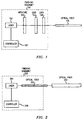
- FIG. 1 illustrates finishing assembly 100 that finishes the end of optical fiber 106 by ablating the end of optical fiber 106 to remove material containing cracks and fissures.
- the cracks and fissures resulted from the initial cutting of the end of optical fiber 106.
- Laser 101 is advantageously a Questek Model 2660, Excimer laser, that when operated advantageously at a wavelength of 248 nanometers (nm) ablates the end of optical fiber 106. Further, one skilled in the art could readily envision that wavelengths within a range of 193 to 353 nanometers could also be utilized.
- the ablation results from the absorption of the ultraviolet light from laser 101.
- the energy is only absorbed within the first micron of the end face of optical fiber 106. This absorption of energy in the first micron causes an induced instantaneous removal of material which is called ablation.
- Approximately, 1 micron of fiber is removed for each 3-5 pulses from the laser. A very precise layer of material is removed with each pulse of laser 101.
- the plastic fiber may be fabricated from polymethyl methacrylate (PMMA), a poly(butenyl vinyl ether), or a polycarbonate material.
- at least 80 microns of material is removed from the end of the plastic optical fiber to flatten it for optical transmission.
- FIG. 1 a first embodiment of the invention is illustrated.
- aperture 102 and lenses 103 and 104 are utilized to focus the light being emitted by laser 101 onto the end of optical fiber 106.
- the light is focused so that the light overlaps optical fiber 106 and is centered on the center of optical fiber 106.
- the overlapping is such that there is a 0.5 decibel difference in light intensity from the center of optical fiber 106 to the outer edge.
- optical fiber 202 is utlilized to perform mode mixing on light being emitted from laser 201.
- the resulting light being projected from optical fiber 202 onto optical fiber 203 has an even intensity across the end of optical fiber 203 so that the end of optical fiber 203 is evenly ablated.
- Optical fiber 202 is coiled into 10 coils with each coil being 10 inches in diameter.
- the end sections of optical fiber 202 that interface to laser 201 and optical fiber 203 are straight and sufficiently long to allow easy interfacing.
- optical fiber 202 has a quartz core of 300 microns.
Landscapes
- Physics & Mathematics (AREA)
- Engineering & Computer Science (AREA)
- General Physics & Mathematics (AREA)
- Optics & Photonics (AREA)
- Mechanical Engineering (AREA)
- Manufacturing & Machinery (AREA)
- Health & Medical Sciences (AREA)
- Ophthalmology & Optometry (AREA)
- Plasma & Fusion (AREA)
- Light Guides In General And Applications Therefor (AREA)
- Laser Beam Processing (AREA)
- Mechanical Coupling Of Light Guides (AREA)
- Optical Couplings Of Light Guides (AREA)
Abstract
Description
- The present invention relates to the utilization of plastic optical fiber, and, more particularly, to the finishing of an end of a plastic optical fiber for insertion into an optical connector.
- Optical plastic fibers are in general easy to work with and are economical. An ongoing problem with the utilization of plastic optical fibers has been the problem of finishing the ends of a plastic optical fiber before or after insertion into an optical connector. The prior art finishing techniques have yielded connectors with a high insertion loss. These losses are typically in the 1.5 dB to 2.0 dB range. These insertion losses are high. For example, multimode connectors made with silica fibers are typically less than 0.5 dB. Within the prior art, the finishing of ends of plastic optical fibers in the field and the manufacturing environment have utilized two or three different grits of optical polishing paper to polish the end of the optical fiber. The utilization of optical polishing paper has resulted in the high insertion losses previously mentioned. Also within the prior art, another method is used to finish the ends of plastic optical fibers. This other method is referred to as hot plate end finishing. The hot plate end finishing method typically results in losses in the 1.5 - 2.0 dB range.
- A departure in the art is achieved by an apparatus and a method for finishing an end of a plastic optical fiber by ablating the end of the plastic optical fiber by utilizing an Excimer laser. A high powered ultraviolet beam of light from the laser is absorbed by the end of the fiber and ablates the first few tens of microns of the fiber. This process removes material containing residual cracks and fissures to flatten the end of the fiber. The optical fiber is then ready to make a low loss interface with a source, a detector, or another optical fiber.
- Other and further aspects of the present invention will become apparent during the course of the following description and by reference to the accompanying drawing.
- Referring now to the drawing:
- FIG. 1 illustrates an apparatus for finishing the end of an optical fiber in accordance with a first embodiment of the invention; and
- FIG. 2 illustrates an apparatus for finishing the end of an optical fiber in accordance with a second embodiment of the invention.
-
- In accordance with a first embodiment of the invention, FIG. 1 illustrates finishing assembly 100 that finishes the end of
optical fiber 106 by ablating the end ofoptical fiber 106 to remove material containing cracks and fissures. The cracks and fissures resulted from the initial cutting of the end ofoptical fiber 106. Laser 101 is advantageously a Questek Model 2660, Excimer laser, that when operated advantageously at a wavelength of 248 nanometers (nm) ablates the end ofoptical fiber 106. Further, one skilled in the art could readily envision that wavelengths within a range of 193 to 353 nanometers could also be utilized. - The ablation results from the absorption of the ultraviolet light from
laser 101. The energy is only absorbed within the first micron of the end face ofoptical fiber 106. This absorption of energy in the first micron causes an induced instantaneous removal of material which is called ablation. Approximately, 1 micron of fiber is removed for each 3-5 pulses from the laser. A very precise layer of material is removed with each pulse oflaser 101. Advantageously, the plastic fiber may be fabricated from polymethyl methacrylate (PMMA), a poly(butenyl vinyl ether), or a polycarbonate material. Advantageously, at least 80 microns of material is removed from the end of the plastic optical fiber to flatten it for optical transmission. - In FIG. 1, a first embodiment of the invention is illustrated. In finishing assembly 100,
aperture 102 andlenses laser 101 onto the end ofoptical fiber 106. The light is focused so that the light overlapsoptical fiber 106 and is centered on the center ofoptical fiber 106. The overlapping is such that there is a 0.5 decibel difference in light intensity from the center ofoptical fiber 106 to the outer edge. - In FIG. 2, a second embodiment of the invention is illustrated. Within
finishing assembly 200,optical fiber 202 is utlilized to perform mode mixing on light being emitted fromlaser 201. The resulting light being projected fromoptical fiber 202 ontooptical fiber 203 has an even intensity across the end ofoptical fiber 203 so that the end ofoptical fiber 203 is evenly ablated.Optical fiber 202 is coiled into 10 coils with each coil being 10 inches in diameter. In addition, the end sections ofoptical fiber 202 that interface tolaser 201 andoptical fiber 203 are straight and sufficiently long to allow easy interfacing. Advantageously,optical fiber 202 has a quartz core of 300 microns.
Claims (11)
- A method for finishing an end of an optical fiber (106) for utilizing in an optical connector, comprising the steps of:generating light from an optical source (101);forming (102, 103, 104) the generated light onto the end of the optical fiber; andablating the end of the optical fiber by the formed light removing residual cracks and fissures to finish the end of the optical fiber for utilization in the optical connector.
- The method of claim 1 wherein the step of forming comprisesthe steps of focusing (103, 104) the generated light with one or more lens; andmasking (102) the focused light with an aperture.
- The method of claim 2 wherein the optical source is a laser.
- The method of claim 3 wherein the generated light has a wavelength in a range of 193 to 353 nanometers.
- The method of claim 1 wherein the step of forming comprises the step of performing mode mixing of the light.
- The method of claim 5 wherein the step of mode mixing comprises the step of transmitting the generated light through glass optical fiber.
- The method of claim 6 wherein the optical source is a laser.
- The method of claim 7 wherein the generated light has a wavelength in a range of 193 to 353 nanometers.
- An apparatus for finishing an end of an optical fiber (106) for utilizing in an optical connector, comprising:means for generating (101) light from an optical source;means for forming (102, 103, 104) the generated light onto the end of the optical fiber; and
CHARACTERIZED IN THATmeans for ablating the end of the optical fiber by the formed light removing residual cracks and fissures to finish the end of the optical fiber for utilization in the optical connector. - The apparatus of claim 9 wherein the means for forming comprises means for focusing (103, 104) the generated light with one or more lens; andmeans for masking (102) the focused light with an aperture.
- The apparatus of claim 9 wherein the means for forming comprises means for performing mode mixing of the light.
Applications Claiming Priority (2)
| Application Number | Priority Date | Filing Date | Title |
|---|---|---|---|
| US09/363,542 US6361219B1 (en) | 1999-07-29 | 1999-07-29 | End finishing of plastic optical fibers using laser ablation |
| US363542 | 1999-07-29 |
Publications (2)
| Publication Number | Publication Date |
|---|---|
| EP1075926A1 true EP1075926A1 (en) | 2001-02-14 |
| EP1075926B1 EP1075926B1 (en) | 2002-06-05 |
Family
ID=23430663
Family Applications (1)
| Application Number | Title | Priority Date | Filing Date |
|---|---|---|---|
| EP00306066A Expired - Lifetime EP1075926B1 (en) | 1999-07-29 | 2000-07-17 | End finishing of plastic optical fibers using laser ablation |
Country Status (4)
| Country | Link |
|---|---|
| US (1) | US6361219B1 (en) |
| EP (1) | EP1075926B1 (en) |
| JP (1) | JP2001074942A (en) |
| DE (1) | DE60000195T2 (en) |
Cited By (1)
| Publication number | Priority date | Publication date | Assignee | Title |
|---|---|---|---|---|
| WO2003085432A3 (en) * | 2002-04-04 | 2003-11-27 | Photon X Inc | Endface preparation method for polymer optical waveguides on polymer substrates |
Families Citing this family (29)
| Publication number | Priority date | Publication date | Assignee | Title |
|---|---|---|---|---|
| US6500353B1 (en) * | 1999-06-25 | 2002-12-31 | Fitel Usa Corp. | Disposable device for end finishing of plastic optical fiber |
| US6822190B2 (en) | 2002-12-12 | 2004-11-23 | 3M Innovative Properties Company | Optical fiber or waveguide lens |
| US7993808B2 (en) * | 2005-09-30 | 2011-08-09 | Taiwan Semiconductor Manufacturing Company, Ltd. | TARC material for immersion watermark reduction |
| WO2007136754A2 (en) | 2006-05-19 | 2007-11-29 | Boston Scientific Limited | Control mechanism for steerable medical device |
| US20090041412A1 (en) * | 2007-08-07 | 2009-02-12 | Jeffrey Dean Danley | Laser erosion processes for fiber optic ferrules |
| US20090299352A1 (en) * | 2007-12-21 | 2009-12-03 | Boston Scientific Scimed, Inc. | Steerable laser-energy delivery device |
| DE102008002534A1 (en) | 2008-06-19 | 2009-12-31 | Laser-Laboratorium Göttingen e.V. | Optical functional surfaces |
| US8740474B2 (en) | 2011-04-12 | 2014-06-03 | Adc Telecommunications, Inc. | Methods for processing a multi-fiber ferrule |
| GB201116675D0 (en) * | 2011-09-28 | 2011-11-09 | Bae Systems Plc | Plastic optical fibres |
| US9205609B1 (en) | 2011-12-21 | 2015-12-08 | Corning Cable Systems Llc | Laser cutting and polishing methods for optical fibers and fibers resulting |
| US8764314B2 (en) | 2012-06-15 | 2014-07-01 | Corning Cable Systems Llc | Optical fiber and composite inorganic ferrule assemblies and methods |
| US8985866B2 (en) | 2012-06-20 | 2015-03-24 | Corning Cable Systems Llc | Simultaneous thermal forming of ferrule and optical fiber in a ferrule assembly to thermally form an optical surface in the ferrule assembly, and related fiber optic components, fiber connectors, assemblies, and methods |
| US9205610B1 (en) * | 2012-09-17 | 2015-12-08 | Corning Cable Systems Llc | Head-on laser shaping of optical surfaces of optical fibers, and related assemblies and methods |
| US8696215B1 (en) | 2012-10-15 | 2014-04-15 | Corning Cable Systems Llc | Adhesive compositions including partially cross-linked resins and coupling agents and methods for use thereof |
| US9039295B2 (en) | 2012-10-15 | 2015-05-26 | Corning Cable Systems Llc | Adhesive compositions including partially cross-linked resins and thermoset resins and methods for use thereof |
| US9568686B2 (en) | 2012-10-15 | 2017-02-14 | Corning Optical Communications LLC | Optical connector and ferrule adhesion system including adhesive composition, and related methods |
| US8840318B2 (en) | 2012-10-15 | 2014-09-23 | Corning Cable Systems Llc | Ferrule with stress-isolation feature |
| US9880362B2 (en) | 2012-10-22 | 2018-01-30 | Corning Optical Communications LLC | Methods of securing one or more optical fibers to a ferrule |
| US8753021B1 (en) | 2013-02-12 | 2014-06-17 | Corning Cable Systems Llc | Adhesives for securing optical fibers to ferrules of optical connectors and methods for use thereof |
| US9089931B1 (en) | 2013-03-11 | 2015-07-28 | Corning Cable Systems Llc | Systems and methods for laser cleaving optical fibers |
| US9052469B2 (en) | 2013-04-26 | 2015-06-09 | Corning Cable Systems Llc | Preterminated fiber optic connector sub-assemblies, and related fiber optic connectors, cable assemblies, and methods |
| US9085047B2 (en) | 2013-05-10 | 2015-07-21 | Corning Optical Communications LLC | Coating removal systems for optical fibers |
| US8755654B1 (en) | 2013-05-10 | 2014-06-17 | Corning Cable Systems Llc | Coating removal systems for optical fibers |
| US8702322B1 (en) | 2013-06-03 | 2014-04-22 | Corning Cable Systems Llc | Optical connector with adhesive material |
| US9588303B2 (en) | 2013-06-03 | 2017-03-07 | Corning Optical Communications LLC | Optical connector with adhesive material |
| US9791637B2 (en) | 2014-04-21 | 2017-10-17 | Corning Optical Communications LLC | Methods of terminating one or more optical fibers |
| CN107076938B (en) | 2014-08-20 | 2019-10-15 | Adc电信公司 | Method for laser processing of multi-fiber ferrules |
| EP3096163A1 (en) | 2015-05-22 | 2016-11-23 | Corning Optical Communications LLC | Quantum cascade laser devices and methods for optical-fiber processing for connector applications |
| EP3377929A4 (en) | 2015-11-18 | 2019-08-07 | Commscope Technologies LLC | Methods for processing ferrules and/or optical fibers |
Citations (7)
| Publication number | Priority date | Publication date | Assignee | Title |
|---|---|---|---|---|
| JPS59189301A (en) * | 1983-04-12 | 1984-10-26 | Sumitomo Electric Ind Ltd | How to polish plastic fiber |
| EP0393601A2 (en) * | 1989-04-18 | 1990-10-24 | The Whitaker Corporation | Holder for optical fiber end-processing device |
| US5101090A (en) * | 1990-11-19 | 1992-03-31 | At&T Bell Laboratories | Methods and apparatus for making optical fiber couplers |
| US5130512A (en) * | 1989-12-21 | 1992-07-14 | Coyle Jr Richard J | Fabrication of optical components utilizing a laser |
| US5395362A (en) * | 1992-01-14 | 1995-03-07 | Summit Technology | Methods and apparatus for distributing laser radiation |
| US5421928A (en) * | 1994-07-01 | 1995-06-06 | Siecor Corporation | Laser removal of excess optical fiber prior to connector polishing |
| WO1997048995A1 (en) * | 1996-06-19 | 1997-12-24 | Visionex, Inc. | Fiber optic interface for optical probes with enhanced photonic efficiency, light manipulation, and stray light rejection |
Family Cites Families (7)
| Publication number | Priority date | Publication date | Assignee | Title |
|---|---|---|---|---|
| US4544231A (en) * | 1983-06-29 | 1985-10-01 | The United States Of America As Represented By The Secretary Of The Department Of Health & Human Services | Method of joining plastic optical fibers and connections obtained |
| JPS623208A (en) * | 1985-06-28 | 1987-01-09 | Sumitomo Electric Ind Ltd | Connecting method for optical fibers |
| US4770653A (en) * | 1987-06-25 | 1988-09-13 | Medilase, Inc. | Laser angioplasty |
| US5026411A (en) * | 1989-12-21 | 1991-06-25 | At&T Bell Laboratories | Fabrication of optical couplers |
| US5143531A (en) * | 1991-04-10 | 1992-09-01 | The United States Of America As Represented By The United States Department Of Energy | Hermetic fiber optic-to-metal connection technique |
| US5287426A (en) * | 1993-02-22 | 1994-02-15 | At&T Bell Laboratories | Methods for making optical fiber connectors |
| JPH07234341A (en) * | 1994-02-23 | 1995-09-05 | Nec Corp | Coupling structure of semiconductor laser and optical fiber |
-
1999
- 1999-07-29 US US09/363,542 patent/US6361219B1/en not_active Expired - Lifetime
-
2000
- 2000-07-17 EP EP00306066A patent/EP1075926B1/en not_active Expired - Lifetime
- 2000-07-17 DE DE60000195T patent/DE60000195T2/en not_active Expired - Lifetime
- 2000-07-28 JP JP2000228342A patent/JP2001074942A/en active Pending
Patent Citations (7)
| Publication number | Priority date | Publication date | Assignee | Title |
|---|---|---|---|---|
| JPS59189301A (en) * | 1983-04-12 | 1984-10-26 | Sumitomo Electric Ind Ltd | How to polish plastic fiber |
| EP0393601A2 (en) * | 1989-04-18 | 1990-10-24 | The Whitaker Corporation | Holder for optical fiber end-processing device |
| US5130512A (en) * | 1989-12-21 | 1992-07-14 | Coyle Jr Richard J | Fabrication of optical components utilizing a laser |
| US5101090A (en) * | 1990-11-19 | 1992-03-31 | At&T Bell Laboratories | Methods and apparatus for making optical fiber couplers |
| US5395362A (en) * | 1992-01-14 | 1995-03-07 | Summit Technology | Methods and apparatus for distributing laser radiation |
| US5421928A (en) * | 1994-07-01 | 1995-06-06 | Siecor Corporation | Laser removal of excess optical fiber prior to connector polishing |
| WO1997048995A1 (en) * | 1996-06-19 | 1997-12-24 | Visionex, Inc. | Fiber optic interface for optical probes with enhanced photonic efficiency, light manipulation, and stray light rejection |
Non-Patent Citations (1)
| Title |
|---|
| PATENT ABSTRACTS OF JAPAN vol. 009, no. 050 (P - 339) 5 March 1985 (1985-03-05) * |
Cited By (1)
| Publication number | Priority date | Publication date | Assignee | Title |
|---|---|---|---|---|
| WO2003085432A3 (en) * | 2002-04-04 | 2003-11-27 | Photon X Inc | Endface preparation method for polymer optical waveguides on polymer substrates |
Also Published As
| Publication number | Publication date |
|---|---|
| US6361219B1 (en) | 2002-03-26 |
| EP1075926B1 (en) | 2002-06-05 |
| DE60000195T2 (en) | 2002-12-12 |
| JP2001074942A (en) | 2001-03-23 |
| DE60000195D1 (en) | 2002-07-11 |
Similar Documents
| Publication | Publication Date | Title |
|---|---|---|
| US6361219B1 (en) | End finishing of plastic optical fibers using laser ablation | |
| US6822190B2 (en) | Optical fiber or waveguide lens | |
| US5256851A (en) | Microlenses for coupling optical fibers to elliptical light beams | |
| US5966485A (en) | Method of producing core protrusion relative to cladding in an optical fiber of a fiber optic connector | |
| US7082250B2 (en) | Laser cleaving method and apparatus for optical fiber cables | |
| US9915791B2 (en) | Method of laser polishing a connectorized optical fiber and a connectorized optical fiber formed in accordance therewith | |
| CN108351476B (en) | Method for processing ferrules and/or optical fibers | |
| JP2005538392A5 (en) | ||
| EP0142026A2 (en) | Method for constructing microlens ends for optical fibres, particularly for biomedical and/or surgical use, and device for implementing the method | |
| EP0980011A1 (en) | Optical fibre with tapered end and method of manufacture | |
| US5135555A (en) | Apparatus for fabrication of optical couplers | |
| CN111302616B (en) | A kind of laser direct writing preparation method of chalcogenide glass fiber | |
| JP2004518157A (en) | Laser cutting method and apparatus for optical fiber or waveguide | |
| CN1672073A (en) | Microstructure of Femtosecond Optical Pulse Optical Waveguide Device | |
| CN109633822A (en) | A kind of optical fiber bessel beam generator and preparation method thereof | |
| US20090202201A1 (en) | Mode selective fiber stub, a transmitter optical subassembly that incorporates the stub and methods for making the mode selective fiber stub | |
| EP4170396A1 (en) | Laser polishing of an optical fiber with control of end face shape of optical fiber | |
| US4989936A (en) | Fabrication of optical components utilizing a laser | |
| US5130512A (en) | Fabrication of optical components utilizing a laser | |
| US5026411A (en) | Fabrication of optical couplers | |
| JP2000321470A (en) | Optical fiber and laser processing machine | |
| JPS5817925B2 (en) | Multi-core optical fiber cutting machine | |
| WO2016073278A1 (en) | Methods for stripping an optical fiber coating using blue or blue-violet radiation | |
| Coric et al. | Contrasts in writing photonic structures with ultrafast and ultraviolet lasers | |
| JP2004325221A (en) | Optical fiber probe and method for manufacturing the same |
Legal Events
| Date | Code | Title | Description |
|---|---|---|---|
| PUAI | Public reference made under article 153(3) epc to a published international application that has entered the european phase |
Free format text: ORIGINAL CODE: 0009012 |
|
| 17P | Request for examination filed |
Effective date: 20000727 |
|
| AK | Designated contracting states |
Kind code of ref document: A1 Designated state(s): DE GB |
|
| AX | Request for extension of the european patent |
Free format text: AL;LT;LV;MK;RO;SI |
|
| 17Q | First examination report despatched |
Effective date: 20010216 |
|
| GRAG | Despatch of communication of intention to grant |
Free format text: ORIGINAL CODE: EPIDOS AGRA |
|
| AKX | Designation fees paid |
Free format text: DE GB |
|
| GRAG | Despatch of communication of intention to grant |
Free format text: ORIGINAL CODE: EPIDOS AGRA |
|
| GRAH | Despatch of communication of intention to grant a patent |
Free format text: ORIGINAL CODE: EPIDOS IGRA |
|
| GRAH | Despatch of communication of intention to grant a patent |
Free format text: ORIGINAL CODE: EPIDOS IGRA |
|
| GRAA | (expected) grant |
Free format text: ORIGINAL CODE: 0009210 |
|
| AK | Designated contracting states |
Kind code of ref document: B1 Designated state(s): DE GB |
|
| REG | Reference to a national code |
Ref country code: GB Ref legal event code: FG4D |
|
| REF | Corresponds to: |
Ref document number: 60000195 Country of ref document: DE Date of ref document: 20020711 |
|
| PLBE | No opposition filed within time limit |
Free format text: ORIGINAL CODE: 0009261 |
|
| STAA | Information on the status of an ep patent application or granted ep patent |
Free format text: STATUS: NO OPPOSITION FILED WITHIN TIME LIMIT |
|
| 26N | No opposition filed |
Effective date: 20030306 |
|
| REG | Reference to a national code |
Ref country code: GB Ref legal event code: 732E Free format text: REGISTERED BETWEEN 20131107 AND 20131113 |
|
| PGFP | Annual fee paid to national office [announced via postgrant information from national office to epo] |
Ref country code: DE Payment date: 20170724 Year of fee payment: 18 Ref country code: GB Payment date: 20170719 Year of fee payment: 18 |
|
| REG | Reference to a national code |
Ref country code: DE Ref legal event code: R119 Ref document number: 60000195 Country of ref document: DE |
|
| REG | Reference to a national code |
Ref country code: GB Ref legal event code: 732E Free format text: REGISTERED BETWEEN 20190131 AND 20190206 |
|
| GBPC | Gb: european patent ceased through non-payment of renewal fee |
Effective date: 20180717 |
|
| PG25 | Lapsed in a contracting state [announced via postgrant information from national office to epo] |
Ref country code: DE Free format text: LAPSE BECAUSE OF NON-PAYMENT OF DUE FEES Effective date: 20190201 Ref country code: GB Free format text: LAPSE BECAUSE OF NON-PAYMENT OF DUE FEES Effective date: 20180717 |