EP1075914A2 - Biscuit jointer - Google Patents
Biscuit jointer Download PDFInfo
- Publication number
- EP1075914A2 EP1075914A2 EP00306827A EP00306827A EP1075914A2 EP 1075914 A2 EP1075914 A2 EP 1075914A2 EP 00306827 A EP00306827 A EP 00306827A EP 00306827 A EP00306827 A EP 00306827A EP 1075914 A2 EP1075914 A2 EP 1075914A2
- Authority
- EP
- European Patent Office
- Prior art keywords
- joiner
- housing
- user
- handle portion
- stick handle
- Prior art date
- Legal status (The legal status is an assumption and is not a legal conclusion. Google has not performed a legal analysis and makes no representation as to the accuracy of the status listed.)
- Granted
Links
Images


Classifications
-
- B—PERFORMING OPERATIONS; TRANSPORTING
- B27—WORKING OR PRESERVING WOOD OR SIMILAR MATERIAL; NAILING OR STAPLING MACHINES IN GENERAL
- B27F—DOVETAILED WORK; TENONS; SLOTTING MACHINES FOR WOOD OR SIMILAR MATERIAL; NAILING OR STAPLING MACHINES
- B27F5/00—Slotted or mortised work
- B27F5/02—Slotting or mortising machines tools therefor
- B27F5/023—Portable plate joiners
Definitions
- This invention relates to plate or biscuit joiners, and more particularly to a cordless biscuit joiner having an ergonomically formed handle portion to enable a user to more comfortably handle the tool more closely to the center of gravity of the tool, and to exert a linear force substantially along the longitudinal axis of the motor of the tool to thus further improve the operator's control over the tool and to further reduce operator fatigue when using the tool.
- Biscuit joiners are used in a variety of wood-working applications to cut slot-like recesses into the surfaces of wood members that are to be joined in facing relationship to one another.
- glue is applied to one or both of the recesses and a wood disc-like member termed a "biscuit" is urged into one of the recesses such that it projects partially therefrom.
- the other wood member is placed adjacent the protruding edge of the biscuit and the protruding edge is then urged into the recess of the facing wood member as the two wood members are forced against each other.
- Traditional biscuit joiners typically incorporate some form of shoe assembly which houses the cutting blade.
- a fence assembly allows the wood member to be positioned thereagainst at a desired angle relative to the shoe assembly.
- a stick-type handle/housing is secured to the shoe assembly and encloses the electric motor of the tool.
- the rear portion of the handle/housing forms a generally cylindrical stick-type handle which the user grasps when using the joiner. The user exerts a force toward the wood member being cut which causes the cutting blade to be urged outwardly of the shoe assembly to thereby cut the slot-like opening in the wood member.
- One such type of joiner is presently offered by the assignee of the present application in an AC powered version, which has been very well received in the industry.
- the battery pack should not upset the overall balance of the tool or require additional effort to be expended by the user when using the tool just to compensate for the additional weight of the battery.
- Offsetting the stick handle portion slightly from the rest of the housing also enables the user to grasp the stick handle portion more forwardly thereon (i.e., to "choke up” on the stick handle portion) with his/her hand, thus enabling the user's hand to be placed closer to the overall center of gravity of the tool.
- These ergonomic improvements can help to significantly improve the comfort, balance and overall "feel" of the joiner, as well as to reduce the fatigue experienced by an individual when using the joiner over a prolonged period of time.
- a biscuit joiner having a handle assembly which serves to place the hand of the user that is used to engage the ON/OFF trigger of the tool in an orientation which is even more comfortable and ergonomically efficient for the user. More specifically, it is an object to form the stick handle portion of the tool such that the user is able to exert a force, when using the tool, that is directed substantially along the longitudinal axis of the main body of the joiner. In this manner the force transmitted by the user's hand which is gripping the stick handle portion can be transmitted even more efficiently and comfortably when making plunge cuts with the joiner.
- the present invention is directed to a biscuit joiner having an ergonomically designed handle assembly.
- the handle assembly comprises a stick handle portion and a loop portion.
- the stick handle portion is laterally offset from a motor housing portion of the joiner which encases an electric motor.
- the lateral offset of the stick handle portion even further improves the transmission of force by the hand that is grasping the stick handle portion during use of the joiner.
- the lateral offset of the stick handle portion also enables the user to grip more forwardly on the stick handle portion such that the hand that is grasping the stick handle portion is able to be placed closer to the overall center of gravity of the joiner.
- the joiner comprises a cordless joiner having a removable, rechargeable battery pack.
- the joiner also includes a loop handle portion formed underneath the stick handle portion.
- the loop handle portion and the battery pack can both help to support the tool on a flat work surface when the tool is not in use.
- the loop handle portion can also enable the user to grasp and support the joiner with a wider variety of hand positions during use of the tool.
- the various preferred embodiments provide a biscuit joiner which is more ergonomically efficient and even more comfortable to operate than previously designed joiners, even when a rechargeable battery pack is attached to the rear area of the joiner.
- the stick handle and loop handle portions further enable a wider variety of hand positions to be accommodated comfortably when using the joiner while providing the tool with a well balanced "feel". These features help to reduce operator fatigue when using the joiner over a prolonged period of time.
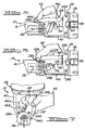
- the biscuit joiner 10 is shown in accordance with a preferred embodiment of the present invention.
- the biscuit joiner generally comprises a shoe assembly 12 and a fence assembly 14 which are each attached to a housing 16.
- the shoe assembly 12 has a recess 18 within which is disposed a cutting blade 20.
- An opening 22 at a front portion 24 of the shoe assembly 12 enables the cutting blade 20 to be urged outwardly of the shoe assembly 12 during use of the joiner 10.
- the housing 16 includes a forward portion 26, a handle portion 28 and a rear portion 30.
- the forward portion 26 houses an electric motor 32 having an output shaft coupled to a gear reduction assembly 34.
- the gear reduction assembly 34 has its output coupled to the cutting blade 20.
- the longitudinal axis of rotation of the output shaft of the electric motor 32, which coincides with the approximate coaxial center of the forward portion 26, is indicated by arrow 36.
- a forward handle 38 is secured to the forward portion 26 of the housing 16. Further details of the construction of fence assembly 14 and the shoe assembly 12 can be found in U.S. Patent No. 4,913,204, assigned to the assignee of the present application, and the disclosure of which is hereby incorporated by reference.
- the forward portion 26 of the housing 16 is formed as a generally circular, single-piece section.
- the handle portion 28 extends from the forward portion 26 and is formed in a two-piece, clamshell-type configuration.
- the two housing halves comprising the handle portion 28 are held together by threaded screws 28b that engage in four bosses 28a (only two of which are visible in Figure 1).
- the housing 16 is preferably manufactured from suitable high strength plastics through conventional injection molding techniques.
- the handle portion 28 includes a main or stick handle portion 40 which is slightly oblong when assembled and viewed in cross-section.
- a foam-like material 40a which serves as padding for the user's hand can also be secured to an upper portion of the stick handle portion 40 by a suitable adhesive, as best seen in Figures 2 and 3.
- the stick handle portion 40 also includes an arcuate portion 40b providing a comfortable position for the user's thumb. As will be explained more fully in connection with Figure 5, the arcuate portion 40b enables a user to grip the stick handle portion 40 more forwardly thereon so that the user's hand is closer to the overall center of gravity of the joiner 10.
- a loop portion 42 also extends from the forward portion 26 of the housing 16 to the rear portion 30.
- Each of the stick handle portion 40 and loop portion 42 are formed so as to be offset laterally from the central longitudinal axis of the forward portion 26, which coincides with the longitudinal axis of the forward portion 26 of the housing 16 and also with the longitudinal axis of rotation of the motor 32, indicated by arrow 36. This lateral offset enables a force to be transmitted by the user's hand even more directly along the longitudinal axis of the motor 32 and the forward portion 26 of the housing 16, and therefore enhances the ergonomic efficiency and comfort to the user when using the joiner 10.
- the stick handle portion 40 of the handle portion 28 further includes an electrical ON/OFF switch 44 having a trigger portion 46 used for electrically closing the switch.
- the trigger portion 46 is disposed for sliding movement through an opening 48 in the stick handle portion 40.
- the switch 44 is a normally open, spring biased switch which is electrically closed when the user actuates (i.e., squeezes) the trigger portion 46.
- the switch 44 is electrically coupled between the electric motor 32 and a terminal block 50 via suitable electrical conductors (not shown).
- the terminal block 50 is supported within a pair of channels 52 protruding from an interior surface 54 of the stick handle portion 40.
- the terminal block 50 is used to electrically couple DC power from the electrical contacts of a removable battery pack 56 to the motor 32 when the battery pack 56 is attached to the housing 16.
- the battery pack 56 is held removably to the housing 16 by a pair of identical, resilient latch arms 58 on opposite sides of the rear portion 30 of the housing 16 (with only one latch arm 58 being visible in Figures 1, 2 and 4).
- the latch arms 58 extend through openings 60 formed in a casing 62 of the battery pack 56 and engage with the casing 62 to hold it securely to the rear portion 30 of the housing 16.
- the battery pack 56 is of the rechargeable type and therefore comprises one or more lead acid battery cells or nickel cadmium cells. It will be appreciated, however, that the joiner 10 could just as easily be modified to be powered from an AC power source. Also, it is anticipated that an AC/DC converter could also be used to provide power to the joiner 10 in place of the battery pack 56. An AC/DC converter would be helpful in the event the battery pack 56 becomes discharged to the point where a task cannot be completed without first recharging the battery pack 56. In this event, the AC/DC converter could be attached to the joiner 10 in place of the battery pack 56 and then a power cord of the converter plugged into an available AC power outlet. This would provide power to enable the joiner 10 to be used to complete the woodworking task at hand.
- the rear portion 30 of the housing 16 is also enlarged so as to be able to better mate with the battery pack 56.
- enlarged it is meant that the perimeter of the rear portion 30 extends laterally beyond the outer surface of the front portion 26 of the housing 16. This feature also enables the rear portion 30 along with battery 56 to help support the joiner 10 when the joiner is rested on a planar work surface when not in use.
- the joiner 10 It is a principal advantage of the joiner 10 that the stick handle 40 of the forward portion 26 is laterally offset from the longitudinal axis 36 about which the armature of the motor 32 rotates. This allows one grip to be used where the forefinger 64 of a user's hand 66, as well as the remaining fingers being used to grasp the stick handle portion 40, are able to exert a force even more directly along the longitudinal axis 36 of the forward portion 26 of the housing 16. This direct application of force along the longitudinal axis 36 provides the user with an even more positive and balanced "feel" when using the joiner 10. It also substantially eliminates the small moment arm that could be created if the user is exerting a force which is directed along a line laterally offset from the motor rotational axis while making a plunge cut with the joiner 10.
- the laterally offset configuration of the stick handle portion 40 significantly adds to the comfort and ease in using the joiner 10. This feature also serves to help reduce hand and arm fatigue when the joiner 10 is used repeatedly over a short period of time.
- FIG. 5 another grip orientation is illustrated.
- the joiner 10 is illustrated with the user grasping the stick handle portion 40 at a more forward portion thereof.
- the hand 66 of the user that is grasping the stick handle portion 40 is very close to the center of gravity of the joiner 10. This provides the user with an excellent sense of control and a balanced "feel" for the joiner 10 when handling and making plunge cuts with the joiner 10.
- Figure 6 illustrates the stick handle portion 40 being grasped at a forwardmost portion thereof. With this grip the last two fingers of the user's hand 66 can be used to engage and hold the trigger portion 46.
- Figure 7 illustrates the joiner 10 being held by the user's hand 66 with a reverse grip on the stick handle portion 40. With this grip, the trigger portion 46 can be engaged by the second and third fingers 66a and 66b, respectively, while the joiner 10 is held in a vertical orientation.
- the handle portion 28 thus enables a variety of hand positions to be used, which makes the joiner 10 even more comfortable to operate than existing stick handle type joiners when the joiner 10 is used to make plunge cuts in workpieces that are positioned in a variety of angular positions.
- the joiner 10 can thus be held easily and comfortably in a variety of positions while providing a well balanced and positive feel.
- the offset orientation of the stick handle portion 40 permits the user to apply force directly along the housing 16 of the joiner 10, thus providing a positive, balanced feel to the joiner 10.
Landscapes
- Engineering & Computer Science (AREA)
- Life Sciences & Earth Sciences (AREA)
- Wood Science & Technology (AREA)
- Mechanical Engineering (AREA)
- Forests & Forestry (AREA)
- Harvester Elements (AREA)
- Portable Power Tools In General (AREA)
- Gripping On Spindles (AREA)
- Holders For Apparel And Elements Relating To Apparel (AREA)
- Toys (AREA)
- Scissors And Nippers (AREA)
- Mechanical Pencils And Projecting And Retracting Systems Therefor, And Multi-System Writing Instruments (AREA)
- Footwear And Its Accessory, Manufacturing Method And Apparatuses (AREA)
- Sawing (AREA)
- Confectionery (AREA)
- Fishing Rods (AREA)
- Adornments (AREA)
Abstract
Description
Claims (26)
- A joiner comprising:a housing;an electric motor disposed within said housing;a cutting blade operably associated with said motor so as to by driven by said motor;a shoe assembly for housing said cutting blade; andsaid housing having a forward portion for housing said motor and an elongated handle portion graspable by a user, which is offset laterally from a longitudinal axis of said forward portion of said housing, to thereby place the fingers of a hand of the user approximately behind and generally in-line with the forward portion of the housing when operating said joiner.
- The joiner of claim 1, wherein said elongated handle portion comprises a stick handle portion, and wherein said lateral offset of said stick handle portion is sufficient to place said fingers along a longitudinal axis extending through a coaxial center of said forward portion of said housing and through an axis of rotation of said motor.
- The joiner of claim 1, wherein said elongated handle portion comprises a stick handle portion and a loop portion both extending from said forward portion of said housing.
- The joiner of claim 3, wherein said stick handle portion includes a trigger switch operably associated with said electric motor and disposed so as to be engageable with a finger of the user's hand when operating said joiner.
- The joiner of claim 1, further comprising a removable battery pack coupled to said housing for powering said electric motor.
- The joiner of claim 1, wherein said forward portion of said housing forms a tubular single piece portion of said housing for housing said electric motor.
- The joiner of claim 1, wherein said elongated handle portion comprises a two-piece clamshell construction.
- The joiner of claim 3, wherein said loop portion extends generally parallel with said main portion of said handle.
- The joiner of claim 1, wherein said housing includes:
a rear portion separated from said forward portion by said elongated handle portion, said rear portion extending laterally beyond said forward portion to assist in supporting said housing on a work surface when said joiner is not in use. - A joiner comprising:a housing having a forward portion and a handle portion;an electric motor disposed within said forward portion of said housing;a battery pack for powering said electric motor;a cutting blade driven by said electric motor;a shoe assembly secured to said forward portion of said housing for housing said cutting blade; andsaid handle portion of said housing having a stick handle portion which is graspable by a user and offset laterally from said forward portion, to thereby place the fingers of the user approximately along a longitudinal axis of said forward portion of said housing when said user is grasping said handle portion while operating said joiner, to thereby enable said user to apply a force with said hand that is substantially along said longitudinal axis of said forward portion of said housing.
- The joiner of claim 10, wherein said housing further comprises a loop portion offset laterally from said forward portion of said housing and extending generally parallel to said stick handle portion.
- The joiner of claim 11, wherein said housing includes a rear portion bridging said loop and stick handle portions, said rear portion further supporting said battery pack thereon.
- The joiner of claim 12, wherein said battery pack is releasably secureable to said rear portion of said housing.
- The joiner of claim 10, wherein said stick handle portion of said housing includes a trigger switch engageable by a finger of said user when grasping said stick handle portion.
- The joiner of claim 10, further including a fence assembly and a forward handle secured to said fence assembly, said forward handle being graspable by one hand of the user when operating said joiner.
- A joiner comprising:a housing having an elongated forward portion, a stick handle portion and a loop handle portion each extending from said forward portion, at least said stick handle portion being laterally offset from said forward portion, and said stick handle and said loop handle portions being bridged by a rear portion of said housing to form a loop through which the fingers of a user may extend;an electric motor disposed within said forward portion of said housing; anda cutting implement driven by said electric motor.
- The joiner of claim 16, further comprising:
a battery pack releasably secureable to said rear portion of said housing for powering said electric motor. - The joiner of claim 16, wherein said stick handle portion includes an ON/OFF trigger for actuating said electric motor.
- The joiner of claim 16, wherein said stick handle portion is offset laterally a degree sufficient to place the fingers of a user substantially along a longitudinal axis of said forward portion of said housing when said user grips said stick handle portion with one hand.
- The joiner of claim 16, wherein each of said stick handle portion and said loop handle portion are laterally offset from said forward portion of said housing.
- A cordless plate joiner comprising:a main housing having opposed ends;an electric motor within the main housing;a cutting blade connected to and driveable by the motor;a shoe assembly connected to one end of the main housing;a handle formed at the second end of the main housing;the handle having a stick handle portion and a loop portion; anda battery pack bridging the loop and main portion of the handle.
- The cordless joiner of claim 21, wherein the housing further comprises a rear portion bridging said stick handle and said loop portions, said battery pack being removably secured to said rear portion.
- The cordless joiner of claim 21, wherein said stick handle portion is laterally offset from, and extends generally parallel to, said main housing such that when said stick handle portion is gripped by a hand of a user, the fingers of said hand are positioned generally in line with a longitudinal axis extending through a general coaxial center of said main housing.
- The cordless joiner of claim 21, wherein said stick handle portion includes a forward, rounded portion.
- The joiner of claim 21, wherein said stick handle portion includes a trigger switch engageable by a finger of said user when said user is grasping said stick handle portion.
- The joiner of claim 21, further comprising a forward handle secured at or adjacent said first end of said main housing and being graspable with said user's other hand when operating said joiner.
Priority Applications (2)
| Application Number | Priority Date | Filing Date | Title |
|---|---|---|---|
| EP06120953A EP1731278B1 (en) | 1999-08-11 | 2000-08-10 | Biscuit Joiner |
| EP07119040A EP1875995A1 (en) | 1999-08-11 | 2000-08-10 | Biscuit joiner |
Applications Claiming Priority (2)
| Application Number | Priority Date | Filing Date | Title |
|---|---|---|---|
| US09/372,311 US6260591B1 (en) | 1999-08-11 | 1999-08-11 | Biscuit joiner |
| US372311 | 1999-08-11 |
Related Child Applications (1)
| Application Number | Title | Priority Date | Filing Date |
|---|---|---|---|
| EP06120953A Division EP1731278B1 (en) | 1999-08-11 | 2000-08-10 | Biscuit Joiner |
Publications (3)
| Publication Number | Publication Date |
|---|---|
| EP1075914A2 true EP1075914A2 (en) | 2001-02-14 |
| EP1075914A3 EP1075914A3 (en) | 2005-07-13 |
| EP1075914B1 EP1075914B1 (en) | 2007-10-24 |
Family
ID=23467621
Family Applications (3)
| Application Number | Title | Priority Date | Filing Date |
|---|---|---|---|
| EP00306827A Expired - Lifetime EP1075914B1 (en) | 1999-08-11 | 2000-08-10 | Biscuit jointer |
| EP07119040A Withdrawn EP1875995A1 (en) | 1999-08-11 | 2000-08-10 | Biscuit joiner |
| EP06120953A Expired - Lifetime EP1731278B1 (en) | 1999-08-11 | 2000-08-10 | Biscuit Joiner |
Family Applications After (2)
| Application Number | Title | Priority Date | Filing Date |
|---|---|---|---|
| EP07119040A Withdrawn EP1875995A1 (en) | 1999-08-11 | 2000-08-10 | Biscuit joiner |
| EP06120953A Expired - Lifetime EP1731278B1 (en) | 1999-08-11 | 2000-08-10 | Biscuit Joiner |
Country Status (9)
| Country | Link |
|---|---|
| US (1) | US6260591B1 (en) |
| EP (3) | EP1075914B1 (en) |
| JP (1) | JP2001079784A (en) |
| AT (1) | ATE376486T1 (en) |
| AU (1) | AU770785B2 (en) |
| CA (1) | CA2315320A1 (en) |
| DE (2) | DE60036838T2 (en) |
| DK (1) | DK1075914T3 (en) |
| ES (1) | ES2292408T3 (en) |
Cited By (1)
| Publication number | Priority date | Publication date | Assignee | Title |
|---|---|---|---|---|
| EP2572835A1 (en) * | 2011-09-22 | 2013-03-27 | Makita Corporation | Rechargeable plate joiner |
Families Citing this family (14)
| Publication number | Priority date | Publication date | Assignee | Title |
|---|---|---|---|---|
| US6368033B2 (en) * | 2000-06-26 | 2002-04-09 | Steven Howell Souders | Right-angle plunge router |
| US6558090B2 (en) * | 2001-06-15 | 2003-05-06 | Porter-Cable/Delta | Cordless router |
| US6449852B1 (en) * | 2001-09-17 | 2002-09-17 | David Simantel | Casing and door jamb trimmer |
| US6846138B1 (en) * | 2002-07-23 | 2005-01-25 | Porter-Cable Corporation | Offset base router |
| DE102005027195A1 (en) * | 2005-06-06 | 2006-12-14 | C. & E. Fein Gmbh | Method and device for producing slots in workpieces |
| US20070074407A1 (en) * | 2005-09-30 | 2007-04-05 | Serdynski David P | Tool and method of using same |
| US7310879B1 (en) | 2006-07-27 | 2007-12-25 | Robert Bosch Gmbh | Cutting attachment having an adjustable foot for rotary hand tools |
| US7596872B2 (en) * | 2006-07-27 | 2009-10-06 | Robert Bosch Gmbh | Cutting attachment with a removable cover for rotary hand tools |
| ES2317821T3 (en) * | 2007-05-08 | 2015-10-15 | Franz Baur | Means and method of joining to establish a union of a first component to a second component |
| JP5431744B2 (en) * | 2009-02-10 | 2014-03-05 | 株式会社やまびこ | Top handle type portable power working machine |
| CN102241011A (en) * | 2011-06-30 | 2011-11-16 | 苏州百泰柯机械有限公司 | Portable electric pincers |
| CN104128973B (en) * | 2014-07-16 | 2016-05-25 | 北京工业大学 | The vertical sleeping turning device of a kind of main shaft |
| US11084006B2 (en) | 2017-03-23 | 2021-08-10 | Milwaukee Electric Tool Corporation | Mud mixer |
| DE102018009173A1 (en) * | 2018-11-19 | 2020-05-20 | AuMeta GmbH | Electric hand tool, in particular for translationally moving a work tool |
Family Cites Families (40)
| Publication number | Priority date | Publication date | Assignee | Title |
|---|---|---|---|---|
| US3757194A (en) | 1972-07-03 | 1973-09-04 | Black & Decker Mfg Co | Cordless power tool having removable battery pack |
| JPS4930996A (en) | 1972-07-20 | 1974-03-19 | ||
| US3973179A (en) | 1974-08-23 | 1976-08-03 | The Black And Decker Manufacturing Company | Modular cordless tools |
| US4461330A (en) | 1982-08-06 | 1984-07-24 | Judkins Donald J | Portable woodworking power tool |
| JPS60240693A (en) | 1984-05-07 | 1985-11-29 | 愛知電機株式会社 | Electric can opener |
| GB2180782B (en) | 1985-09-23 | 1989-12-13 | Black & Decker Inc | Improvements in or relating to power tools |
| USD295945S (en) | 1986-07-30 | 1988-05-31 | Ryobi Ltd. | Portable electric jig saw |
| USD315281S (en) | 1987-08-19 | 1991-03-12 | Porter Cable Corporation | Plate joiner |
| DE3734013C1 (en) | 1987-10-08 | 1989-03-23 | Metabowerke Kg | Hand machine tool with reciprocating, cutting tool |
| DE3815651A1 (en) | 1988-05-07 | 1989-11-16 | Scintilla Ag | MOTORIZED GRASS SHEARS |
| US4858661A (en) | 1988-06-03 | 1989-08-22 | Porter-Cable Corporation | Plate joiner with a handle having a superior orientation |
| US4858663A (en) | 1988-06-03 | 1989-08-22 | Porter-Cable Corporation | Plate joiner having a quiet drive |
| US4858662A (en) | 1988-06-03 | 1989-08-22 | Porter-Cable Corporation | Plate joiner having a superior miter guide for mitered carcase joints |
| DE3841735A1 (en) | 1988-12-10 | 1990-06-13 | Gardena Kress & Kastner Gmbh | POWER SUPPLY |
| US4971122A (en) * | 1989-02-17 | 1990-11-20 | Ryobi Ltd. | Fence and fence position adjusting mechanism in joint machine |
| US4913204A (en) | 1989-09-28 | 1990-04-03 | Black & Decker Inc. | Power biscuit jointer cutter |
| USD330836S (en) | 1990-02-23 | 1992-11-10 | Makita Electric Works, Ltd. | Electrically-operated tacker |
| USD327400S (en) | 1990-03-13 | 1992-06-30 | Makita Electric Works, Ltd. | Portable electric drill |
| DE4037266A1 (en) | 1990-11-23 | 1992-05-27 | Bosch Gmbh Robert | DEVICE FOR TENSIONING ABRASIVE PAPER ON AN ORBITAL SANDER |
| DE4040578A1 (en) | 1990-12-19 | 1992-07-02 | Bosch Gmbh Robert | ORBITAL GRINDERS |
| DE4130174C2 (en) | 1991-09-11 | 1993-11-18 | Metabowerke Kg | Power tool, in particular plunge circular saw with a device for securing the tool change |
| DE4238245C3 (en) | 1992-02-05 | 1996-04-25 | Festo Kg | Dust extraction device for a motor-driven device designed as a hand-held device |
| USD350468S (en) | 1993-03-26 | 1994-09-13 | Ryobi Motor Products Corp. | Plate joiner |
| DE4310297A1 (en) | 1993-03-30 | 1994-10-06 | Festo Kg | Hand planer |
| US5291928A (en) | 1993-04-27 | 1994-03-08 | Ryobi Motor Products Corp. | Plate joiner |
| DE4432974B4 (en) | 1994-09-16 | 2008-10-16 | Robert Bosch Gmbh | Hand-guided, electric belt sander |
| DE19502977B4 (en) | 1995-01-31 | 2006-03-16 | Robert Bosch Gmbh | Hand planer, in particular electric powered hand planer |
| EP0726121A3 (en) | 1995-02-09 | 1996-10-02 | Porter Cable Corp | In-line sander system |
| DE19606535C2 (en) | 1996-02-22 | 1999-01-07 | Metabowerke Kg | Motor-operated hand tool with removable handle |
| DE19608969A1 (en) | 1996-03-08 | 1997-09-11 | Bosch Gmbh Robert | Electric hand grinder |
| DE29607804U1 (en) * | 1996-05-02 | 1996-09-12 | Walke, Paul, 31542 Bad Nenndorf | Cordless tiller |
| US5881784A (en) * | 1996-07-19 | 1999-03-16 | Ryobi North America, Inc. | Biscuit cutter |
| US5758702A (en) * | 1996-08-02 | 1998-06-02 | Adams; George H. | Router saw and guide |
| US5921928A (en) | 1996-12-05 | 1999-07-13 | Mayo Foundation For Medical Education And Research | Acoustic force generation by amplitude modulating a sonic beam |
| ES2131422T3 (en) * | 1997-04-22 | 1999-07-16 | Lamello Ag | USEFUL FOR MILLING SLOTS SLOTS. |
| AU7688498A (en) * | 1997-05-19 | 1998-12-11 | Stephen S. Daniell | Powered cutting saw system and method for joining materials |
| US5865230A (en) | 1997-06-09 | 1999-02-02 | Porter-Cable Corporation | Plate joiner |
| US5902080A (en) * | 1997-07-11 | 1999-05-11 | Roto Zip Tool Corporation | Spiral cutting tool with detachable battery pack |
| CA2243746A1 (en) * | 1997-07-23 | 1999-01-23 | Andrew N. Hegdahl | Corner undercut jamb saw |
| US5967013A (en) * | 1997-08-21 | 1999-10-19 | Mckenzie; Ray W. | Corner undercut jamb saw |
-
1999
- 1999-08-11 US US09/372,311 patent/US6260591B1/en not_active Expired - Fee Related
-
2000
- 2000-08-03 CA CA002315320A patent/CA2315320A1/en not_active Abandoned
- 2000-08-10 DK DK00306827T patent/DK1075914T3/en active
- 2000-08-10 EP EP00306827A patent/EP1075914B1/en not_active Expired - Lifetime
- 2000-08-10 ES ES00306827T patent/ES2292408T3/en not_active Expired - Lifetime
- 2000-08-10 DE DE60036838T patent/DE60036838T2/en not_active Expired - Lifetime
- 2000-08-10 DE DE60042570T patent/DE60042570D1/en not_active Expired - Lifetime
- 2000-08-10 AU AU51943/00A patent/AU770785B2/en not_active Ceased
- 2000-08-10 AT AT00306827T patent/ATE376486T1/en not_active IP Right Cessation
- 2000-08-10 EP EP07119040A patent/EP1875995A1/en not_active Withdrawn
- 2000-08-10 EP EP06120953A patent/EP1731278B1/en not_active Expired - Lifetime
- 2000-08-11 JP JP2000244889A patent/JP2001079784A/en active Pending
Cited By (1)
| Publication number | Priority date | Publication date | Assignee | Title |
|---|---|---|---|---|
| EP2572835A1 (en) * | 2011-09-22 | 2013-03-27 | Makita Corporation | Rechargeable plate joiner |
Also Published As
| Publication number | Publication date |
|---|---|
| CA2315320A1 (en) | 2001-02-11 |
| EP1731278A3 (en) | 2007-02-14 |
| EP1875995A1 (en) | 2008-01-09 |
| EP1075914A3 (en) | 2005-07-13 |
| US6260591B1 (en) | 2001-07-17 |
| EP1731278B1 (en) | 2009-07-15 |
| DE60042570D1 (en) | 2009-08-27 |
| DE60036838D1 (en) | 2007-12-06 |
| AU5194300A (en) | 2001-02-15 |
| AU770785B2 (en) | 2004-03-04 |
| ATE376486T1 (en) | 2007-11-15 |
| ES2292408T3 (en) | 2008-03-16 |
| DE60036838T2 (en) | 2008-07-31 |
| EP1731278A2 (en) | 2006-12-13 |
| DK1075914T3 (en) | 2008-03-03 |
| JP2001079784A (en) | 2001-03-27 |
| EP1075914B1 (en) | 2007-10-24 |
Similar Documents
| Publication | Publication Date | Title |
|---|---|---|
| US6260591B1 (en) | Biscuit joiner | |
| US20210339420A1 (en) | Chainsaw | |
| US3952239A (en) | Modular cordless tools | |
| US9132491B2 (en) | Portable battery-powered reciprocating saw | |
| US9956676B2 (en) | Tool with rotatable head | |
| US6308378B1 (en) | Frictional gripping arrangement for a power tool handle | |
| US7581323B2 (en) | Cordless circular saw | |
| US20130058711A1 (en) | Modular power tool | |
| US20010000552A1 (en) | Battery powered circular saw | |
| GB2457173A (en) | A Power Tool | |
| AU2011220338A2 (en) | Modular power tool | |
| US11540442B2 (en) | Working machine | |
| JP4545848B2 (en) | Battery operated circular saw tool | |
| CN217475889U (en) | Swing electric tool | |
| CN209717608U (en) | Hand held electric tool | |
| US20250331588A1 (en) | Electric plier for hair extensions | |
| CN121061238A (en) | Battery chain saw or battery cutter and hand-held battery working tool | |
| TW200950740A (en) | Rechargeable electrically-propelled waxing machine |
Legal Events
| Date | Code | Title | Description |
|---|---|---|---|
| PUAI | Public reference made under article 153(3) epc to a published international application that has entered the european phase |
Free format text: ORIGINAL CODE: 0009012 |
|
| AK | Designated contracting states |
Kind code of ref document: A2 Designated state(s): AT BE CH CY DE DK ES FI FR GB GR IE IT LI LU MC NL PT SE |
|
| AX | Request for extension of the european patent |
Free format text: AL;LT;LV;MK;RO;SI |
|
| PUAL | Search report despatched |
Free format text: ORIGINAL CODE: 0009013 |
|
| AK | Designated contracting states |
Kind code of ref document: A3 Designated state(s): AT BE CH CY DE DK ES FI FR GB GR IE IT LI LU MC NL PT SE |
|
| AX | Request for extension of the european patent |
Extension state: AL LT LV MK RO SI |
|
| 17P | Request for examination filed |
Effective date: 20050813 |
|
| AKX | Designation fees paid |
Designated state(s): AT BE CH CY DE DK ES FI FR GB GR IE IT LI LU MC NL PT SE |
|
| GRAP | Despatch of communication of intention to grant a patent |
Free format text: ORIGINAL CODE: EPIDOSNIGR1 |
|
| GRAS | Grant fee paid |
Free format text: ORIGINAL CODE: EPIDOSNIGR3 |
|
| GRAA | (expected) grant |
Free format text: ORIGINAL CODE: 0009210 |
|
| AK | Designated contracting states |
Kind code of ref document: B1 Designated state(s): AT BE CH CY DE DK ES FI FR GB GR IE IT LI LU MC NL PT SE |
|
| REG | Reference to a national code |
Ref country code: GB Ref legal event code: FG4D |
|
| REG | Reference to a national code |
Ref country code: CH Ref legal event code: EP |
|
| REG | Reference to a national code |
Ref country code: IE Ref legal event code: FG4D |
|
| REF | Corresponds to: |
Ref document number: 60036838 Country of ref document: DE Date of ref document: 20071206 Kind code of ref document: P |
|
| REG | Reference to a national code |
Ref country code: SE Ref legal event code: TRGR |
|
| REG | Reference to a national code |
Ref country code: CH Ref legal event code: NV Representative=s name: E. BLUM & CO. AG PATENT- UND MARKENANWAELTE VSP |
|
| REG | Reference to a national code |
Ref country code: DK Ref legal event code: T3 |
|
| REG | Reference to a national code |
Ref country code: ES Ref legal event code: FG2A Ref document number: 2292408 Country of ref document: ES Kind code of ref document: T3 |
|
| NLV1 | Nl: lapsed or annulled due to failure to fulfill the requirements of art. 29p and 29m of the patents act | ||
| PG25 | Lapsed in a contracting state [announced via postgrant information from national office to epo] |
Ref country code: NL Free format text: LAPSE BECAUSE OF FAILURE TO SUBMIT A TRANSLATION OF THE DESCRIPTION OR TO PAY THE FEE WITHIN THE PRESCRIBED TIME-LIMIT Effective date: 20071024 |
|
| PG25 | Lapsed in a contracting state [announced via postgrant information from national office to epo] |
Ref country code: PT Free format text: LAPSE BECAUSE OF FAILURE TO SUBMIT A TRANSLATION OF THE DESCRIPTION OR TO PAY THE FEE WITHIN THE PRESCRIBED TIME-LIMIT Effective date: 20080324 |
|
| ET | Fr: translation filed | ||
| PLBE | No opposition filed within time limit |
Free format text: ORIGINAL CODE: 0009261 |
|
| STAA | Information on the status of an ep patent application or granted ep patent |
Free format text: STATUS: NO OPPOSITION FILED WITHIN TIME LIMIT |
|
| 26N | No opposition filed |
Effective date: 20080725 |
|
| PGFP | Annual fee paid to national office [announced via postgrant information from national office to epo] |
Ref country code: CH Payment date: 20080825 Year of fee payment: 9 Ref country code: DK Payment date: 20080826 Year of fee payment: 9 Ref country code: ES Payment date: 20080826 Year of fee payment: 9 |
|
| PGFP | Annual fee paid to national office [announced via postgrant information from national office to epo] |
Ref country code: AT Payment date: 20080721 Year of fee payment: 9 Ref country code: FI Payment date: 20080828 Year of fee payment: 9 Ref country code: FR Payment date: 20080818 Year of fee payment: 9 Ref country code: IT Payment date: 20080826 Year of fee payment: 9 |
|
| PG25 | Lapsed in a contracting state [announced via postgrant information from national office to epo] |
Ref country code: GR Free format text: LAPSE BECAUSE OF FAILURE TO SUBMIT A TRANSLATION OF THE DESCRIPTION OR TO PAY THE FEE WITHIN THE PRESCRIBED TIME-LIMIT Effective date: 20080125 |
|
| PGFP | Annual fee paid to national office [announced via postgrant information from national office to epo] |
Ref country code: SE Payment date: 20080827 Year of fee payment: 9 |
|
| PG25 | Lapsed in a contracting state [announced via postgrant information from national office to epo] |
Ref country code: MC Free format text: LAPSE BECAUSE OF NON-PAYMENT OF DUE FEES Effective date: 20080831 |
|
| PG25 | Lapsed in a contracting state [announced via postgrant information from national office to epo] |
Ref country code: CY Free format text: LAPSE BECAUSE OF FAILURE TO SUBMIT A TRANSLATION OF THE DESCRIPTION OR TO PAY THE FEE WITHIN THE PRESCRIBED TIME-LIMIT Effective date: 20071024 Ref country code: IE Free format text: LAPSE BECAUSE OF NON-PAYMENT OF DUE FEES Effective date: 20080811 |
|
| REG | Reference to a national code |
Ref country code: CH Ref legal event code: PL |
|
| REG | Reference to a national code |
Ref country code: DK Ref legal event code: EBP |
|
| PG25 | Lapsed in a contracting state [announced via postgrant information from national office to epo] |
Ref country code: FI Free format text: LAPSE BECAUSE OF NON-PAYMENT OF DUE FEES Effective date: 20090810 Ref country code: LI Free format text: LAPSE BECAUSE OF NON-PAYMENT OF DUE FEES Effective date: 20090831 Ref country code: CH Free format text: LAPSE BECAUSE OF NON-PAYMENT OF DUE FEES Effective date: 20090831 |
|
| REG | Reference to a national code |
Ref country code: FR Ref legal event code: ST Effective date: 20100430 |
|
| PG25 | Lapsed in a contracting state [announced via postgrant information from national office to epo] |
Ref country code: AT Free format text: LAPSE BECAUSE OF NON-PAYMENT OF DUE FEES Effective date: 20090810 Ref country code: LU Free format text: LAPSE BECAUSE OF NON-PAYMENT OF DUE FEES Effective date: 20080810 |
|
| PG25 | Lapsed in a contracting state [announced via postgrant information from national office to epo] |
Ref country code: FR Free format text: LAPSE BECAUSE OF NON-PAYMENT OF DUE FEES Effective date: 20090831 Ref country code: DK Free format text: LAPSE BECAUSE OF NON-PAYMENT OF DUE FEES Effective date: 20090831 |
|
| REG | Reference to a national code |
Ref country code: ES Ref legal event code: FD2A Effective date: 20090811 |
|
| PG25 | Lapsed in a contracting state [announced via postgrant information from national office to epo] |
Ref country code: IT Free format text: LAPSE BECAUSE OF NON-PAYMENT OF DUE FEES Effective date: 20090810 |
|
| PG25 | Lapsed in a contracting state [announced via postgrant information from national office to epo] |
Ref country code: SE Free format text: LAPSE BECAUSE OF NON-PAYMENT OF DUE FEES Effective date: 20090811 |
|
| PG25 | Lapsed in a contracting state [announced via postgrant information from national office to epo] |
Ref country code: ES Free format text: LAPSE BECAUSE OF NON-PAYMENT OF DUE FEES Effective date: 20090811 |
|
| PGFP | Annual fee paid to national office [announced via postgrant information from national office to epo] |
Ref country code: DE Payment date: 20130828 Year of fee payment: 14 |
|
| PGFP | Annual fee paid to national office [announced via postgrant information from national office to epo] |
Ref country code: GB Payment date: 20130827 Year of fee payment: 14 |
|
| PGFP | Annual fee paid to national office [announced via postgrant information from national office to epo] |
Ref country code: BE Payment date: 20130827 Year of fee payment: 14 |
|
| REG | Reference to a national code |
Ref country code: DE Ref legal event code: R119 Ref document number: 60036838 Country of ref document: DE |
|
| GBPC | Gb: european patent ceased through non-payment of renewal fee |
Effective date: 20140810 |
|
| PG25 | Lapsed in a contracting state [announced via postgrant information from national office to epo] |
Ref country code: BE Free format text: LAPSE BECAUSE OF NON-PAYMENT OF DUE FEES Effective date: 20140831 |
|
| REG | Reference to a national code |
Ref country code: DE Ref legal event code: R119 Ref document number: 60036838 Country of ref document: DE Effective date: 20150303 |
|
| PG25 | Lapsed in a contracting state [announced via postgrant information from national office to epo] |
Ref country code: DE Free format text: LAPSE BECAUSE OF NON-PAYMENT OF DUE FEES Effective date: 20150303 Ref country code: GB Free format text: LAPSE BECAUSE OF NON-PAYMENT OF DUE FEES Effective date: 20140810 |