EP1075600B1 - Wind turbine with stress indicator - Google Patents
Wind turbine with stress indicator Download PDFInfo
- Publication number
- EP1075600B1 EP1075600B1 EP99913121A EP99913121A EP1075600B1 EP 1075600 B1 EP1075600 B1 EP 1075600B1 EP 99913121 A EP99913121 A EP 99913121A EP 99913121 A EP99913121 A EP 99913121A EP 1075600 B1 EP1075600 B1 EP 1075600B1
- Authority
- EP
- European Patent Office
- Prior art keywords
- blade
- wind turbine
- transducer
- wise
- tri
- Prior art date
- Legal status (The legal status is an assumption and is not a legal conclusion. Google has not performed a legal analysis and makes no representation as to the accuracy of the status listed.)
- Expired - Lifetime
Links
- 238000012545 processing Methods 0.000 claims abstract description 14
- 238000000034 method Methods 0.000 claims description 2
- 230000005540 biological transmission Effects 0.000 claims 1
- 230000001133 acceleration Effects 0.000 description 17
- 230000005484 gravity Effects 0.000 description 4
- 238000013480 data collection Methods 0.000 description 3
- 238000005259 measurement Methods 0.000 description 3
- 230000015556 catabolic process Effects 0.000 description 2
- 238000004891 communication Methods 0.000 description 2
- XUIMIQQOPSSXEZ-UHFFFAOYSA-N Silicon Chemical compound [Si] XUIMIQQOPSSXEZ-UHFFFAOYSA-N 0.000 description 1
- 230000004913 activation Effects 0.000 description 1
- XAGFODPZIPBFFR-UHFFFAOYSA-N aluminium Chemical compound [Al] XAGFODPZIPBFFR-UHFFFAOYSA-N 0.000 description 1
- 229910052782 aluminium Inorganic materials 0.000 description 1
- 239000004411 aluminium Substances 0.000 description 1
- 238000004458 analytical method Methods 0.000 description 1
- 230000015572 biosynthetic process Effects 0.000 description 1
- 230000003750 conditioning effect Effects 0.000 description 1
- 230000003111 delayed effect Effects 0.000 description 1
- 238000012217 deletion Methods 0.000 description 1
- 230000037430 deletion Effects 0.000 description 1
- 238000010586 diagram Methods 0.000 description 1
- 238000007689 inspection Methods 0.000 description 1
- 238000012423 maintenance Methods 0.000 description 1
- 238000012544 monitoring process Methods 0.000 description 1
- 239000003921 oil Substances 0.000 description 1
- 230000008672 reprogramming Effects 0.000 description 1
- 229910052710 silicon Inorganic materials 0.000 description 1
- 239000010703 silicon Substances 0.000 description 1
- 230000004083 survival effect Effects 0.000 description 1
- 230000002123 temporal effect Effects 0.000 description 1
- 230000001960 triggered effect Effects 0.000 description 1
Images








Classifications
-
- G—PHYSICS
- G01—MEASURING; TESTING
- G01H—MEASUREMENT OF MECHANICAL VIBRATIONS OR ULTRASONIC, SONIC OR INFRASONIC WAVES
- G01H1/00—Measuring characteristics of vibrations in solids by using direct conduction to the detector
- G01H1/003—Measuring characteristics of vibrations in solids by using direct conduction to the detector of rotating machines
- G01H1/006—Measuring characteristics of vibrations in solids by using direct conduction to the detector of rotating machines of the rotor of turbo machines
-
- F—MECHANICAL ENGINEERING; LIGHTING; HEATING; WEAPONS; BLASTING
- F03—MACHINES OR ENGINES FOR LIQUIDS; WIND, SPRING, OR WEIGHT MOTORS; PRODUCING MECHANICAL POWER OR A REACTIVE PROPULSIVE THRUST, NOT OTHERWISE PROVIDED FOR
- F03D—WIND MOTORS
- F03D1/00—Wind motors with rotation axis substantially parallel to the air flow entering the rotor
- F03D1/06—Rotors
- F03D1/065—Rotors characterised by their construction elements
-
- F—MECHANICAL ENGINEERING; LIGHTING; HEATING; WEAPONS; BLASTING
- F03—MACHINES OR ENGINES FOR LIQUIDS; WIND, SPRING, OR WEIGHT MOTORS; PRODUCING MECHANICAL POWER OR A REACTIVE PROPULSIVE THRUST, NOT OTHERWISE PROVIDED FOR
- F03D—WIND MOTORS
- F03D17/00—Monitoring or testing of wind motors, e.g. diagnostics
-
- F—MECHANICAL ENGINEERING; LIGHTING; HEATING; WEAPONS; BLASTING
- F05—INDEXING SCHEMES RELATING TO ENGINES OR PUMPS IN VARIOUS SUBCLASSES OF CLASSES F01-F04
- F05B—INDEXING SCHEME RELATING TO WIND, SPRING, WEIGHT, INERTIA OR LIKE MOTORS, TO MACHINES OR ENGINES FOR LIQUIDS COVERED BY SUBCLASSES F03B, F03D AND F03G
- F05B2240/00—Components
- F05B2240/20—Rotors
- F05B2240/30—Characteristics of rotor blades, i.e. of any element transforming dynamic fluid energy to or from rotational energy and being attached to a rotor
-
- F—MECHANICAL ENGINEERING; LIGHTING; HEATING; WEAPONS; BLASTING
- F05—INDEXING SCHEMES RELATING TO ENGINES OR PUMPS IN VARIOUS SUBCLASSES OF CLASSES F01-F04
- F05B—INDEXING SCHEME RELATING TO WIND, SPRING, WEIGHT, INERTIA OR LIKE MOTORS, TO MACHINES OR ENGINES FOR LIQUIDS COVERED BY SUBCLASSES F03B, F03D AND F03G
- F05B2270/00—Control
- F05B2270/80—Devices generating input signals, e.g. transducers, sensors, cameras or strain gauges
- F05B2270/802—Calibration thereof
-
- F—MECHANICAL ENGINEERING; LIGHTING; HEATING; WEAPONS; BLASTING
- F05—INDEXING SCHEMES RELATING TO ENGINES OR PUMPS IN VARIOUS SUBCLASSES OF CLASSES F01-F04
- F05B—INDEXING SCHEME RELATING TO WIND, SPRING, WEIGHT, INERTIA OR LIKE MOTORS, TO MACHINES OR ENGINES FOR LIQUIDS COVERED BY SUBCLASSES F03B, F03D AND F03G
- F05B2270/00—Control
- F05B2270/80—Devices generating input signals, e.g. transducers, sensors, cameras or strain gauges
- F05B2270/807—Accelerometers
-
- Y—GENERAL TAGGING OF NEW TECHNOLOGICAL DEVELOPMENTS; GENERAL TAGGING OF CROSS-SECTIONAL TECHNOLOGIES SPANNING OVER SEVERAL SECTIONS OF THE IPC; TECHNICAL SUBJECTS COVERED BY FORMER USPC CROSS-REFERENCE ART COLLECTIONS [XRACs] AND DIGESTS
- Y02—TECHNOLOGIES OR APPLICATIONS FOR MITIGATION OR ADAPTATION AGAINST CLIMATE CHANGE
- Y02E—REDUCTION OF GREENHOUSE GAS [GHG] EMISSIONS, RELATED TO ENERGY GENERATION, TRANSMISSION OR DISTRIBUTION
- Y02E10/00—Energy generation through renewable energy sources
- Y02E10/70—Wind energy
- Y02E10/72—Wind turbines with rotation axis in wind direction
Definitions
- the invention relates to a wind turbine having a number of blades, a transducer being provided on at least one of the blades.
- the invention further relates to a method of measuring vibrations in a wind turbine blade.
- WO 83/01490 discloses a wind turbine on which stress sensors are provided in various positions.
- an indicator for registering vibrations is provided in the tower, as too large vibrations may damage the wind turbine.
- a draw-back of such an indicator is that it does not render a sufficiently detailed information of the state of the wind turbine.
- the object of the invention is thus to show how more detailed information about the state of the wind turbine is obtained.
- a wind turbine of the above type is according to the invention characterised in that the transducer at each blade is tri-axial and preferably formed of a tri-axial accelerometer, said transducer being provided for indicating the stresses to which the blade has been subjected.
- the transducer at each blade is tri-axial and preferably formed of a tri-axial accelerometer, said transducer being provided for indicating the stresses to which the blade has been subjected.
- the signals rendered by the transducer are transmitted to a signal processing unit, in which they are compared to known references or known signal patterns for indicating possible deviations therefrom.
- the signal processing unit may be adapted to transmit a warning signal in case the deviations from the known references or known signal patterns exceed a predetermined threshold.
- Each wind turbine blade 1 may be subjected to both edge-wise and flap-wise vibrations, confer Fig. 1.
- a black box is provided in each blade 1 for detecting said vibrations and for detecting and registering various stresses in the blade. These stresses are measured by means of sensors in form of transducers. The measured signals from the transducers 2 may be processed directly in the black box. Based on the processed and registered signals, it may subsequently be established whether the wind turbine blade 1 has been detrimentally overloaded.
- the black box comprises
- the black box is mounted such in the blade to allow maintenance and furthermore adapted to allow the sensor to operate in the optimum manner.
- the power supply to the black box consists of a charger and a battery.
- the charger may be formed in several different manners and may utilise for instance the rotation of the blade as a source of energy.
- solar panels mounted on the surface of the blade or air currents around the blade may be used by means of a small turbine, or electrical power may be transmitted from the generator operated by the wind turbine.
- the data logger in the black box comprises a data collection unit with analogue and digital inputs/outputs, a signal conditioning unit with an anti-aliasing filter and a data processing unit.
- the data processing unit sorts the collected data pursuant to predetermined criteria such as set limit values.
- the data are stored in the data logger such that the temporal course subsequently may be evaluated.
- the data logger discontinues all logging to avoid deletion of the data which possibly may indicate the reason for the breakdown.
- the data logger furthermore has a communication port communicating with a wireless transmitting/receiving equipment such as a GSM telephone with data communications speed.
- a wireless transmitting/receiving equipment such as a GSM telephone with data communications speed.
- the transmitter may be activated to transmit a message to a predetermined receiver, eg a predetermined telephone number.
- the transmitting/receiving equipment enables remote data switching exchange for reprogramming of the data collection unit.
- the receiver may communicate with a controller of the wind turbine, whereby the controller receives information about any overloads of the individual blade and may act thereon.
- the receiver may optionally communicate with a central monitoring unit or a service team which can be called out, if necessary.
- Tri-axial accelerometer Tri-axial accelerometer.
- edge-wise vibrations By measuring the accelerations in the edge-wise direction of the blade 1, edge-wise vibrations, a too sudden application of the brakes and short circuits in the generator may be indicated. Due to the rotation of the blade, an acceleration signal of ⁇ 1 g varying with the frequency of rotation is always present. The acceleration signal may be used either to calibrate the measurements and continuously automatically adjust the zero or to calibrate the collected measuring data.
- the data processing unit calculates the edge--wise natural frequency of the blade and checks that said frequency does not change drastically within a short time. A rapid change in the natural frequency indicates an overload and a possible fracture of a blade. Furthermore an unbalance in the rotor for instance due to ice formation may be registered for activation of a de-icing system.
- the accelerations are also measured in the flap-wise direction of the blade.
- An overload in the flap-wise direction of the blade indicates that the maximum power has been exceeded or during standstill of the turbine that the wind speed has exceeded the threshold for operation. It is also possible to calibrate signals for measuring accelerations in the flap-wise direction provided the accelerometer is arranged so as to be influenced by a component of gravity corresponding to a slightly oblique arrangement of the accelerometer. Also in the flap-wise direction the data processing unit is able to continuously calculate the flap-wise natural frequency.
- accelerations are measured in the longitudinal direction of the blade 1 so as to indicate when the maximum allowable rpm has been exceeded by the rotor. This measurement may also be calibrated based on the periodical influence of the gravity.
- the accelerometers may advantageously be arranged in the black boxes.
- a lightning indicator may reduce the damage due to lightning by rapid service and inspection. Such an indicator may also be used to settle a dispute between the owner of the wind turbine and the insurance company insuring the wind turbine.
- temperature may be indicated during operation.
- oil pressure transducers may indicate how the tip brake system has been used and thus reveal any overload of said brake system.
- the loads to which the blade has been subjected during operation and during standstill are also indicated.
- the natural frequencies and amplitudes of the blade may also be read.
- an anemometer may be provided for indicating the wind speed in the measuring period in question.
- the said black box comprising the three axis accelerometer may for instance be a G-LOGGER(tm) ACCELERATION ACQUISITION SYSTEM, Model 3310 from Silicon Designs, Inc., 1445-NW Mall Street, Issaquah, WA 98027-5344, USA.
- This black box is battery powered and can acquire data with a frequency range of 0 to 500 Hz. It comprises three orthogonally mounted model 1010J digital capacitive accelerometers along with microcomputer-based data logging electronics inside an aluminium case.
- the black box automatically logs AC/DC accelerations or AC velocities into its flash memory. Peak accelerations or velocity samples for each axis can also be recorded over user-selected time intervals. Multiple windows of contiguous acceleration samples can also be recorded, centre triggered, by acceleration peaks events.
- a root means squared (RMS) algorithm can be applied to the data stream.
- the overall size of the black box is 3.5"x 4.5"x 2.2" (8,89 cm x 11,43 cm x 5,58 cm) and the weight of the black box is about 28.5 oz (0,8 kg).
- the black box model No 3310 is easily programmed via a menu-based program running under Windows 95 on a personal computer.
- Missions are downloaded to the black box model No 3310 via a RS-232 serial cable connected to the serial port of the PC. Once programmed, the black box model No 3310 can be disconnected from the RS-232 serial cable and moved to the data collection site.
- An AC power adaptor is included to power the black box model No 3310 during mission programming and data downloading.
- Missions can be programmed with either immediate, absolute time/date or delayed starting points with sequentially programmable data types and independent time durations.
- the total data acquisition time depends on the acquisition rates selected and varies from 300 seconds to two weeks.
- the data sample rate ranges from one per second to 4000 per second.
- the black box may optionally be mounted to the object by means of screws.
- two accelerometers are used, each with two axes.
- edge-wise vibrations By measuring the acceleration in the edge-wise direction of the blade 1. edge-wise vibrations, a too sudden application of the brakes and short circuits in the generator may be indicated. Due to the rotation of the blade, an acceleration signal of ⁇ 1g varying with the frequency of rotation is always present. This acceleration signal may be used to calibrate the measurement and continuously automatically adjust the zero or to calibrate the collected measuring data.
- the data processing unit is able to calculate the edge-wise natural frequency of the blade and to check that said frequency does not change drastically within a short time. Such a drastic change in the natural . frequency may in fact indicate a fracture or an overload of the blade.
- the acceleration is also measured in the flap-wise direction of the blade 1.
- An overload in the flap-wise direction indicates that the threshold for maximum power has been exceeded or if the turbine is in standstill the survival wind speed.
- the accelerometer is arranged such that a component of the gravity influences the accelerometer. This corresponds to an oblique arrangement of the accelerometer. Two axes are used for measuring this signal. Also in the flap-wise direction the data processing unit is able to continuously calculate the flap-wise natural frequency.
- the acceleration is also measurable in the longitudinal direction of the blade to indicate whether the rotor has exceeded the maximum allowed rpm.
- This rpm value may be calibrated based on gravity.
- the black box is typically mounted on one of the beams joining the plates.
- the positioning may vary according to the size of the blade 1.
- the optimum position on a blade of the LM 19.1 type is five to eight metres from the flange of the blade.
Landscapes
- Engineering & Computer Science (AREA)
- Mechanical Engineering (AREA)
- Sustainable Development (AREA)
- Sustainable Energy (AREA)
- Chemical & Material Sciences (AREA)
- Life Sciences & Earth Sciences (AREA)
- Combustion & Propulsion (AREA)
- General Engineering & Computer Science (AREA)
- Physics & Mathematics (AREA)
- General Physics & Mathematics (AREA)
- Wind Motors (AREA)
- Arrangements For Transmission Of Measured Signals (AREA)
- Road Signs Or Road Markings (AREA)
- Component Parts Of Construction Machinery (AREA)
- Force Measurement Appropriate To Specific Purposes (AREA)
- Turbine Rotor Nozzle Sealing (AREA)
- Measurement Of Mechanical Vibrations Or Ultrasonic Waves (AREA)
Abstract
Description
- The invention relates to a wind turbine having a number of blades, a transducer being provided on at least one of the blades. The invention further relates to a method of measuring vibrations in a wind turbine blade.
- WO 83/01490 discloses a wind turbine on which stress sensors are provided in various positions. As an example an indicator for registering vibrations is provided in the tower, as too large vibrations may damage the wind turbine. A draw-back of such an indicator is that it does not render a sufficiently detailed information of the state of the wind turbine.
- The object of the invention is thus to show how more detailed information about the state of the wind turbine is obtained.
- A wind turbine of the above type is according to the invention characterised in that the transducer at each blade is tri-axial and preferably formed of a tri-axial accelerometer, said transducer being provided for indicating the stresses to which the blade has been subjected. As a result a detailed picture is given of both edge-wise and flap-wise vibrations of the blade such that the state of the blade is determined more accurately. Furthermore by means of a calculator unit the edge-wise and the flap-wise natural frequency of the blade can be estimated. If one of these frequencies changes considerably or abruptly, this indicates that the blade has been damaged.
- Furthermore according to the invention the signals rendered by the transducer are transmitted to a signal processing unit, in which they are compared to known references or known signal patterns for indicating possible deviations therefrom.
- Furthermore according to the invention the signal processing unit may be adapted to transmit a warning signal in case the deviations from the known references or known signal patterns exceed a predetermined threshold.
- The invention is explained in greater detail below with reference to the accompanying drawings, in which
- Fig. 1 illustrates a wind turbine blade, the vibrations to which the blade is subjected being shown,
- Fig. 2 is a diagram of a system for processing signals from an accelerometer in the blade,
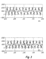
- Figs. 3 and 4 illustrate minor edge-wise vibrations superposing the rotation of the rotor which is about one sixth of the edge-wise natural frequency of the blade,
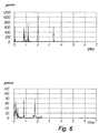
- Figs. 5-9 show examples of frequency analyses indicating various natural frequencies including the natural frequency of the blades,
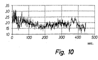
- Figs. 10-12 show an example of connected values of wind speed, transducer signal and Fourier-transformed transducer signal.
-
- Each
wind turbine blade 1 may be subjected to both edge-wise and flap-wise vibrations, confer Fig. 1. A black box is provided in eachblade 1 for detecting said vibrations and for detecting and registering various stresses in the blade. These stresses are measured by means of sensors in form of transducers. The measured signals from thetransducers 2 may be processed directly in the black box. Based on the processed and registered signals, it may subsequently be established whether thewind turbine blade 1 has been detrimentally overloaded. - The black box comprises
- an independent power supply operating in a rotating system,
- a number of dedicated sensors in form of accelerometers for indicating the stresses to which the blade is subjected,
- a data logger, in which the signals from the accelerometers are processed according to dedicated principles and stored, and
- a radio transmitter for transmitting key parameters from the signal processing to a receiver.
- The black box is mounted such in the blade to allow maintenance and furthermore adapted to allow the sensor to operate in the optimum manner.
- The power supply to the black box consists of a charger and a battery. The charger may be formed in several different manners and may utilise for instance the rotation of the blade as a source of energy. Optionally solar panels mounted on the surface of the blade or air currents around the blade may be used by means of a small turbine, or electrical power may be transmitted from the generator operated by the wind turbine.
- The data logger in the black box comprises a data collection unit with analogue and digital inputs/outputs, a signal conditioning unit with an anti-aliasing filter and a data processing unit. The data processing unit sorts the collected data pursuant to predetermined criteria such as set limit values. The data are stored in the data logger such that the temporal course subsequently may be evaluated. At a breakdown of the wind turbine, the data logger discontinues all logging to avoid deletion of the data which possibly may indicate the reason for the breakdown.
- The data logger furthermore has a communication port communicating with a wireless transmitting/receiving equipment such as a GSM telephone with data communications speed. Following predetermined regulations, the transmitter may be activated to transmit a message to a predetermined receiver, eg a predetermined telephone number. Moreover the transmitting/receiving equipment enables remote data switching exchange for reprogramming of the data collection unit.
- The receiver may communicate with a controller of the wind turbine, whereby the controller receives information about any overloads of the individual blade and may act thereon. The receiver may optionally communicate with a central monitoring unit or a service team which can be called out, if necessary.
- By measuring the accelerations in the edge-wise direction of the
blade 1, edge-wise vibrations, a too sudden application of the brakes and short circuits in the generator may be indicated. Due to the rotation of the blade, an acceleration signal of ± 1 g varying with the frequency of rotation is always present. The acceleration signal may be used either to calibrate the measurements and continuously automatically adjust the zero or to calibrate the collected measuring data. The data processing unit calculates the edge--wise natural frequency of the blade and checks that said frequency does not change drastically within a short time. A rapid change in the natural frequency indicates an overload and a possible fracture of a blade. Furthermore an unbalance in the rotor for instance due to ice formation may be registered for activation of a de-icing system. - The accelerations are also measured in the flap-wise direction of the blade. An overload in the flap-wise direction of the blade indicates that the maximum power has been exceeded or during standstill of the turbine that the wind speed has exceeded the threshold for operation. It is also possible to calibrate signals for measuring accelerations in the flap-wise direction provided the accelerometer is arranged so as to be influenced by a component of gravity corresponding to a slightly oblique arrangement of the accelerometer. Also in the flap-wise direction the data processing unit is able to continuously calculate the flap-wise natural frequency.
- Moreover the accelerations are measured in the longitudinal direction of the
blade 1 so as to indicate when the maximum allowable rpm has been exceeded by the rotor. This measurement may also be calibrated based on the periodical influence of the gravity. - The accelerometers may advantageously be arranged in the black boxes.
- A lightning indicator may reduce the damage due to lightning by rapid service and inspection. Such an indicator may also be used to settle a dispute between the owner of the wind turbine and the insurance company insuring the wind turbine.
- Furthermore the temperature may be indicated during operation.
- Moreover oil pressure transducers may indicate how the tip brake system has been used and thus reveal any overload of said brake system.
- By arranging a strain gauge in the base of the turbine, the loads to which the blade has been subjected during operation and during standstill are also indicated. The natural frequencies and amplitudes of the blade may also be read.
- Furthermore an anemometer may be provided for indicating the wind speed in the measuring period in question.
- The said black box comprising the three axis accelerometer may for instance be a G-LOGGER(tm) ACCELERATION ACQUISITION SYSTEM, Model 3310 from Silicon Designs, Inc., 1445-NW Mall Street, Issaquah, WA 98027-5344, USA.
- This black box is battery powered and can acquire data with a frequency range of 0 to 500 Hz. It comprises three orthogonally mounted model 1010J digital capacitive accelerometers along with microcomputer-based data logging electronics inside an aluminium case. The black box automatically logs AC/DC accelerations or AC velocities into its flash memory. Peak accelerations or velocity samples for each axis can also be recorded over user-selected time intervals. Multiple windows of contiguous acceleration samples can also be recorded, centre triggered, by acceleration peaks events. For AC acceleration or velocity, a root means squared (RMS) algorithm can be applied to the data stream. The overall size of the black box is 3.5"x 4.5"x 2.2" (8,89 cm x 11,43 cm x 5,58 cm) and the weight of the black box is about 28.5 oz (0,8 kg).
- The black box model No 3310 is easily programmed via a menu-based program running under Windows 95 on a personal computer. Missions are downloaded to the black box model No 3310 via a RS-232 serial cable connected to the serial port of the PC. Once programmed, the black box model No 3310 can be disconnected from the RS-232 serial cable and moved to the data collection site. An AC power adaptor is included to power the black box model No 3310 during mission programming and data downloading. Missions can be programmed with either immediate, absolute time/date or delayed starting points with sequentially programmable data types and independent time durations. The total data acquisition time depends on the acquisition rates selected and varies from 300 seconds to two weeks. The data sample rate ranges from one per second to 4000 per second. The black box may optionally be mounted to the object by means of screws.
- According to a particularly advantageous embodiment, two accelerometers are used, each with two axes.
- By measuring the acceleration in the edge-wise direction of the
blade 1. edge-wise vibrations, a too sudden application of the brakes and short circuits in the generator may be indicated. Due to the rotation of the blade, an acceleration signal of ± 1g varying with the frequency of rotation is always present. This acceleration signal may be used to calibrate the measurement and continuously automatically adjust the zero or to calibrate the collected measuring data. The data processing unit is able to calculate the edge-wise natural frequency of the blade and to check that said frequency does not change drastically within a short time. Such a drastic change in the natural . frequency may in fact indicate a fracture or an overload of the blade. - The acceleration is also measured in the flap-wise direction of the
blade 1. An overload in the flap-wise direction indicates that the threshold for maximum power has been exceeded or if the turbine is in standstill the survival wind speed. It is also possible to calibrate in the flap-wise direction provided the accelerometer is arranged such that a component of the gravity influences the accelerometer. This corresponds to an oblique arrangement of the accelerometer. Two axes are used for measuring this signal. Also in the flap-wise direction the data processing unit is able to continuously calculate the flap-wise natural frequency. - The acceleration is also measurable in the longitudinal direction of the blade to indicate whether the rotor has exceeded the maximum allowed rpm. This rpm value may be calibrated based on gravity.
- The black box is typically mounted on one of the beams joining the plates. The positioning may vary according to the size of the
blade 1. The optimum position on a blade of the LM 19.1 type is five to eight metres from the flange of the blade.
Claims (7)
- Wind turbine having a number of blades, a transducer being provided on at least one of the blades, characterised in that said transducer is a tri-axial sensor and preferably formed of a tri-axial accelerometer, said transducer being provided for indicating the stresses to which the blade has been subjected.
- Wind turbine according to claim 1, characterised in that the signals rendered by the transducer are transmitted to a signal processing unit, in which they are compared to known references or known signal patterns for indicating possible deviations therefrom.
- Wind turbine according to claim 2, characterised in that the signal processing unit is adapted to transmit a warning signal in case the deviations from the known references or known signal patterns exceed a predetermined threshold.
- Wind turbine according to claims 1-3, characterised in that the transducer is arranged adjacent or in one end of the blade.
- Wind turbine according to claims 1-4, characterised in that the signal processing unit is arranged centrally and communicates with each transducer optionally via wireless transmissions.
- Wind turbine according to any one of the preceding claims, characterised in that the tri-axial sensor is formed of two bi-axial accelerometers.
- Method of measuring vibrations in a wind turbine blade, characterised in that the measuring values are obtained from a tri-axial sensor provided on the blade for indicating the stresses to which the blade has been subjected.
Applications Claiming Priority (3)
| Application Number | Priority Date | Filing Date | Title |
|---|---|---|---|
| DK58998 | 1998-04-30 | ||
| DK199800589A DK58998A (en) | 1998-04-30 | 1998-04-30 | Windmill |
| PCT/DK1999/000211 WO1999057435A1 (en) | 1998-04-30 | 1999-04-16 | Wind turbine with stress indicator |
Publications (2)
| Publication Number | Publication Date |
|---|---|
| EP1075600A1 EP1075600A1 (en) | 2001-02-14 |
| EP1075600B1 true EP1075600B1 (en) | 2002-08-07 |
Family
ID=8095283
Family Applications (1)
| Application Number | Title | Priority Date | Filing Date |
|---|---|---|---|
| EP99913121A Expired - Lifetime EP1075600B1 (en) | 1998-04-30 | 1999-04-16 | Wind turbine with stress indicator |
Country Status (7)
| Country | Link |
|---|---|
| EP (1) | EP1075600B1 (en) |
| AT (1) | ATE221959T1 (en) |
| AU (1) | AU3137999A (en) |
| DE (1) | DE69902455T2 (en) |
| DK (2) | DK58998A (en) |
| ES (1) | ES2182503T3 (en) |
| WO (1) | WO1999057435A1 (en) |
Cited By (7)
| Publication number | Priority date | Publication date | Assignee | Title |
|---|---|---|---|---|
| DE102007007047A1 (en) | 2007-02-08 | 2008-08-14 | Hottinger Baldwin Messtechnik Gmbh | Device for detecting vibrations or deflections of rotor blades of a wind turbine |
| WO2013041742A1 (en) * | 2011-04-08 | 2013-03-28 | Antonio Claveria Canal | Lightning conductor deionising electrostatic charge, for protecting blades of wind generators |
| DE102011116551A1 (en) * | 2011-10-21 | 2013-04-25 | Baumer Electric Ag | Method for measuring deformation of rotor blade of wind-power plant, involves determining frequency range of mechanical natural oscillation of position detection device, and determining deformation of blade based on frequency range |
| CN104595112A (en) * | 2013-10-30 | 2015-05-06 | 通用电气公司 | Wind turbine and method for evaluating health status of blades thereon |
| US10107261B2 (en) | 2013-12-09 | 2018-10-23 | General Electric Company | System and method for reducing oscillation loads of wind turbine |
| DE102005016524B4 (en) | 2004-06-10 | 2022-01-13 | General Electric Company | Method and device for detecting rotor blade ice |
| EP3722596B1 (en) * | 2019-04-12 | 2023-07-19 | General Electric Company | System and method for mitigating damage in a rotor blade of a wind turbine |
Families Citing this family (53)
| Publication number | Priority date | Publication date | Assignee | Title |
|---|---|---|---|---|
| DE20021970U1 (en) * | 2000-12-30 | 2001-04-05 | Igus Ingenieurgemeinschaft Umweltschutz Meß-und Verfahrenstechnik GmbH, 01099 Dresden | Device for monitoring the condition of rotor blades on wind turbines |
| DE10219664A1 (en) * | 2002-04-19 | 2003-11-06 | Enron Wind Gmbh | Wind energy system has at least one, preferably each, rotor blade with sensor elements, preferably mounted as pairs, evaluation device producing load evaluation signals based on sensor element signals |
| WO2003104821A1 (en) * | 2002-05-22 | 2003-12-18 | Ratier-Figeac | Device for detecting impacts on aeronautic propeller blades |
| DE60212723D1 (en) * | 2002-05-31 | 2006-08-03 | Ratier Figeac Soc | DEVICE FOR DETERMINING IMPACT ON A PLANE PROPELLER |
| DE10323785B4 (en) | 2003-05-23 | 2009-09-10 | Wobben, Aloys, Dipl.-Ing. | Method for detecting an ice accumulation on rotor blades |
| DE10331160A1 (en) * | 2003-07-10 | 2005-02-03 | Könnemann, Frank | Gravitational force impact generator for wind turbine rotor blade testing has impact body incorporated within rotor blade for providing impact force during blade rotation |
| ATE352057T1 (en) | 2003-11-14 | 2007-02-15 | Gamesa Eolica S A Soc Uniperso | MONITORING AND DATA PROCESSING UNIT FOR WIND TURBS AND SYSTEM FOR PREVENTIVE MAINTENANCE FOR WIND TURBIES |
| EP1531376B1 (en) * | 2003-11-14 | 2007-01-17 | Gamesa Eolica, S.A. (Sociedad Unipersonal) | Monitoring and data processing equipment for wind turbines and predictive maintenance system for wind power stations |
| DK177602B1 (en) * | 2004-01-16 | 2013-11-18 | Lm Wind Power As | Monitoring the operation of a wind power plant |
| DE102005017054B4 (en) | 2004-07-28 | 2012-01-05 | Igus - Innovative Technische Systeme Gmbh | Method and device for monitoring the condition of rotor blades on wind turbines |
| DE102005018996A1 (en) * | 2005-04-22 | 2006-10-26 | Repower Systems Ag | Control assembly for group of wind turbines has cable series-link between computer and turbines and backup wireless link |
| US7348683B2 (en) * | 2005-11-17 | 2008-03-25 | General Electric Company | Rotor for a wind energy turbine |
| WO2007089136A2 (en) * | 2006-02-03 | 2007-08-09 | Pantheon Bv | Wind turbine tower vibration damping |
| ES2355312T3 (en) * | 2006-03-15 | 2011-03-24 | Siemens Aktiengesellschaft | WIND TURBINE AND PROCEDURE TO DETERMINE AT LEAST A ROTATION PARAMETER OF A WIND TURBINE ROTOR. |
| DE102006036157B4 (en) | 2006-08-01 | 2016-09-15 | Senvion Gmbh | calibration |
| CN101589229B (en) | 2006-12-08 | 2011-11-16 | 维斯塔斯风力系统有限公司 | Method of attenuating edge oscillations in one or more blades of a wind turbine, active stall controlled wind turbine and use thereof |
| CN101675325A (en) | 2007-03-29 | 2010-03-17 | 维斯塔斯风力系统有限公司 | Be used to check the method for at least one spinner blade of wind turbine and the check system that is used at least one spinner blade of wind turbine |
| DE102007020423A1 (en) * | 2007-04-27 | 2008-10-30 | Daubner & Stommel GbR Bau-Werk-Planung (vertretungsberechtigter Gesellschafter: Matthias Stommel, 27777 Ganderkesee) | Method for operating a wind turbine and wind turbine |
| GB2448940B (en) * | 2007-05-04 | 2009-10-14 | Insensys Ltd | Wind turbine monitoring |
| DK200701144A (en) | 2007-08-13 | 2009-02-14 | Siemens Wind Power As | Monitoring of blade frequencies of a wind turbine |
| DK2037212T3 (en) | 2007-09-12 | 2016-03-29 | Siemens Ag | Method and sensor device for determining bending and / or load |
| ES2337645B1 (en) * | 2007-09-14 | 2011-03-11 | GAMESA INNOVATION & TECHNOLOGY, S.L. | SENSORIZED SHOVEL UNION. |
| DK200701456A (en) | 2007-10-09 | 2009-04-10 | Siemens Wind Power As | Monitoring of a wind turbine's wing frequencies |
| WO2009068020A2 (en) * | 2007-11-30 | 2009-06-04 | Innovative Windpower Ag | Method for regulating the electrical load of a wind power system |
| EP2108830B1 (en) * | 2008-01-10 | 2019-08-28 | Siemens Gamesa Renewable Energy A/S | Method for determining fatigue load of a wind turbine and for fatigue load control, and wind turbines therefor |
| US8718831B2 (en) * | 2008-05-09 | 2014-05-06 | General Electric Company | Methods and apparatus for sensing parameters of rotating blades |
| CA2724311A1 (en) | 2008-05-13 | 2009-11-19 | Purdue Research Foundation | Monitoring of wind turbines |
| WO2010046403A2 (en) | 2008-10-23 | 2010-04-29 | Vestas Wind Systems A/S | A wind turbine and a method for monitoring a wind turbine |
| US8186950B2 (en) * | 2008-12-23 | 2012-05-29 | General Electric Company | Aerodynamic device for detection of wind turbine blade operation |
| US8137066B2 (en) * | 2009-04-16 | 2012-03-20 | Frontier Wind, Llc | Pressure based load measurement |
| WO2010123461A1 (en) * | 2009-04-21 | 2010-10-28 | Vestas Wind Systems A/S | A wind turbine comprising a rotor |
| US7896613B2 (en) * | 2009-06-03 | 2011-03-01 | General Electric Company | System and method for wind turbine noise control and damage detection |
| US8222757B2 (en) * | 2009-06-05 | 2012-07-17 | General Electric Company | Load identification system and method of assembling the same |
| US8070439B2 (en) * | 2009-10-29 | 2011-12-06 | General Electric Company | Systems and methods for testing a wind turbine pitch control system |
| CN101839216B (en) * | 2010-05-11 | 2015-04-01 | 无锡风电设计研究院有限公司 | Intelligent blade of wind power generator with strain sensors |
| US8222760B2 (en) | 2010-06-29 | 2012-07-17 | General Electric Company | Method for controlling a proximity sensor of a wind turbine |
| ES2391734B1 (en) * | 2010-06-30 | 2013-10-09 | Gamesa Innovation & Technology, S.L. | SENSORIZATION SYSTEM OF A SHOVEL. |
| DE102010032120A1 (en) * | 2010-07-24 | 2012-01-26 | Robert Bosch Gmbh | Method and device for determining a bending angle of a rotor blade of a wind turbine |
| EP2472238A1 (en) * | 2010-12-29 | 2012-07-04 | Siemens Aktiengesellschaft | Determination of a vibrational frequency of a wind turbine rotor blade with a sensor device being placed at a structural component being assigned to and/or being part of the rotor |
| US8786118B2 (en) * | 2011-07-22 | 2014-07-22 | Robert Bosch Gmbh | Energy-efficient wireless communication scheme for wind turbines |
| DE102011116961B4 (en) * | 2011-10-26 | 2024-06-27 | Weidmüller Monitoring Systems Gmbh | Method for determining mechanical damage to a rotor blade of a wind turbine |
| CN104246466B (en) * | 2011-12-30 | 2018-01-02 | 维斯塔斯风力系统集团公司 | Estimating and controlling the load experienced in a structure |
| FR2986864B1 (en) * | 2012-02-14 | 2014-02-28 | Snecma | METHOD OF MEASURING THE DEFORMATION OF A TURBOMACHINE BLADE DURING THE OPERATION OF THE TURBOMACHINE |
| DE102013014622A1 (en) * | 2013-09-02 | 2015-03-05 | Northrop Grumman Litef Gmbh | System and method for determining movements and vibrations of moving structures |
| CN103629044B (en) * | 2013-12-18 | 2016-08-31 | 中国科学院工程热物理研究所 | A kind of leaf and root structure of Blades For Horizontal Axis Wind |
| FR3015798B1 (en) | 2013-12-20 | 2016-01-22 | Ratier Figeac Soc | DEVICE FOR THE INDEPENDENT TRANSMISSION OF MULTIPLE ELECTRIC POWER TO A TURBOMACHINE ROTOR |
| JP6142074B2 (en) * | 2014-03-19 | 2017-06-07 | 株式会社日立製作所 | Fatigue testing equipment |
| DK201400518A1 (en) * | 2014-09-11 | 2015-08-24 | Wind Solutions As Kk | Wind turbine blade sensor device |
| US20170051725A1 (en) * | 2015-08-21 | 2017-02-23 | National Taiwan University | Method and apparatus for diagnosing blades of wind turbine |
| EP3232051A1 (en) * | 2016-04-13 | 2017-10-18 | Vihriälä, Harri | Method and device for loading detection of blade of wind power turbine |
| ES2934717T3 (en) * | 2016-06-13 | 2023-02-24 | Vestas Wind Sys As | Vibration damping of wind turbine blades in the direction of the edge |
| DE102017115927A1 (en) | 2017-07-14 | 2019-01-17 | fos4X GmbH | Strain and vibration measuring system for monitoring rotor blades |
| CN110486236B (en) * | 2019-08-08 | 2021-01-12 | 北京汉能华科技股份有限公司 | Fault detection method and system for wind driven generator |
Family Cites Families (3)
| Publication number | Priority date | Publication date | Assignee | Title |
|---|---|---|---|---|
| US4143552A (en) * | 1978-03-01 | 1979-03-13 | General Electric Company | Coal seam sensor |
| US4524620A (en) * | 1983-02-07 | 1985-06-25 | Hughes Helicopters, Inc. | In-flight monitoring of composite structural components such as helicopter rotor blades |
| JPH0754762A (en) * | 1993-08-11 | 1995-02-28 | Railway Technical Res Inst | Wind turbine generator for magnetic levitation vehicle |
-
1998
- 1998-04-30 DK DK199800589A patent/DK58998A/en not_active Application Discontinuation
-
1999
- 1999-04-16 WO PCT/DK1999/000211 patent/WO1999057435A1/en not_active Ceased
- 1999-04-16 AT AT99913121T patent/ATE221959T1/en not_active IP Right Cessation
- 1999-04-16 DE DE69902455T patent/DE69902455T2/en not_active Expired - Lifetime
- 1999-04-16 DK DK99913121T patent/DK1075600T3/en active
- 1999-04-16 AU AU31379/99A patent/AU3137999A/en not_active Abandoned
- 1999-04-16 EP EP99913121A patent/EP1075600B1/en not_active Expired - Lifetime
- 1999-04-16 ES ES99913121T patent/ES2182503T3/en not_active Expired - Lifetime
Cited By (8)
| Publication number | Priority date | Publication date | Assignee | Title |
|---|---|---|---|---|
| DE102005016524B4 (en) | 2004-06-10 | 2022-01-13 | General Electric Company | Method and device for detecting rotor blade ice |
| DE102007007047A1 (en) | 2007-02-08 | 2008-08-14 | Hottinger Baldwin Messtechnik Gmbh | Device for detecting vibrations or deflections of rotor blades of a wind turbine |
| WO2013041742A1 (en) * | 2011-04-08 | 2013-03-28 | Antonio Claveria Canal | Lightning conductor deionising electrostatic charge, for protecting blades of wind generators |
| DE102011116551A1 (en) * | 2011-10-21 | 2013-04-25 | Baumer Electric Ag | Method for measuring deformation of rotor blade of wind-power plant, involves determining frequency range of mechanical natural oscillation of position detection device, and determining deformation of blade based on frequency range |
| CN104595112A (en) * | 2013-10-30 | 2015-05-06 | 通用电气公司 | Wind turbine and method for evaluating health status of blades thereon |
| CN104595112B (en) * | 2013-10-30 | 2018-01-16 | 通用电气公司 | Wind turbine and the method for assessing its blade health status |
| US10107261B2 (en) | 2013-12-09 | 2018-10-23 | General Electric Company | System and method for reducing oscillation loads of wind turbine |
| EP3722596B1 (en) * | 2019-04-12 | 2023-07-19 | General Electric Company | System and method for mitigating damage in a rotor blade of a wind turbine |
Also Published As
| Publication number | Publication date |
|---|---|
| EP1075600A1 (en) | 2001-02-14 |
| DK1075600T3 (en) | 2002-12-02 |
| AU3137999A (en) | 1999-11-23 |
| DK58998A (en) | 1999-10-31 |
| ATE221959T1 (en) | 2002-08-15 |
| DE69902455T2 (en) | 2003-05-08 |
| WO1999057435A1 (en) | 1999-11-11 |
| DE69902455D1 (en) | 2002-09-12 |
| ES2182503T3 (en) | 2003-03-01 |
Similar Documents
| Publication | Publication Date | Title |
|---|---|---|
| EP1075600A1 (en) | Wind turbine with stress indicator | |
| US8757003B1 (en) | Multi-frequency-band blade condition monitoring system | |
| US8511177B1 (en) | Blade condition monitoring system | |
| US9194843B2 (en) | Method and apparatus for monitoring wind turbine blades during operation | |
| EP1788240B1 (en) | Rotor for a wind energy turbine | |
| US8186950B2 (en) | Aerodynamic device for detection of wind turbine blade operation | |
| EP2108823A2 (en) | Independent sensing system for wind turbines | |
| US8847419B2 (en) | Control device for a wind turbine | |
| US10607424B2 (en) | Frequency-adaptable structural health and usage monitoring system (HUMS) and method with smart sensors | |
| EP2531724B1 (en) | Method and system for determining a mass change on a rotating blade of a wind turbine | |
| US20180331602A1 (en) | Shaft-mounted monitor for monitoring rotating machinery | |
| EP2610604B1 (en) | Method for oscillation measurement on rotor blades of wind power installations | |
| CA2414645A1 (en) | Method for determining the angle of a rotor blade pertaining to a wind energy installation | |
| CN102192086A (en) | System, device, and method for wind turbine load reduction in a cold weather environment | |
| CN114450483A (en) | Detection of abnormal conditions of wind turbine generator | |
| CN101476538B (en) | For individual blade noise measurement system and the method for wind turbine | |
| US7698959B2 (en) | Torque measurement device for measuring torque on rotatable shafts at high speeds | |
| CN115698503A (en) | Method and wind energy installation for condition monitoring of a powertrain or tower of a wind energy installation | |
| CN213063840U (en) | Crack monitoring equipment and systems for pitch bearings and wind turbines | |
| EP3317628B1 (en) | A method and a device for determining torsional deformation in a drivetrain | |
| Botta et al. | Effects of hostile terrains on wind turbine performances and loads: The Acqua Spruzza experience | |
| KR101365573B1 (en) | Method and system of detecting crack of wind turbine rotor blade | |
| Zayas et al. | 3X-100 blade field test. | |
| GB2354825A (en) | Plant condition monitoring using vibrational measurements | |
| CN212690235U (en) | Wind turbine generator system state monitoring protection device |
Legal Events
| Date | Code | Title | Description |
|---|---|---|---|
| PUAI | Public reference made under article 153(3) epc to a published international application that has entered the european phase |
Free format text: ORIGINAL CODE: 0009012 |
|
| 17P | Request for examination filed |
Effective date: 20000918 |
|
| AK | Designated contracting states |
Kind code of ref document: A1 Designated state(s): AT BE CH CY DE DK ES FI FR GB GR IE IT LI LU MC NL PT SE |
|
| GRAG | Despatch of communication of intention to grant |
Free format text: ORIGINAL CODE: EPIDOS AGRA |
|
| 17Q | First examination report despatched |
Effective date: 20010903 |
|
| GRAG | Despatch of communication of intention to grant |
Free format text: ORIGINAL CODE: EPIDOS AGRA |
|
| GRAG | Despatch of communication of intention to grant |
Free format text: ORIGINAL CODE: EPIDOS AGRA |
|
| GRAH | Despatch of communication of intention to grant a patent |
Free format text: ORIGINAL CODE: EPIDOS IGRA |
|
| GRAH | Despatch of communication of intention to grant a patent |
Free format text: ORIGINAL CODE: EPIDOS IGRA |
|
| GRAA | (expected) grant |
Free format text: ORIGINAL CODE: 0009210 |
|
| AK | Designated contracting states |
Kind code of ref document: B1 Designated state(s): AT BE CH CY DE DK ES FI FR GB GR IE IT LI LU MC NL PT SE |
|
| PG25 | Lapsed in a contracting state [announced via postgrant information from national office to epo] |
Ref country code: NL Free format text: LAPSE BECAUSE OF FAILURE TO SUBMIT A TRANSLATION OF THE DESCRIPTION OR TO PAY THE FEE WITHIN THE PRESCRIBED TIME-LIMIT Effective date: 20020807 Ref country code: LI Free format text: LAPSE BECAUSE OF FAILURE TO SUBMIT A TRANSLATION OF THE DESCRIPTION OR TO PAY THE FEE WITHIN THE PRESCRIBED TIME-LIMIT Effective date: 20020807 Ref country code: IT Free format text: LAPSE BECAUSE OF FAILURE TO SUBMIT A TRANSLATION OF THE DESCRIPTION OR TO PAY THE FEE WITHIN THE PRESCRIBED TIME-LIMIT;WARNING: LAPSES OF ITALIAN PATENTS WITH EFFECTIVE DATE BEFORE 2007 MAY HAVE OCCURRED AT ANY TIME BEFORE 2007. THE CORRECT EFFECTIVE DATE MAY BE DIFFERENT FROM THE ONE RECORDED. Effective date: 20020807 Ref country code: GR Free format text: LAPSE BECAUSE OF FAILURE TO SUBMIT A TRANSLATION OF THE DESCRIPTION OR TO PAY THE FEE WITHIN THE PRESCRIBED TIME-LIMIT Effective date: 20020807 Ref country code: FR Free format text: LAPSE BECAUSE OF NON-PAYMENT OF DUE FEES Effective date: 20020807 Ref country code: FI Free format text: LAPSE BECAUSE OF FAILURE TO SUBMIT A TRANSLATION OF THE DESCRIPTION OR TO PAY THE FEE WITHIN THE PRESCRIBED TIME-LIMIT Effective date: 20020807 Ref country code: CH Free format text: LAPSE BECAUSE OF FAILURE TO SUBMIT A TRANSLATION OF THE DESCRIPTION OR TO PAY THE FEE WITHIN THE PRESCRIBED TIME-LIMIT Effective date: 20020807 Ref country code: BE Free format text: LAPSE BECAUSE OF FAILURE TO SUBMIT A TRANSLATION OF THE DESCRIPTION OR TO PAY THE FEE WITHIN THE PRESCRIBED TIME-LIMIT Effective date: 20020807 Ref country code: AT Free format text: LAPSE BECAUSE OF FAILURE TO SUBMIT A TRANSLATION OF THE DESCRIPTION OR TO PAY THE FEE WITHIN THE PRESCRIBED TIME-LIMIT Effective date: 20020807 |
|
| REF | Corresponds to: |
Ref document number: 221959 Country of ref document: AT Date of ref document: 20020815 Kind code of ref document: T |
|
| REG | Reference to a national code |
Ref country code: GB Ref legal event code: FG4D |
|
| REG | Reference to a national code |
Ref country code: CH Ref legal event code: EP |
|
| REG | Reference to a national code |
Ref country code: IE Ref legal event code: FG4D |
|
| REF | Corresponds to: |
Ref document number: 69902455 Country of ref document: DE Date of ref document: 20020912 |
|
| PG25 | Lapsed in a contracting state [announced via postgrant information from national office to epo] |
Ref country code: SE Free format text: LAPSE BECAUSE OF FAILURE TO SUBMIT A TRANSLATION OF THE DESCRIPTION OR TO PAY THE FEE WITHIN THE PRESCRIBED TIME-LIMIT Effective date: 20021107 |
|
| PG25 | Lapsed in a contracting state [announced via postgrant information from national office to epo] |
Ref country code: PT Free format text: LAPSE BECAUSE OF FAILURE TO SUBMIT A TRANSLATION OF THE DESCRIPTION OR TO PAY THE FEE WITHIN THE PRESCRIBED TIME-LIMIT Effective date: 20021122 |
|
| REG | Reference to a national code |
Ref country code: DK Ref legal event code: T3 |
|
| NLV1 | Nl: lapsed or annulled due to failure to fulfill the requirements of art. 29p and 29m of the patents act | ||
| REG | Reference to a national code |
Ref country code: CH Ref legal event code: PL |
|
| REG | Reference to a national code |
Ref country code: ES Ref legal event code: FG2A Ref document number: 2182503 Country of ref document: ES Kind code of ref document: T3 |
|
| PG25 | Lapsed in a contracting state [announced via postgrant information from national office to epo] |
Ref country code: LU Free format text: LAPSE BECAUSE OF NON-PAYMENT OF DUE FEES Effective date: 20030416 Ref country code: IE Free format text: LAPSE BECAUSE OF NON-PAYMENT OF DUE FEES Effective date: 20030416 Ref country code: CY Free format text: LAPSE BECAUSE OF FAILURE TO SUBMIT A TRANSLATION OF THE DESCRIPTION OR TO PAY THE FEE WITHIN THE PRESCRIBED TIME-LIMIT Effective date: 20030416 |
|
| PG25 | Lapsed in a contracting state [announced via postgrant information from national office to epo] |
Ref country code: MC Free format text: LAPSE BECAUSE OF NON-PAYMENT OF DUE FEES Effective date: 20030430 |
|
| PLBE | No opposition filed within time limit |
Free format text: ORIGINAL CODE: 0009261 |
|
| STAA | Information on the status of an ep patent application or granted ep patent |
Free format text: STATUS: NO OPPOSITION FILED WITHIN TIME LIMIT |
|
| 26N | No opposition filed |
Effective date: 20030508 |
|
| REG | Reference to a national code |
Ref country code: IE Ref legal event code: MM4A |
|
| PGFP | Annual fee paid to national office [announced via postgrant information from national office to epo] |
Ref country code: DK Payment date: 20180426 Year of fee payment: 20 Ref country code: ES Payment date: 20180503 Year of fee payment: 20 Ref country code: DE Payment date: 20180427 Year of fee payment: 20 |
|
| PGFP | Annual fee paid to national office [announced via postgrant information from national office to epo] |
Ref country code: GB Payment date: 20180427 Year of fee payment: 20 |
|
| REG | Reference to a national code |
Ref country code: DE Ref legal event code: R071 Ref document number: 69902455 Country of ref document: DE |
|
| REG | Reference to a national code |
Ref country code: DK Ref legal event code: EUP Effective date: 20190416 |
|
| REG | Reference to a national code |
Ref country code: GB Ref legal event code: PE20 Expiry date: 20190415 |
|
| PG25 | Lapsed in a contracting state [announced via postgrant information from national office to epo] |
Ref country code: GB Free format text: LAPSE BECAUSE OF EXPIRATION OF PROTECTION Effective date: 20190415 |
|
| REG | Reference to a national code |
Ref country code: ES Ref legal event code: FD2A Effective date: 20200904 |
|
| PG25 | Lapsed in a contracting state [announced via postgrant information from national office to epo] |
Ref country code: ES Free format text: LAPSE BECAUSE OF EXPIRATION OF PROTECTION Effective date: 20190417 |
|
| P01 | Opt-out of the competence of the unified patent court (upc) registered |
Effective date: 20230522 |