EP1075583B1 - Shaped-charge liner - Google Patents
Shaped-charge liner Download PDFInfo
- Publication number
- EP1075583B1 EP1075583B1 EP99962642A EP99962642A EP1075583B1 EP 1075583 B1 EP1075583 B1 EP 1075583B1 EP 99962642 A EP99962642 A EP 99962642A EP 99962642 A EP99962642 A EP 99962642A EP 1075583 B1 EP1075583 B1 EP 1075583B1
- Authority
- EP
- European Patent Office
- Prior art keywords
- liner
- metal mixture
- molybdenum
- charge
- tungsten
- Prior art date
- Legal status (The legal status is an assumption and is not a legal conclusion. Google has not performed a legal analysis and makes no representation as to the accuracy of the status listed.)
- Expired - Lifetime
Links
- 229910052751 metal Inorganic materials 0.000 claims description 33
- 239000002184 metal Substances 0.000 claims description 33
- 239000000203 mixture Substances 0.000 claims description 33
- 229910052750 molybdenum Inorganic materials 0.000 claims description 33
- 239000000463 material Substances 0.000 claims description 27
- ZOKXTWBITQBERF-UHFFFAOYSA-N Molybdenum Chemical compound [Mo] ZOKXTWBITQBERF-UHFFFAOYSA-N 0.000 claims description 25
- 239000011733 molybdenum Substances 0.000 claims description 25
- 229910052721 tungsten Inorganic materials 0.000 claims description 25
- WFKWXMTUELFFGS-UHFFFAOYSA-N tungsten Chemical compound [W] WFKWXMTUELFFGS-UHFFFAOYSA-N 0.000 claims description 24
- 239000010937 tungsten Substances 0.000 claims description 23
- 239000002360 explosive Substances 0.000 claims description 12
- 238000000034 method Methods 0.000 claims description 10
- 239000012255 powdered metal Substances 0.000 claims description 7
- 230000035939 shock Effects 0.000 claims description 7
- 239000007787 solid Substances 0.000 claims description 3
- 230000006835 compression Effects 0.000 claims 2
- 238000007906 compression Methods 0.000 claims 2
- 238000005461 lubrication Methods 0.000 claims 2
- 230000015572 biosynthetic process Effects 0.000 description 17
- 238000005755 formation reaction Methods 0.000 description 17
- 150000002739 metals Chemical class 0.000 description 11
- 230000035515 penetration Effects 0.000 description 10
- 238000009491 slugging Methods 0.000 description 9
- 239000011159 matrix material Substances 0.000 description 8
- OKTJSMMVPCPJKN-UHFFFAOYSA-N Carbon Chemical compound [C] OKTJSMMVPCPJKN-UHFFFAOYSA-N 0.000 description 7
- 239000010949 copper Substances 0.000 description 7
- 229910002804 graphite Inorganic materials 0.000 description 7
- 239000010439 graphite Substances 0.000 description 7
- 229910052802 copper Inorganic materials 0.000 description 6
- RYGMFSIKBFXOCR-UHFFFAOYSA-N Copper Chemical compound [Cu] RYGMFSIKBFXOCR-UHFFFAOYSA-N 0.000 description 5
- 239000011133 lead Substances 0.000 description 5
- PXHVJJICTQNCMI-UHFFFAOYSA-N Nickel Chemical compound [Ni] PXHVJJICTQNCMI-UHFFFAOYSA-N 0.000 description 4
- 238000005054 agglomeration Methods 0.000 description 4
- 230000008901 benefit Effects 0.000 description 4
- 230000000694 effects Effects 0.000 description 3
- 241000237858 Gastropoda Species 0.000 description 2
- XEEYBQQBJWHFJM-UHFFFAOYSA-N Iron Chemical compound [Fe] XEEYBQQBJWHFJM-UHFFFAOYSA-N 0.000 description 2
- ATJFFYVFTNAWJD-UHFFFAOYSA-N Tin Chemical compound [Sn] ATJFFYVFTNAWJD-UHFFFAOYSA-N 0.000 description 2
- 229910052770 Uranium Inorganic materials 0.000 description 2
- 239000011230 binding agent Substances 0.000 description 2
- 239000000470 constituent Substances 0.000 description 2
- 230000003247 decreasing effect Effects 0.000 description 2
- 239000000314 lubricant Substances 0.000 description 2
- 230000001050 lubricating effect Effects 0.000 description 2
- 238000012986 modification Methods 0.000 description 2
- 230000004048 modification Effects 0.000 description 2
- 229910052759 nickel Inorganic materials 0.000 description 2
- 229910052715 tantalum Inorganic materials 0.000 description 2
- 239000011135 tin Substances 0.000 description 2
- 229910052718 tin Inorganic materials 0.000 description 2
- 229910000838 Al alloy Inorganic materials 0.000 description 1
- 229910000906 Bronze Inorganic materials 0.000 description 1
- 244000000626 Daucus carota Species 0.000 description 1
- 235000002767 Daucus carota Nutrition 0.000 description 1
- BQCADISMDOOEFD-UHFFFAOYSA-N Silver Chemical compound [Ag] BQCADISMDOOEFD-UHFFFAOYSA-N 0.000 description 1
- 229910000831 Steel Inorganic materials 0.000 description 1
- HCHKCACWOHOZIP-UHFFFAOYSA-N Zinc Chemical compound [Zn] HCHKCACWOHOZIP-UHFFFAOYSA-N 0.000 description 1
- 229910001297 Zn alloy Inorganic materials 0.000 description 1
- 229910045601 alloy Inorganic materials 0.000 description 1
- 239000000956 alloy Substances 0.000 description 1
- XAGFODPZIPBFFR-UHFFFAOYSA-N aluminium Chemical compound [Al] XAGFODPZIPBFFR-UHFFFAOYSA-N 0.000 description 1
- 229910052787 antimony Inorganic materials 0.000 description 1
- WATWJIUSRGPENY-UHFFFAOYSA-N antimony atom Chemical compound [Sb] WATWJIUSRGPENY-UHFFFAOYSA-N 0.000 description 1
- 239000010974 bronze Substances 0.000 description 1
- 229910052799 carbon Inorganic materials 0.000 description 1
- 239000004568 cement Substances 0.000 description 1
- 229910017052 cobalt Inorganic materials 0.000 description 1
- 239000010941 cobalt Substances 0.000 description 1
- GUTLYIVDDKVIGB-UHFFFAOYSA-N cobalt atom Chemical compound [Co] GUTLYIVDDKVIGB-UHFFFAOYSA-N 0.000 description 1
- KUNSUQLRTQLHQQ-UHFFFAOYSA-N copper tin Chemical compound [Cu].[Sn] KUNSUQLRTQLHQQ-UHFFFAOYSA-N 0.000 description 1
- 238000005474 detonation Methods 0.000 description 1
- 210000005069 ears Anatomy 0.000 description 1
- 230000008030 elimination Effects 0.000 description 1
- 238000003379 elimination reaction Methods 0.000 description 1
- PCHJSUWPFVWCPO-UHFFFAOYSA-N gold Chemical compound [Au] PCHJSUWPFVWCPO-UHFFFAOYSA-N 0.000 description 1
- 229910052737 gold Inorganic materials 0.000 description 1
- 239000010931 gold Substances 0.000 description 1
- 239000008240 homogeneous mixture Substances 0.000 description 1
- 229930195733 hydrocarbon Natural products 0.000 description 1
- 150000002430 hydrocarbons Chemical class 0.000 description 1
- 229910052742 iron Inorganic materials 0.000 description 1
- 239000012768 molten material Substances 0.000 description 1
- 239000000843 powder Substances 0.000 description 1
- 238000011084 recovery Methods 0.000 description 1
- 229910052709 silver Inorganic materials 0.000 description 1
- 239000004332 silver Substances 0.000 description 1
- 239000010959 steel Substances 0.000 description 1
- GUVRBAGPIYLISA-UHFFFAOYSA-N tantalum atom Chemical compound [Ta] GUVRBAGPIYLISA-UHFFFAOYSA-N 0.000 description 1
- JFALSRSLKYAFGM-UHFFFAOYSA-N uranium(0) Chemical compound [U] JFALSRSLKYAFGM-UHFFFAOYSA-N 0.000 description 1
- 229910052725 zinc Inorganic materials 0.000 description 1
- 239000011701 zinc Substances 0.000 description 1
Images

Classifications
-
- F—MECHANICAL ENGINEERING; LIGHTING; HEATING; WEAPONS; BLASTING
- F42—AMMUNITION; BLASTING
- F42B—EXPLOSIVE CHARGES, e.g. FOR BLASTING, FIREWORKS, AMMUNITION
- F42B1/00—Explosive charges characterised by form or shape but not dependent on shape of container
- F42B1/02—Shaped or hollow charges
- F42B1/032—Shaped or hollow charges characterised by the material of the liner
-
- E—FIXED CONSTRUCTIONS
- E21—EARTH OR ROCK DRILLING; MINING
- E21B—EARTH OR ROCK DRILLING; OBTAINING OIL, GAS, WATER, SOLUBLE OR MELTABLE MATERIALS OR A SLURRY OF MINERALS FROM WELLS
- E21B43/00—Methods or apparatus for obtaining oil, gas, water, soluble or meltable materials or a slurry of minerals from wells
- E21B43/11—Perforators; Permeators
- E21B43/116—Gun or shaped-charge perforators
- E21B43/117—Shaped-charge perforators
Definitions
- the present invention concerns a perforated gun according to the precharacterizing portion of claim 1 and a method of perforating a well according to the precharacterizing portion of claim 8.
- This invention relates to shaped explosive charges, and in particular to a liner material used in shaped charges, such as those used in oil and gas wells.
- Shaped charges for use in oil and gas well perforation and retrieval operations typically will consist of a casing which houses a quantity of explosive and a liner formed from a compressed-powder metal mixture.
- Materials used for such liners are well known and include copper, graphite, tungsten, lead, nickel and tin. The purpose of these metals is to allow a reasonably homogeneous mixture with specific properties.
- the density and symmetry of the liner can be controlled.
- the material components i.e. the material percentages in the matrix, the performance can be controlled.
- the US-A-5279228 discloses a shaped charge perforator, comprising:
- a metallic liner is used made of an alloy containing Ta in an amount sufficient to have a density higher than that of copper.
- An object of the present invention is therefore to provide a means of making a high density charge lining without the disadvantages of slug formation.
- Another object of the present invention is to provided a charge liner material comprising at least molybdenum (Mo) and other materials of higher density such as tungsten (W).
- Mo molybdenum
- W tungsten
- Yet another object of the present invention is to provide an improved shaped-charge for forming perforations in a wellbore.
- the perforating gun of the present invention is defined in the characterizing portion of claim 1 and the method of perforating a well according to the present invention is defined in the characterizing portion of claim 8.
- a liner material for use in a shaped explosive charge, such as those used in oil and gas wells for perforating formations surrounding the borehole of the well.
- the liner material is formed from a powdered metal mixture that contains molybdenum.
- the metal mixture may further contain 10 tungsten and other powdered metals.
- the liner material contains an amount of molybdenum of between about 0.5% to 25% by weight of the metal mixture, with tungsten making up between about 40% to 85% by weight of the metal mixture.
- the mixture may also contain graphite.
- the liner may be formed in a shaped charge having a casing.
- the casing has a casing wall and a hollow interior.
- the liner is positioned within the interior of the casing, and an explosive material is disposed within the interior of the casing between the casing wall and the liner.
- the liner may be formed in a generally conical configuration.
- the force of the detonation collapses the liner material and ejects it from one end of the charge.
- the ejected material is a "jet", which penetrates the casing, the cement around the casing, and a quantity of the formation. It is desirable to penetrate as much of the formation as possible to obtain the highest yield of oil or gas.
- the jet formation is critical to the operation of the shaped charge. While a high density material such as tungsten gives deeper penetration into the formation, it also creates slugs that block the perforation. This is due to a re-agglomeration of the molten material instead of dispersal.
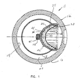
- FIG. 1 a transverse cross section of a perforating gun assembly 10 of the present invention is shown.
- Figure 2 shows a longitudinal cross section of the perforating gun assembly 10.
- the perforating gun 10 has a tubular carrier 12 having an interior cylinder wall 14 and an exterior cylindrical surface or wall 16.
- a cylindrical charge tube 18 is disposed within the tubular carrier 12 and is concentric with the tubular carrier 12.
- the outside diameter of the charge tube 18 is such that an annular space 20 is created between the outer surface of the charge tube 18 and the inner wall 14 of the carrier 12.
- An explosive shaped charge 22 has a frusto-conical charge case 24.
- the charge case 24 is typically formed from steel, die cast aluminum, or zinc alloys and has an interior surface or wall 26 that defines a hollow interior of the charge case 24.
- the charge case 24 is open at the outer end and tapers inward.
- Disposed within the interior of the case 24 is a liner 28 having a generally conical or frusto-conical configuration.
- the liner 28 tapers inward from a base 30, located at the outer end, to a nose portion 32.
- the liner 28 is open at the base 30 and has a hollow interior.
- the liner 28 is formed from a powdered metal matrix that is compressed under high pressure to the desired configuration and density.
- the explosive material 34 extends from the interior of the case 24 through channel 36 formed in the innermost end of the case 24.
- a pair of ears 38 extend from the channel 36 of the case 24 and receive a detonating cord 40 for detonating the explosive 34 of the shaped charge 22.
- a plurality of shaped charges 22 are mounted in the charge tube 18 and the perforating gun assembly 10 is mounted within a wellbore (not shown).
- the liner 28 disintegrates forming a jet that penetrates through the casing (not shown) of the wellbore and into the surrounding formation to form a perforation.
- the liner 28 is formed from a powdered metal mixture that is compressed at high pressures to form a solid mass in the desired shape.
- a high density metal must be included in the mixture in order to achieve the desired effect from the explosive force.
- Common high density metals used include copper and tungsten, but other high density metals can also be used.
- the mixture of metals typically contains various other ductile metals being combined within the matrix to serve as a binder material.
- Other binder metals include nickel, lead, silver, gold, zinc, iron, tin, antimony, tantalum, cobalt, bronze and uranium. Powdered graphite is also commonly used and serves as lubricant during the formation of the liner.
- molybdenum has been found to have higher shock velocities than conventional constituents of the liner matrix, such as lead, copper or tungsten. With the addition of molybdenum to the mixture, the reduction or elimination of the slugging phenomenon results and a cleaner perforation is formed. Further, the higher shock velocity imparted to the charge by the addition of the molybdenum increases the overall depth of penetration of the jet.
- molybdenum is added to the matrix and may be used to replace, in whole or in part, one of the other ductile metals otherwise used in the metal matrix.
- the molybdenum also allows higher amounts of tungsten to be used to achieve a higher density mixture, thus increased penetration into the formation.
- Another benefit of the molybdenum is that it provides lubricating effects so that the graphite lubricant typically used can be reduced or eliminated.
- the liner mixture may consist of between 0.5% to 25% molybdenum, 60% to 85% tungsten, with other ductile malleable metals comprising 10% to 35%, and from 0% to 1% graphite. All percentages given are based upon the total weight of the powdered mixture. Table 1 shows the ranges percent composition of metals that may be used for the liner based on percentage by weight of the total powdered mixture. Percentage Range of Component Metals in Charge of the Invention. COMPONENT PERCENTAGE Molybdenum (Mo) 0.5 - 25% Copper (Cu) 0 - 10% Tungsten (W) 60 - 85% Lead (Pb) 10 - 19% Graphite (C) 0 - 1 %
- Table 2 shows representative data from tests performed on the charge of the invention as compared to other commonly used charges. These data show that the depth of penetration into the wellbore (TTP) is greatest when molybdenum is present in the metal mixture. Thus, the shaped charge of the invention (NTX liner) give the best results. As discussed above, an increase in tungsten tends to increase. slugging, which is born out in the data of Table 2 .
- the "Western Atlas" (WA) liner having 80% tungsten had a TTP value of 18.13 inches, but a slug length of 3.38, the longest of the three example tests. Using the higher density tungsten is desirable to obtain high penetration, but results in the negative effect of forming slugs in the perforation.
- the "NT" shaped-charges which contain only 55% tungsten had a relatively low TTP, and also a high slug length, both values being undesirable.
- the amount of added tungsten can be increased, thus increasing the TTP, while decreasing the slug length.
- the shaped charge liner has several advantages over the prior art.
- the inclusion of molybdenum in the liner matrix allows materials to be used that create a higher density liner to achieve deeper penetration yet reduces slugging and re-agglomeration effects that are undesirable in many applications.
- the present invention allows for deeper penetration of the jet of a shaped charge into the formation due to the higher shock velocity imparted to the charge by the molybdenum, thus improving the oil or gas yield in an operation.
- the molybdenum containing lining of the invention also provides lubricating effects during the formation of the liner, thus decreasing the need for graphite in the metal mixture.
Landscapes
- Engineering & Computer Science (AREA)
- Geology (AREA)
- Life Sciences & Earth Sciences (AREA)
- Mining & Mineral Resources (AREA)
- Environmental & Geological Engineering (AREA)
- Fluid Mechanics (AREA)
- Physics & Mathematics (AREA)
- General Life Sciences & Earth Sciences (AREA)
- Geochemistry & Mineralogy (AREA)
- General Engineering & Computer Science (AREA)
- Manufacture Of Metal Powder And Suspensions Thereof (AREA)
- Powder Metallurgy (AREA)
- Manufacture And Refinement Of Metals (AREA)
- Coating By Spraying Or Casting (AREA)
Description
| Percentage Range of Component Metals in Charge of the Invention. | |
| COMPONENT | PERCENTAGE |
| Molybdenum (Mo) | 0.5 - 25% |
| Copper (Cu) | 0 - 10% |
| Tungsten (W) | 60 - 85% |
| Lead (Pb) | 10 - 19% |
| Graphite (C) | 0 - 1 % |
| Comparison of Liner Performance of Present Invention with Other Shaped-Charges. | |||
| Liner Type | Percent Tungsten | TTP (inches) | Slug Length (inches) |
| NT | 55% | 17.60 | 2.75 |
| NT | 55% | 15.20 | 4.70 |
| NT | 55% | 17.60 | 2.60 |
| NT | 55% | 18.20 | 3.75 |
| NT | 55% | 15.80 | 2.20 |
| NT | 55% | 16.90 | 2.80 |
| Averages | 16.88 | 3.13 | |
| NTX(15% Mo) | 70% | 20.00 | 2.75 |
| NTX(15% Mo) | 70% | 19.25 | 2.25 |
| NTX(15% Mo) | 70% | 19.50 | 0.00 |
| NTX(15% Mo) | 70% | 19.00 | 3.00 |
| NTX(15% Mo) | 70% | 19.38 | 2.00 |
| NTX(15% Mo) | 70% | 20.30 | 2.20 |
| Averages | 19.57 | 2.03 | |
| WA | 80% | 17.50 | 4.50 |
| WA | 80% | 20.50 | 3.25 |
| WA | 80% | 18.00 | 4.25 |
| WA | 80% | 17.25 | 3.50 |
| WA | 80% | 16.75 | 1.25 |
| WA | 80% | 18.80 | 3.50 |
| Averages | 18.13 | 3.38 |
Claims (15)
- A perforating gun (10) having a tubular carrier (12), a charge tube (18) disposed within the tubular carrier (12), at least one shaped charge (22) mounted in the charge tube (18), the shaped charge (22) including a casing (24), a liner (28) associated with the shaped charge (22), and an explosive material (34) disposed within the casing (24), the gun (10) being characterized in the liner (28) being formed from a powdered metal mixture including at least (a) a high density material for forming a jet, and (b) and an amount of molybdenum that makes up between 0.5% to 25% by weight of the metal mixture.
- The perforating gun (10) of claim 1 characterized in that the metal mixture is compressed at high-pressure to form a solid mass.
- The perforating gun (10) of claims 1-2 characterized in that the amount of molybdenum is functionally effective to provide lubrication during the compression of the metal mixture.
- The perforating gun (10) of claims 1-3 characterized in that the amount of molybdenum is functionally effective to increase the shock velocity of the liner (28).
- The perforating gun (10) of claims 1-4 characterized in that the high density material is tungsten.
- The perforating gun (10) of claims 5 characterized in that the tungsten makes up between 60% to 85% by weight of the metal mixture.
- The perforating gun of claims 1 -6 characterized in that the metal mixture of the liner (28) is formed into a generally conical configuration.
- A method of perforating a well including (a) providing a tubular carrier (12), (b) disposing a charge tube (18) within the tubular carrier (12), (c) mounting at least one shaped charge (22) in the charge tube (18), the shaped charge (22) having a casing (24), a liner (28) associated with the casing (24), and an explosive material (39) disposed within the casing (24), and being characterized by: forming the liner (28) from a powdered metal mixture made up of at least a high density material and an amount of molybdenum that makes up between 0.5% to 25% by weight of the metal mixture.
- The method of claim 8, being characterized by compressing the metal mixture at high-pressure to form a solid mass.
- The method of claims 8-9 being characterized by providing an amount of molybdenum that is functionally effective to provide lubrication during the compression of the metal mixture.
- The method of claims 8-10 being characterized by providing an amount of molybdenum that is functionally effective to increase the shock velocity of the liner.
- The method of claim 8-11 being characterized in that the high density material is tungsten.
- The method of claim 12 being characterized in that the tungsten makes up between 60% to 85% by weight of the metal mixture.
- The method of claim 8-13 being characterized in forming the metal mixture of the liner (28) into a generally conical configuration.
- The method of claim 8-14 further characterized by positioning the tubular carrier (12) in a well; and detonating the shaped charge (22) to perforate the well.
Applications Claiming Priority (5)
| Application Number | Priority Date | Filing Date | Title |
|---|---|---|---|
| US295685 | 1981-08-24 | ||
| US8393198P | 1998-05-01 | 1998-05-01 | |
| US83931P | 1998-05-01 | ||
| US09/295,685 US6354219B1 (en) | 1998-05-01 | 1999-04-21 | Shaped-charge liner |
| PCT/US1999/008933 WO2000012858A2 (en) | 1998-05-01 | 1999-04-26 | Shaped-charge liner |
Publications (3)
| Publication Number | Publication Date |
|---|---|
| EP1075583A2 EP1075583A2 (en) | 2001-02-14 |
| EP1075583A4 EP1075583A4 (en) | 2002-02-06 |
| EP1075583B1 true EP1075583B1 (en) | 2004-11-10 |
Family
ID=26769920
Family Applications (1)
| Application Number | Title | Priority Date | Filing Date |
|---|---|---|---|
| EP99962642A Expired - Lifetime EP1075583B1 (en) | 1998-05-01 | 1999-04-26 | Shaped-charge liner |
Country Status (7)
| Country | Link |
|---|---|
| US (2) | US6354219B1 (en) |
| EP (1) | EP1075583B1 (en) |
| AR (1) | AR018856A1 (en) |
| AU (1) | AU1904500A (en) |
| CA (1) | CA2318897C (en) |
| DE (1) | DE69921801T2 (en) |
| WO (1) | WO2000012858A2 (en) |
Families Citing this family (45)
| Publication number | Priority date | Publication date | Assignee | Title |
|---|---|---|---|---|
| US6354219B1 (en) * | 1998-05-01 | 2002-03-12 | Owen Oil Tools, Inc. | Shaped-charge liner |
| EP1134539A1 (en) * | 2000-02-07 | 2001-09-19 | Halliburton Energy Services, Inc. | High performance powdered metal mixtures for shaped charge liners |
| US7287589B2 (en) * | 2000-03-02 | 2007-10-30 | Schlumberger Technology Corporation | Well treatment system and method |
| US6634300B2 (en) * | 2000-05-20 | 2003-10-21 | Baker Hughes, Incorporated | Shaped charges having enhanced tungsten liners |
| US6899032B2 (en) * | 2000-07-03 | 2005-05-31 | Bofors Defence Ab | Device to enable targets to be combated by a shaped charge function |
| US6588344B2 (en) * | 2001-03-16 | 2003-07-08 | Halliburton Energy Services, Inc. | Oil well perforator liner |
| WO2002075099A2 (en) * | 2001-03-16 | 2002-09-26 | Halliburton Energy Service, Inc. | Heavy metal oil well perforator liner |
| US20040156736A1 (en) * | 2002-10-26 | 2004-08-12 | Vlad Ocher | Homogeneous shaped charge liner and fabrication method |
| RU2250359C2 (en) * | 2003-03-18 | 2005-04-20 | Марсов Александр Андреевич | Perforator charge |
| US7278353B2 (en) * | 2003-05-27 | 2007-10-09 | Surface Treatment Technologies, Inc. | Reactive shaped charges and thermal spray methods of making same |
| US7278354B1 (en) | 2003-05-27 | 2007-10-09 | Surface Treatment Technologies, Inc. | Shock initiation devices including reactive multilayer structures |
| US9499895B2 (en) | 2003-06-16 | 2016-11-22 | Surface Treatment Technologies, Inc. | Reactive materials and thermal spray methods of making same |
| GB0425203D0 (en) * | 2004-11-16 | 2004-12-15 | Qinetiq Ltd | Improvements in and relating to oil well perforators |
| EP1828708A1 (en) | 2004-12-13 | 2007-09-05 | Dynaenergetics GmbH & Co. KG | Hollow shot inserts made of powder metal mixtures |
| US8584772B2 (en) * | 2005-05-25 | 2013-11-19 | Schlumberger Technology Corporation | Shaped charges for creating enhanced perforation tunnel in a well formation |
| US7913761B2 (en) | 2005-10-18 | 2011-03-29 | Owen Oil Tools Lp | System and method for enhanced wellbore perforations |
| US20070227390A1 (en) * | 2006-03-31 | 2007-10-04 | Richard Palmateer | Shaped charges, lead-free liners, and methods for making lead-free liners |
| RU2337308C2 (en) * | 2006-10-03 | 2008-10-27 | Российская Федерация, от имени которой выступает государственный заказчик-Федеральное агентство по атомной энергии | METHOD OF ENCASEMENT PRODUCTION FOR CUMULATIVE CHARGE FROM COMPOSITE PSEUDOALLOY Mo-Cu |
| RU2337307C2 (en) * | 2006-10-23 | 2008-10-27 | Российская Федерация, от имени которой выступает Государственный заказчик - Федеральное агентство по атомной энергии | Cumulative charge coating |
| EP1918507A1 (en) * | 2006-10-31 | 2008-05-07 | Services Pétroliers Schlumberger | Shaped charge comprising an acid |
| US7828051B2 (en) * | 2007-08-06 | 2010-11-09 | Halliburton Energy Services, Inc. | Perforating gun |
| US7752971B2 (en) * | 2008-07-17 | 2010-07-13 | Baker Hughes Incorporated | Adapter for shaped charge casing |
| US8286697B2 (en) * | 2009-05-04 | 2012-10-16 | Baker Hughes Incorporated | Internally supported perforating gun body for high pressure operations |
| US8038760B1 (en) | 2010-07-09 | 2011-10-18 | Climax Engineered Materials, Llc | Molybdenum/molybdenum disulfide metal articles and methods for producing same |
| US8621999B1 (en) * | 2010-08-06 | 2014-01-07 | Lockheed Martin Corporation | Coruscative white light generator |
| CN102155891A (en) * | 2011-01-18 | 2011-08-17 | 中北大学 | Novel petroleum perforating charge |
| EA201491183A1 (en) | 2012-01-18 | 2014-12-30 | Оуэн Ойл Тулз Лп | SYSTEM AND METHOD FOR IMPROVED PERFORATION WELLS |
| US9085969B2 (en) | 2012-11-05 | 2015-07-21 | Owen Oil Tools Lp | Bi-directional shaped charges for perforating a wellbore |
| US9175940B1 (en) | 2013-02-15 | 2015-11-03 | Innovation Defense, LLC | Revolved arc profile axisymmetric explosively formed projectile shaped charge |
| WO2014182304A1 (en) * | 2013-05-09 | 2014-11-13 | Halliburton Energy Services, Inc. | Perforating gun apparatus for generating perforations having variable penetration profiles |
| US9238956B2 (en) | 2013-05-09 | 2016-01-19 | Halliburton Energy Services, Inc. | Perforating gun apparatus for generating perforations having variable penetration profiles |
| US9383176B2 (en) | 2013-06-14 | 2016-07-05 | Schlumberger Technology Corporation | Shaped charge assembly system |
| US9651509B2 (en) | 2014-03-19 | 2017-05-16 | The United States Of America As Represented By The Secretary Of The Navy | Method for investigating early liner collapse in a shaped charge |
| US11073005B2 (en) | 2014-12-30 | 2021-07-27 | The Gasgun, Llc | Propellant container for a perforating gun |
| US10024145B1 (en) | 2014-12-30 | 2018-07-17 | The Gasgun, Inc. | Method of creating and finishing perforations in a hydrocarbon well |
| US9115572B1 (en) * | 2015-01-16 | 2015-08-25 | Geodynamics, Inc. | Externally-orientated internally-corrected perforating gun system and method |
| US10274292B1 (en) * | 2015-02-17 | 2019-04-30 | U.S. Department Of Energy | Alloys for shaped charge liners method for making alloys for shaped charge liners |
| US9360222B1 (en) | 2015-05-28 | 2016-06-07 | Innovative Defense, Llc | Axilinear shaped charge |
| US10174595B2 (en) * | 2015-10-23 | 2019-01-08 | G&H Diversified Manufacturing Lp | Perforating tool |
| CN105545261B (en) * | 2015-12-28 | 2018-07-03 | 北方斯伦贝谢油田技术(西安)有限公司 | The pressure break perforating bullet and its shaped charge material of a kind of oil/gas well |
| US10364387B2 (en) | 2016-07-29 | 2019-07-30 | Innovative Defense, Llc | Subterranean formation shock fracturing charge delivery system |
| US9862027B1 (en) | 2017-01-12 | 2018-01-09 | Dynaenergetics Gmbh & Co. Kg | Shaped charge liner, method of making same, and shaped charge incorporating same |
| MX2019015205A (en) * | 2017-06-23 | 2020-02-07 | Dynaenergetics Gmbh & Co Kg | Shaped charge liner, method of making same, and shaped charge incorporating same. |
| US10669821B2 (en) * | 2018-04-25 | 2020-06-02 | G&H Diversified Manufacturing Lp | Charge tube assembly |
| CN111075405B (en) * | 2020-01-15 | 2025-03-18 | 北方斯伦贝谢油田技术(西安)有限公司 | An energetic charge liner and energetic material for a double-effect perforating bullet |
Family Cites Families (22)
| Publication number | Priority date | Publication date | Assignee | Title |
|---|---|---|---|---|
| US3675575A (en) * | 1969-05-23 | 1972-07-11 | Us Navy | Coruscative shaped charge having improved jet characteristics |
| US3854941A (en) | 1974-03-15 | 1974-12-17 | American Metal Climax Inc | High temperature alloy |
| JPS53108022A (en) | 1977-03-04 | 1978-09-20 | Hitachi Ltd | Iron-nickel-chromium-molybdenum alloy of high ductility |
| FR2429990B1 (en) * | 1978-06-27 | 1985-11-15 | Saint Louis Inst | EXPLOSIVE FLAT CHARGE |
| US4400349A (en) | 1981-06-24 | 1983-08-23 | Sumitomo Metal Industries, Ltd. | Alloy for making high strength deep well casing and tubing having improved resistance to stress-corrosion cracking |
| DE3144354C1 (en) * | 1981-11-07 | 1991-01-03 | Rheinmetall Gmbh | Insert for an explosive charge to form an essentially rod-shaped projectile |
| CA1334152C (en) * | 1982-07-22 | 1995-01-31 | Brian Bourne | Shaped charges and their manufacture |
| US5331895A (en) * | 1982-07-22 | 1994-07-26 | The Secretary Of State For Defence In Her Britanic Majesty's Government Of The United Kingdon Of Great Britain And Northern Ireland | Shaped charges and their manufacture |
| US4519313A (en) * | 1984-03-21 | 1985-05-28 | Jet Research Center, Inc. | Charge holder |
| US4747350A (en) * | 1984-06-18 | 1988-05-31 | Alexander Szecket | Hollow charge |
| DE3625965A1 (en) * | 1986-07-31 | 1988-02-11 | Diehl Gmbh & Co | WARM HEAD AND METHOD FOR PRODUCING THE WARM HEAD |
| CH677530A5 (en) * | 1988-11-17 | 1991-05-31 | Eidgenoess Munitionsfab Thun | |
| US4966750A (en) * | 1989-06-26 | 1990-10-30 | Allied-Signal Inc. | High density-high strength uranium-titanium-tungsten alloys |
| US5279228A (en) * | 1992-04-23 | 1994-01-18 | Defense Technology International, Inc. | Shaped charge perforator |
| FR2711674B1 (en) | 1993-10-21 | 1996-01-12 | Creusot Loire | Austenitic stainless steel with high characteristics having great structural stability and uses. |
| US5523048A (en) * | 1994-07-29 | 1996-06-04 | Alliant Techsystems Inc. | Method for producing high density refractory metal warhead liners from single phase materials |
| US5567906B1 (en) * | 1995-05-15 | 1998-06-09 | Western Atlas Int Inc | Tungsten enhanced liner for a shaped charge |
| US5656791A (en) * | 1995-05-15 | 1997-08-12 | Western Atlas International, Inc. | Tungsten enhanced liner for a shaped charge |
| US5569873A (en) | 1995-10-17 | 1996-10-29 | The United States Of America As Represented By The Secretary Of The Army | Method for dispersing a jet from a shaped charge liner via spin compensated liners |
| US5939664A (en) * | 1997-06-11 | 1999-08-17 | The United States Of America As Represented By The Secretary Of The Army | Heat treatable tungsten alloys with improved ballistic performance and method of making the same |
| US6152040A (en) * | 1997-11-26 | 2000-11-28 | Ashurst Government Services, Inc. | Shaped charge and explosively formed penetrator liners and process for making same |
| US6354219B1 (en) * | 1998-05-01 | 2002-03-12 | Owen Oil Tools, Inc. | Shaped-charge liner |
-
1999
- 1999-04-21 US US09/295,685 patent/US6354219B1/en not_active Expired - Lifetime
- 1999-04-26 DE DE69921801T patent/DE69921801T2/en not_active Expired - Lifetime
- 1999-04-26 EP EP99962642A patent/EP1075583B1/en not_active Expired - Lifetime
- 1999-04-26 WO PCT/US1999/008933 patent/WO2000012858A2/en not_active Ceased
- 1999-04-26 CA CA002318897A patent/CA2318897C/en not_active Expired - Lifetime
- 1999-04-26 AU AU19045/00A patent/AU1904500A/en not_active Abandoned
- 1999-04-29 AR ARP990102004A patent/AR018856A1/en unknown
-
2002
- 2002-02-26 US US10/083,721 patent/US6655291B2/en not_active Expired - Lifetime
Also Published As
| Publication number | Publication date |
|---|---|
| AU1904500A (en) | 2000-03-21 |
| DE69921801T2 (en) | 2005-04-21 |
| CA2318897A1 (en) | 2000-03-09 |
| AR018856A1 (en) | 2001-12-12 |
| WO2000012858A3 (en) | 2000-11-23 |
| EP1075583A2 (en) | 2001-02-14 |
| US6354219B1 (en) | 2002-03-12 |
| WO2000012858A2 (en) | 2000-03-09 |
| CA2318897C (en) | 2008-03-25 |
| US20020162474A1 (en) | 2002-11-07 |
| EP1075583A4 (en) | 2002-02-06 |
| DE69921801D1 (en) | 2004-12-16 |
| US6655291B2 (en) | 2003-12-02 |
Similar Documents
| Publication | Publication Date | Title |
|---|---|---|
| CA2318897C (en) | Shaped-charge liner | |
| US6564718B2 (en) | Lead free liner composition for shaped charges | |
| EP1241433B1 (en) | Liner for a shaped charge | |
| US7811354B2 (en) | High performance powdered metal mixtures for shaped charge liners | |
| US5413048A (en) | Shaped charge liner including bismuth | |
| US6464019B1 (en) | Perforating charge case | |
| US7011027B2 (en) | Coated metal particles to enhance oil field shaped charge performance | |
| US6668726B2 (en) | Shaped charge liner and process | |
| US6634300B2 (en) | Shaped charges having enhanced tungsten liners | |
| GB2302935A (en) | Explosive shaped charges | |
| US20090050321A1 (en) | Oil well perforators | |
| DE112022006504T5 (en) | SEGMENT PRESSING OF POWDER METAL SHAPED CHARGE INSERTS | |
| CA2569704C (en) | Perforating charge case | |
| US20090294176A1 (en) | Hollow Charge Liners Made of Powder Metal Mixtures |
Legal Events
| Date | Code | Title | Description |
|---|---|---|---|
| PUAI | Public reference made under article 153(3) epc to a published international application that has entered the european phase |
Free format text: ORIGINAL CODE: 0009012 |
|
| 17P | Request for examination filed |
Effective date: 20001031 |
|
| AK | Designated contracting states |
Kind code of ref document: A2 Designated state(s): DE FR GB NL |
|
| RIN1 | Information on inventor provided before grant (corrected) |
Inventor name: ROUSE, JOHN, K. Inventor name: WESSON, DAVID, S. Inventor name: PRATT, DAN, W. |
|
| A4 | Supplementary search report drawn up and despatched |
Effective date: 20011227 |
|
| AK | Designated contracting states |
Kind code of ref document: A4 Designated state(s): DE FR GB NL |
|
| RIC1 | Information provided on ipc code assigned before grant |
Free format text: 7E 21B 1/00 A, 7F 42B 1/032 B |
|
| 17Q | First examination report despatched |
Effective date: 20021008 |
|
| GRAP | Despatch of communication of intention to grant a patent |
Free format text: ORIGINAL CODE: EPIDOSNIGR1 |
|
| GRAS | Grant fee paid |
Free format text: ORIGINAL CODE: EPIDOSNIGR3 |
|
| GRAA | (expected) grant |
Free format text: ORIGINAL CODE: 0009210 |
|
| AK | Designated contracting states |
Kind code of ref document: B1 Designated state(s): DE FR GB NL |
|
| REG | Reference to a national code |
Ref country code: GB Ref legal event code: FG4D |
|
| REF | Corresponds to: |
Ref document number: 69921801 Country of ref document: DE Date of ref document: 20041216 Kind code of ref document: P |
|
| ET | Fr: translation filed | ||
| PLBE | No opposition filed within time limit |
Free format text: ORIGINAL CODE: 0009261 |
|
| STAA | Information on the status of an ep patent application or granted ep patent |
Free format text: STATUS: NO OPPOSITION FILED WITHIN TIME LIMIT |
|
| 26N | No opposition filed |
Effective date: 20050811 |
|
| REG | Reference to a national code |
Ref country code: FR Ref legal event code: PLFP Year of fee payment: 18 |
|
| REG | Reference to a national code |
Ref country code: FR Ref legal event code: PLFP Year of fee payment: 19 |
|
| REG | Reference to a national code |
Ref country code: FR Ref legal event code: PLFP Year of fee payment: 20 |
|
| PGFP | Annual fee paid to national office [announced via postgrant information from national office to epo] |
Ref country code: NL Payment date: 20180412 Year of fee payment: 20 |
|
| PGFP | Annual fee paid to national office [announced via postgrant information from national office to epo] |
Ref country code: DE Payment date: 20180410 Year of fee payment: 20 |
|
| PGFP | Annual fee paid to national office [announced via postgrant information from national office to epo] |
Ref country code: FR Payment date: 20180411 Year of fee payment: 20 |
|
| PGFP | Annual fee paid to national office [announced via postgrant information from national office to epo] |
Ref country code: GB Payment date: 20180425 Year of fee payment: 20 |
|
| REG | Reference to a national code |
Ref country code: DE Ref legal event code: R071 Ref document number: 69921801 Country of ref document: DE |
|
| REG | Reference to a national code |
Ref country code: NL Ref legal event code: MK Effective date: 20190425 |
|
| REG | Reference to a national code |
Ref country code: GB Ref legal event code: PE20 Expiry date: 20190425 |
|
| PG25 | Lapsed in a contracting state [announced via postgrant information from national office to epo] |
Ref country code: GB Free format text: LAPSE BECAUSE OF EXPIRATION OF PROTECTION Effective date: 20190425 |