EP1075045A2 - Grounding clip and system - Google Patents
Grounding clip and system Download PDFInfo
- Publication number
- EP1075045A2 EP1075045A2 EP00306182A EP00306182A EP1075045A2 EP 1075045 A2 EP1075045 A2 EP 1075045A2 EP 00306182 A EP00306182 A EP 00306182A EP 00306182 A EP00306182 A EP 00306182A EP 1075045 A2 EP1075045 A2 EP 1075045A2
- Authority
- EP
- European Patent Office
- Prior art keywords
- panel
- wall
- wire
- grounding clip
- base portion
- Prior art date
- Legal status (The legal status is an assumption and is not a legal conclusion. Google has not performed a legal analysis and makes no representation as to the accuracy of the status listed.)
- Granted
Links
Images
Classifications
-
- H—ELECTRICITY
- H01—ELECTRIC ELEMENTS
- H01R—ELECTRICALLY-CONDUCTIVE CONNECTIONS; STRUCTURAL ASSOCIATIONS OF A PLURALITY OF MUTUALLY-INSULATED ELECTRICAL CONNECTING ELEMENTS; COUPLING DEVICES; CURRENT COLLECTORS
- H01R4/00—Electrically-conductive connections between two or more conductive members in direct contact, i.e. touching one another; Means for effecting or maintaining such contact; Electrically-conductive connections having two or more spaced connecting locations for conductors and using contact members penetrating insulation
- H01R4/58—Electrically-conductive connections between two or more conductive members in direct contact, i.e. touching one another; Means for effecting or maintaining such contact; Electrically-conductive connections having two or more spaced connecting locations for conductors and using contact members penetrating insulation characterised by the form or material of the contacting members
- H01R4/66—Connections with the terrestrial mass, e.g. earth plate, earth pin
-
- H—ELECTRICITY
- H01—ELECTRIC ELEMENTS
- H01R—ELECTRICALLY-CONDUCTIVE CONNECTIONS; STRUCTURAL ASSOCIATIONS OF A PLURALITY OF MUTUALLY-INSULATED ELECTRICAL CONNECTING ELEMENTS; COUPLING DEVICES; CURRENT COLLECTORS
- H01R4/00—Electrically-conductive connections between two or more conductive members in direct contact, i.e. touching one another; Means for effecting or maintaining such contact; Electrically-conductive connections having two or more spaced connecting locations for conductors and using contact members penetrating insulation
- H01R4/58—Electrically-conductive connections between two or more conductive members in direct contact, i.e. touching one another; Means for effecting or maintaining such contact; Electrically-conductive connections having two or more spaced connecting locations for conductors and using contact members penetrating insulation characterised by the form or material of the contacting members
- H01R4/64—Connections between or with conductive parts having primarily a non-electric function, e.g. frame, casing, rail
-
- H—ELECTRICITY
- H01—ELECTRIC ELEMENTS
- H01R—ELECTRICALLY-CONDUCTIVE CONNECTIONS; STRUCTURAL ASSOCIATIONS OF A PLURALITY OF MUTUALLY-INSULATED ELECTRICAL CONNECTING ELEMENTS; COUPLING DEVICES; CURRENT COLLECTORS
- H01R4/00—Electrically-conductive connections between two or more conductive members in direct contact, i.e. touching one another; Means for effecting or maintaining such contact; Electrically-conductive connections having two or more spaced connecting locations for conductors and using contact members penetrating insulation
- H01R4/28—Clamped connections, spring connections
- H01R4/48—Clamped connections, spring connections utilising a spring, clip, or other resilient member
Definitions
- the invention relates generally to fasteners, and more particularly to electrical conductor grounding clips and systems.
- Grounding clips are known generally and used widely, for example to fasten electrical conductors or wires to conductive appliance panels while providing an electrical contact therebetween.
- Known grounding clips comprise generally a U-shaped panel contact section, and a wire contact section disposed adjacent to a curved portion or bight of the panel contact section opposite an open end thereof.
- the wire contact section extends axially from the bight of the clip. It is known also to provide one or more barbs protruding from inner sides of the panel contact section to provide unproved electrical contact with the panel. See, for example, US-A-3,686,609; US-A-4,993,959; and US-A-5,451,167.
- grounding clips fasten the wire between pairs of upstanding blades protruding from the panel contact section thus locating the wire away from the bight, See, for example, US-A-5,451,167.
- grounding clips With these prior art grounding clips however the wire and upstanding blades protrude substantially from a side of the panel to which the clip is fastened, which protrusion is not always desirable, for example in applications where space is limited or where protruding obstructions are intolerable. Grounding clips having this configuration also require substantial amounts of raw material, are heavy, are not always manufacturable in strip form, and are relatively costly.
- the present invention is drawn toward advancements in the art of grounding clips and systems.
- grounding clips comprises a generally U-shape spring clamp having first and second opposing walls extending from a curved base portion thereof, the first and second walls each having a leading edge portion opposite the curved base portion.
- the spring clamp is fastenable to a panel with the curved base portion of the clip disposed over the panel edge, the first wall of tho spring clamp adjacent one side of the panel, and the second wall thereof adjacent the other side of the panel.
- a wire fastening member preferably the crimping type, extends from the first wall of the spring clamp between the curved base portion of the spring clamp and the leading edge portion thereof.
- the wire fastening member and wire fastened thereto arc adjacent the corresponding side of the panel and spaced apart from the panel edge. In this way portions of the clip and the electrical conductor fastened thereto do not protrude substantially from the panel to which the clip is fastened.
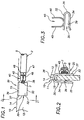
- FIGS. 1 and 2 illustrate a grounding clip system comprising generally a conductive panel 10 and a grounding clip 20 fastened thereto while providing preferably an electrical contact between a conductive wire 2 fastened to the clip and the conductive panel.
- the conductive panel 10 may be part of an appliance or some other article, for example in an electrical control application, and comprises opposing sides 11 and 12 and a panel edge 14 therebetween.
- the panel 10 has a recessed edge portion 15 having a length along the panel edge 14 greater than or at least as long as the length of the clip 20 to permit recessing all or portions of the clip 20 below the panel edge 14, as discussed further below. More generally, the panel 10 does not have a recessed edge portion, and in those applications or systems only an insubstantial portion of the clip 20 protrudes from the panel edge 14.
- the grounding clip 20 comprises a generally U-shape spring clamp 30 fastened to the panel 10, and a wire fastening member 40 extending therefrom to which the wire 2 is fastened, as discussed further below.
- the spring clamp 30 comprises generally first and second opposing walls 32 and 34 extending from opposing sides of a curved base portion 36, or bight, thereof.
- the first and second walls 32 and 34 each have a leading edge portion 33 and 35, respectively, forming an open end of the spring clamp opposite the bight 36 thereof.
- first and second walls 32 and 34 each comprise opposing inner and outer sides, the inner side of the first wall facing the inner side of the second wall.
- first and second walls each have opposing ends 37 and 38 between the curved base portion 36 and the leading edge portions 33 and 35 thereof, thus forming opposing ends of the spring clamp 30.
- the spring clamp 30 is fastened to the panel 10 with the curved base portion 36 of the spring clamp disposed over the panel edge 14 or 15, depending on the panel configuration, the first wall 32 adjacent one side of the panel, and the second wall 34 adjacent the other side of the panel.
- one or both of the leading edge portions of the spring clip are configured to diverge outwardly, thereby easing initial installation of the open end of the clip about the panel.
- one or both of the first and second side walls of the spring clamp may converge from the bight toward the other to facilitate clamping action when the spring clamp is disposed about the panel, for example the walls may have a skewed chevron shape, so that the spacing between portions of the walls is less that the thickness of the panel.
- Spring clamp walls having one or more outwardly diverging leading portions are particularly desirable in embodiments where the spacing between portions of the opposing walls is less than the thickness of the panel.
- the side walls of the spring clamp 30 are generally parallel to each other, and the leading edge 35 of the second wall 34 diverges outwardly from the other side wall 32 to facilitate installation of the clip on the panel.
- the second wall 34 also includes a barb 39 protruding from the inner side thereof as discussed below.
- a barb 39 protrudes from the inner side of one of the first and second walls of the spring clip for engagement with the panel, thereby improving electrical contact therewith.
- a barb 39 protrudes inwardly from only the second wall 34, preferably along an end thereof but alternately from any portion thereof. Locating the one or more barbs on only the second wall 34 allows the first wall 32 of the spring clip 30 without any barbs and the wire fastening member 40 thereof to be drawn and mounted directly against a side of the panel 10, thereby minimizing the mounting profile of the grounding clip and wire, particularly the protrusion of the wire fastening member 40 and wire 2 from the side of the panel and maximising the grounding contact between the panel side and wall 32.
- the wire fastening member extends generally from an end of one of the walls of the spring clamp between the curved base portion and the leading edge portion thereof.
- the wire fastening member 40 extends from the end 38 of the first wall 32 of the spring clamp 30 medially between the curved base portion 36 and the leading edge portion 33 of the spring clamp.
- the same or a second wire fastening member may extend alternately from the opposing end 37 of the spring clamp.
- the wire 2 is fastened preferably to a wire mounting surface on the outer side of the wire fastening member 40 opposite the panel 30, when the clip is fastened thereto, whereby a portion of the wire fastening member is immediately adjacent the panel to reduce the clip and wire mounting profile.
- the wire fastening member 40 and the wire 2 fastened thereto are both disposed directly adjacent the side of the panel 10 and are both spaced apart from the panel edge 14, whereby only the curved base portion 36 of the grounding clip protrudes insubstantially beyond the panel edge 14 or 15.
- the wire fastening member 40 comprises preferably a fastening flange 42 with a distal end portion 44 extending from the end 38 of the first wall 32.
- the fastening flange 42 is disposed medially between the curved base portion 36 of the spring clamp 30 and the leading edge portion 33 of the first wall.
- the fastening flange 42 includes opposing inner and outer sides corresponding to the opposing inner and outer sides of the first wall.
- the fastening flange 42 also comprises a mounting surface 43 on the outer sides thereof to which the wire is fastenable so that the wire is disposed on the side of the first wall 32 opposite the panel when the grounding clip is fastened thereto.
- the location of the wire fastening member 40 spaced away from the bight 36 of the spring clip 30 ensures that the wire 2 fastened thereto will not protrude above the panel edge, as is common with prior art grounding clips. Also, the extension of the wire fastening member 40 from the wall 32 of the spring clip along the side of the panel, and the mounting of the wire 2 on the clip opposite the panel minimizes the extent to which the wire protrudes from the clip and from the panel, thereby reducing the overall profile of the clip and wire assembly and reducing space utilization thereby.
- the wire 2 is preferably fastened to the wire fastening member 40 by barrel forming arms extending from the wire fastening member thereabout for crimping about the wire.
- arms 45 and 46 extend from the outer side of the fastening flange, also shown in FIG. 3 and partly in FIG. 4.
- the arms 45 and 46 are crimped about a conductive portion 3 of the wire 2.
- the exemplary wire fastening flange 40 also comprises secondary arms 47 and 48 nearer the distal end portion thereof, also shown partly in FIG. 4, for crimping about an electrically insulating outer sheath portion 5 of the wire.
- the wire fastening member 40 may comprise a more completely formed barrel portion which is crimped about a conductive wire portion disposed therein.
- the wire may be fastened to the wire fastening member by other known structure or means, including welding and soldering.
- the panel edge 14 has a recessed portion 15 having a length along the panel edge 14 sufficiently wide to accommodate the clip 20 when fastened to the panel 10.
- the depth of the recessed edge 15 from the panel edge 14 is preferably sufficiently deep, for example as deep as the bight 36 of the spring clamp 30, so that no portion of the clip protrudes above the panel edge 14, whereby a lid or cover, not shown, may be mounted on the panel edge without obstruction.
- the portion of the clip and particularly the bight thereof protrudes so insubstantially from the panel edge that a lid or cover nevertheless may be mounted on the edge 14 without substantial interference by the clip in the absence of the recessed edge portion 15.
- the grounding clip 20 is preferably a unitary metal member comprising for example spring steel, or stainless steel, or some other metal material.
- the grounding clip may be formed in a stamping operation.
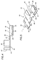
- FIG. 5 illustrates for example the grounding clip manufactured in strip form, wherein a strip of metal 60 is initially stamped to form a repeating series or sequence of first, second and third members 62, 63, and 64, respectively, which are subsequently formed into the spring clamp, and wire fastening member, respectively.
- Each sequence of the first, second and third members are spaced apart by a small carrier tab 66, which is easily broken to separate the completely formed grounding clips.
- Manufacturing the grounding clips of the present invention in strip form eliminates the necessity for costly and wasteful separate carrier members used commonly in the manufacture of prior art grounding clips.
Landscapes
- Clamps And Clips (AREA)
- Installation Of Indoor Wiring (AREA)
Abstract
Description
Claims (9)
- A grounding clip (20) comprising:a generally U-shape spring clamp (30) having first (32) and second (34) opposing walls extending from a curved base portion (36) thereof,the first and second walls (32,34) each having a leading edge portion (33,35) opposite the curved base portion (36), the first and second walls (32,34) each having opposing inner and outer sides, the inner side of the first wall facing the inner side of the second wall, the first and second walls (32,34) each having opposing ends between the curved base portion and the leading edge portions thereof; and,a wire fastening member (40) extending from an end (38) of the first wall (32) between the curved base portion (36) of the spring clamp (30) and the leading edge portion (33) thereof.
- A grounding clip according to claim 1, including a wire mounting portion on a side of the wire fastening member (40) corresponding to the outer side of the first wall (32).
- A grounding clip according to claim 1 or 2, including a barb (39) protruding from the inner side of one of the first and second walls (32,34).
- A grounding clip according to claim 1 or 2, including a barb (39) protruding from the inner side of the second wall (34) of the spring clamp (30) along an end (37,38) thereof.
- A grounding clip according to any one of the preceding claims, which is a unitary member.
- A grounding clip according to any one of the preceding claims, wherein the wire fastening member (40) has a fastening flange (44) with a distal end portion extending from the end (38) of the first wall (32), the fastening flange (44) disposed medially between the curved base portion (36) of the spring clamp (30) and the leading edge portion (33) of the first wall (32), the fastening flange (44) having opposing inner and outer sides corresponding to the opposing inner and outer sides of the first wall (32).
- A grounding clip according to claim 6, also including a wire mounting surface (45,46) on the outer side of the fastening flange (44).
- A grounding clip according to claim 6 or 7, also including barrel forming arms (47,48) extending from the fastening flange (44).
- A grounding clip system comprising:a conductive panel (10) having opposing sides (12) and a panel edge (14) therebetween;a grounding clip (20) in accordance with any one of the preceding claims,the spring clamp (30) fastened to the panel (10) with the curved base portion (36) disposed over the panel edge (14), the first wall (32) adjacent one side (12) of the panel (10) and the second wall (34) adjacent the other side of the panel (10; and,a wire (2) fastened to the wire fastening member (40) and spaced apart from the panel edge (14),
whereby, at most, only the curved base portion (36) of the grounding clip (20) protrudes beyond the panel edge (14).
Applications Claiming Priority (2)
| Application Number | Priority Date | Filing Date | Title |
|---|---|---|---|
| US368239 | 1999-08-04 | ||
| US09/368,239 US6276947B1 (en) | 1999-08-04 | 1999-08-04 | U-crimp |
Publications (3)
| Publication Number | Publication Date |
|---|---|
| EP1075045A2 true EP1075045A2 (en) | 2001-02-07 |
| EP1075045A3 EP1075045A3 (en) | 2002-02-13 |
| EP1075045B1 EP1075045B1 (en) | 2005-03-30 |
Family
ID=23450433
Family Applications (1)
| Application Number | Title | Priority Date | Filing Date |
|---|---|---|---|
| EP00306182A Expired - Lifetime EP1075045B1 (en) | 1999-08-04 | 2000-07-20 | Grounding clip and system |
Country Status (9)
| Country | Link |
|---|---|
| US (1) | US6276947B1 (en) |
| EP (1) | EP1075045B1 (en) |
| JP (1) | JP4414071B2 (en) |
| KR (1) | KR100753530B1 (en) |
| CN (1) | CN1147033C (en) |
| CA (1) | CA2314638C (en) |
| DE (1) | DE60019037T2 (en) |
| ES (1) | ES2238971T3 (en) |
| TW (1) | TW497302B (en) |
Cited By (1)
| Publication number | Priority date | Publication date | Assignee | Title |
|---|---|---|---|---|
| GB2465414A (en) * | 2008-11-19 | 2010-05-26 | Jonathan Lloyd Evans | Electrical connector with an earth wire |
Families Citing this family (29)
| Publication number | Priority date | Publication date | Assignee | Title |
|---|---|---|---|---|
| US20020098743A1 (en) * | 1998-04-17 | 2002-07-25 | Schell Mark S. | Power connector |
| US6546179B2 (en) * | 2001-01-25 | 2003-04-08 | Hector D. Petri | Guide for routing cables through panel openings |
| KR100425783B1 (en) * | 2001-06-15 | 2004-04-03 | 주식회사 뉴웰텔레콤 | Structure of the earth pin for protector |
| US6752368B2 (en) | 2002-10-30 | 2004-06-22 | Alcoa Inc. | Clamping device and method for grasping a workpiece |
| US6997722B2 (en) * | 2003-03-25 | 2006-02-14 | Elma Electronic Inc. | ESD system for grounding electronics within an enclosure |
| WO2007093544A1 (en) * | 2006-02-17 | 2007-08-23 | Brose Fahrzeugteile Gmbh & Co. Kg | Radio-suppressed drive unit, in particular for driving a motor vehicle fan |
| US20090241298A1 (en) * | 2008-04-01 | 2009-10-01 | Illinois Tool Works Inc. | Pre-cut seal for strap |
| US7686625B1 (en) | 2008-11-07 | 2010-03-30 | Tyco Electronics Corporation | Grounding clip |
| KR101045390B1 (en) * | 2009-01-05 | 2011-06-30 | 창원환경산업 주식회사 | Manure treatment device by electrolysis |
| JP4465406B1 (en) * | 2009-04-16 | 2010-05-19 | 株式会社屋根技術研究所 | Connecting member |
| JP4915707B2 (en) * | 2009-11-27 | 2012-04-11 | 関東自動車工業株式会社 | Clamp |
| US8955259B2 (en) | 2011-06-09 | 2015-02-17 | A. Raymond & Cie | Solar panel attachment system for a roof |
| US8894424B2 (en) | 2011-08-29 | 2014-11-25 | A. Raymond Et Cie | Universal clip apparatus for solar panel assembly |
| US8590223B2 (en) * | 2011-08-29 | 2013-11-26 | A. Raymond Et Cie | Solar panel assembly attachment apparatus |
| DE112013001440T5 (en) * | 2012-03-15 | 2015-01-22 | Autonetworks Technologies, Ltd. | Connection and wire provided with a connection |
| US20130240008A1 (en) * | 2012-03-16 | 2013-09-19 | Christopher Baker | System and method for mounting photovoltaic modules |
| US20140220834A1 (en) * | 2013-02-04 | 2014-08-07 | Dynoraxx, Inc. | Solar panel grounding system and clip |
| USD740113S1 (en) * | 2013-03-15 | 2015-10-06 | Hubbell Incorporated | Clip-on bonding washer |
| US9865939B2 (en) | 2016-02-08 | 2018-01-09 | Microsoft Technology Licensing, Llc | Connecting element with a spring tab |
| US10852038B2 (en) * | 2016-04-13 | 2020-12-01 | Elie Rothschild | Bonding jumper clip for solar panels |
| JP6720042B2 (en) * | 2016-09-30 | 2020-07-08 | 日本航空電子工業株式会社 | Cable connection structure and cable connector |
| CN106785537A (en) * | 2016-12-26 | 2017-05-31 | 池州信安信息技术有限公司 | Sim card socket |
| CN106711645A (en) * | 2016-12-26 | 2017-05-24 | 池州信安信息技术有限公司 | Sim card connector |
| CN106848668A (en) * | 2017-04-01 | 2017-06-13 | 河南鑫海电力设备有限公司 | A kind of electrical fitting |
| DE102019006783A1 (en) * | 2019-09-27 | 2021-04-01 | Drägerwerk AG & Co. KGaA | Clamping device and sensor cable |
| EP3832810B1 (en) * | 2019-12-02 | 2025-11-19 | Andreas Stihl AG & Co. KG | Motor-driven gardening and / or forestry machine comprising a plug connector for electrically connecting a terminal to an electrical line of a motor-driven garden and / or forestry machine |
| CN111342393A (en) * | 2020-04-02 | 2020-06-26 | 国网浙江武义县供电有限公司 | Hook-type insulating rod |
| CN111952916A (en) * | 2020-08-11 | 2020-11-17 | 广东电网有限责任公司 | Simple binding clip device for new low-voltage distribution lines |
| DE102021104559B4 (en) * | 2021-02-25 | 2022-12-22 | Hanwha Q Cells Gmbh | Contact for a photovoltaic module and a method for forming a contact |
Family Cites Families (19)
| Publication number | Priority date | Publication date | Assignee | Title |
|---|---|---|---|---|
| US3340494A (en) | 1965-09-13 | 1967-09-05 | Illinois Tool Works | Electrical connector device |
| US3686609A (en) | 1971-04-13 | 1972-08-22 | Essex International Inc | Ground terminal |
| US4126369A (en) | 1977-12-19 | 1978-11-21 | Illinois Tool Works | Electronic component terminal bridging assembly |
| US4553802A (en) | 1981-08-03 | 1985-11-19 | Illinois Tool Works Inc. | Modular bridging clip |
| US4439971A (en) * | 1982-03-24 | 1984-04-03 | Woodrite, Inc. | Panel connector |
| US4588240A (en) | 1983-11-16 | 1986-05-13 | Ruehl William E | Bridging clip |
| US4826078A (en) * | 1987-11-13 | 1989-05-02 | Imo Delaval Inc. | Wire-to-track-base retainer clip and keeper |
| US4874336A (en) * | 1988-03-15 | 1989-10-17 | Amp Incorporated | Shielded electrical connector for printed circuit board mounting |
| US4993959A (en) | 1990-01-19 | 1991-02-19 | Amp Incorporated | Grounding clip |
| JP2516103Y2 (en) * | 1990-05-28 | 1996-11-06 | 日立電線株式会社 | Communication cable connection structure |
| JPH0449468U (en) * | 1990-08-31 | 1992-04-27 | ||
| EP0504469B1 (en) * | 1991-03-22 | 1994-09-14 | Siemens Aktiengesellschaft | Electric contact connection |
| US5076626A (en) * | 1991-04-11 | 1991-12-31 | Tiddy Junius A | Method and device for repairing or protecting a door and kit for doing same |
| JP2553430Y2 (en) * | 1991-08-02 | 1997-11-05 | 日本端子株式会社 | Electrical connector |
| US5181867A (en) * | 1992-05-08 | 1993-01-26 | General Motors Corporation | Electrical sleeve terminal |
| FR2697060B1 (en) * | 1992-10-15 | 1994-11-18 | Rapid Sa | Nut in the form of a clamp especially for electrical connection. |
| US5451167A (en) | 1994-07-28 | 1995-09-19 | Illinois Tool Works Inc. | Grounding clip |
| US5660297A (en) * | 1994-10-24 | 1997-08-26 | Enlight Corporation | Non-screw assembled casing for computer mainframe |
| US6106310A (en) * | 1997-11-19 | 2000-08-22 | The Whitaker Corporation | Panel-grounding contact |
-
1999
- 1999-08-04 US US09/368,239 patent/US6276947B1/en not_active Expired - Lifetime
-
2000
- 2000-07-13 KR KR1020000040232A patent/KR100753530B1/en not_active Expired - Fee Related
- 2000-07-20 EP EP00306182A patent/EP1075045B1/en not_active Expired - Lifetime
- 2000-07-20 DE DE60019037T patent/DE60019037T2/en not_active Expired - Fee Related
- 2000-07-20 ES ES00306182T patent/ES2238971T3/en not_active Expired - Lifetime
- 2000-07-27 CA CA002314638A patent/CA2314638C/en not_active Expired - Fee Related
- 2000-07-27 JP JP2000226500A patent/JP4414071B2/en not_active Expired - Fee Related
- 2000-08-01 TW TW089115461A patent/TW497302B/en not_active IP Right Cessation
- 2000-08-04 CN CNB001212095A patent/CN1147033C/en not_active Expired - Fee Related
Cited By (1)
| Publication number | Priority date | Publication date | Assignee | Title |
|---|---|---|---|---|
| GB2465414A (en) * | 2008-11-19 | 2010-05-26 | Jonathan Lloyd Evans | Electrical connector with an earth wire |
Also Published As
| Publication number | Publication date |
|---|---|
| KR100753530B1 (en) | 2007-08-30 |
| CA2314638C (en) | 2004-06-01 |
| DE60019037D1 (en) | 2005-05-04 |
| DE60019037T2 (en) | 2005-08-11 |
| JP4414071B2 (en) | 2010-02-10 |
| KR20010021077A (en) | 2001-03-15 |
| EP1075045A3 (en) | 2002-02-13 |
| CN1283882A (en) | 2001-02-14 |
| EP1075045B1 (en) | 2005-03-30 |
| ES2238971T3 (en) | 2005-09-16 |
| TW497302B (en) | 2002-08-01 |
| JP2001102107A (en) | 2001-04-13 |
| CN1147033C (en) | 2004-04-21 |
| US6276947B1 (en) | 2001-08-21 |
| CA2314638A1 (en) | 2001-02-04 |
Similar Documents
| Publication | Publication Date | Title |
|---|---|---|
| EP1075045B1 (en) | Grounding clip and system | |
| US6106310A (en) | Panel-grounding contact | |
| US7686625B1 (en) | Grounding clip | |
| US8708733B2 (en) | Large deflection constrained insulation displacement terminal and connector | |
| US5941741A (en) | One-piece contact spring | |
| JP3532428B2 (en) | Terminal | |
| US4993959A (en) | Grounding clip | |
| CN105164857B (en) | voltage contact device | |
| US20080132103A1 (en) | Female terminal | |
| EP0112144B1 (en) | Electrical connector for flat flexible cable | |
| US4895526A (en) | Connecting terminal block for electrical apparatus | |
| GB2183937A (en) | Female electrical contact member | |
| US5133672A (en) | Insulation displacement terminal | |
| US6231393B1 (en) | Electrical connector | |
| US20160315402A1 (en) | Terminal block | |
| US20030100205A1 (en) | Device for the electrically conductive contacting of an electrically conductive part of an elongated body, in particular a tube or cable | |
| JP3278017B2 (en) | Receptacle contact | |
| GB2206459A (en) | Crimp contact terminal for high voltage resisitor wire | |
| HK1035442A (en) | Grounding clip and system | |
| JPH0534664U (en) | Wire crimp terminal | |
| EP1258961A2 (en) | Apparatus for shielding conductors from electromagnetic and other interference | |
| US6341978B1 (en) | Press-connecting terminal | |
| US4040712A (en) | Double-acting electrical receptacle | |
| JP2002216908A (en) | Electromagnetic wave shielding structure | |
| MXPA00007600A (en) | Grounding clip and system |
Legal Events
| Date | Code | Title | Description |
|---|---|---|---|
| PUAI | Public reference made under article 153(3) epc to a published international application that has entered the european phase |
Free format text: ORIGINAL CODE: 0009012 |
|
| AK | Designated contracting states |
Kind code of ref document: A2 Designated state(s): AT BE CH CY DE DK ES FI FR GB GR IE IT LI LU MC NL PT SE Kind code of ref document: A2 Designated state(s): DE ES FR GB IT |
|
| AX | Request for extension of the european patent |
Free format text: AL;LT;LV;MK;RO;SI |
|
| PUAL | Search report despatched |
Free format text: ORIGINAL CODE: 0009013 |
|
| AK | Designated contracting states |
Kind code of ref document: A3 Designated state(s): AT BE CH CY DE DK ES FI FR GB GR IE IT LI LU MC NL PT SE |
|
| AX | Request for extension of the european patent |
Free format text: AL;LT;LV;MK;RO;SI |
|
| 17P | Request for examination filed |
Effective date: 20020716 |
|
| AKX | Designation fees paid |
Free format text: DE ES FR GB IT |
|
| 17Q | First examination report despatched |
Effective date: 20040607 |
|
| GRAP | Despatch of communication of intention to grant a patent |
Free format text: ORIGINAL CODE: EPIDOSNIGR1 |
|
| GRAS | Grant fee paid |
Free format text: ORIGINAL CODE: EPIDOSNIGR3 |
|
| GRAA | (expected) grant |
Free format text: ORIGINAL CODE: 0009210 |
|
| AK | Designated contracting states |
Kind code of ref document: B1 Designated state(s): DE ES FR GB IT |
|
| REG | Reference to a national code |
Ref country code: GB Ref legal event code: FG4D |
|
| REF | Corresponds to: |
Ref document number: 60019037 Country of ref document: DE Date of ref document: 20050504 Kind code of ref document: P |
|
| REG | Reference to a national code |
Ref country code: IE Ref legal event code: FG4D |
|
| PGFP | Annual fee paid to national office [announced via postgrant information from national office to epo] |
Ref country code: DE Payment date: 20050831 Year of fee payment: 6 |
|
| REG | Reference to a national code |
Ref country code: ES Ref legal event code: FG2A Ref document number: 2238971 Country of ref document: ES Kind code of ref document: T3 |
|
| PLBE | No opposition filed within time limit |
Free format text: ORIGINAL CODE: 0009261 |
|
| STAA | Information on the status of an ep patent application or granted ep patent |
Free format text: STATUS: NO OPPOSITION FILED WITHIN TIME LIMIT |
|
| ET | Fr: translation filed | ||
| 26N | No opposition filed |
Effective date: 20060102 |
|
| PG25 | Lapsed in a contracting state [announced via postgrant information from national office to epo] |
Ref country code: DE Free format text: LAPSE BECAUSE OF NON-PAYMENT OF DUE FEES Effective date: 20070201 |
|
| REG | Reference to a national code |
Ref country code: HK Ref legal event code: WD Ref document number: 1035442 Country of ref document: HK |
|
| PGFP | Annual fee paid to national office [announced via postgrant information from national office to epo] |
Ref country code: ES Payment date: 20090727 Year of fee payment: 10 Ref country code: FR Payment date: 20090717 Year of fee payment: 10 |
|
| PGFP | Annual fee paid to national office [announced via postgrant information from national office to epo] |
Ref country code: GB Payment date: 20090727 Year of fee payment: 10 |
|
| PGFP | Annual fee paid to national office [announced via postgrant information from national office to epo] |
Ref country code: IT Payment date: 20090728 Year of fee payment: 10 |
|
| GBPC | Gb: european patent ceased through non-payment of renewal fee |
Effective date: 20100720 |
|
| REG | Reference to a national code |
Ref country code: FR Ref legal event code: ST Effective date: 20110331 |
|
| PG25 | Lapsed in a contracting state [announced via postgrant information from national office to epo] |
Ref country code: IT Free format text: LAPSE BECAUSE OF NON-PAYMENT OF DUE FEES Effective date: 20100720 Ref country code: FR Free format text: LAPSE BECAUSE OF NON-PAYMENT OF DUE FEES Effective date: 20100802 |
|
| PG25 | Lapsed in a contracting state [announced via postgrant information from national office to epo] |
Ref country code: GB Free format text: LAPSE BECAUSE OF NON-PAYMENT OF DUE FEES Effective date: 20100720 |
|
| REG | Reference to a national code |
Ref country code: ES Ref legal event code: FD2A Effective date: 20110818 |
|
| PG25 | Lapsed in a contracting state [announced via postgrant information from national office to epo] |
Ref country code: ES Free format text: LAPSE BECAUSE OF NON-PAYMENT OF DUE FEES Effective date: 20100721 |