EP1074981A2 - Optical pickup - Google Patents
Optical pickup Download PDFInfo
- Publication number
- EP1074981A2 EP1074981A2 EP00306703A EP00306703A EP1074981A2 EP 1074981 A2 EP1074981 A2 EP 1074981A2 EP 00306703 A EP00306703 A EP 00306703A EP 00306703 A EP00306703 A EP 00306703A EP 1074981 A2 EP1074981 A2 EP 1074981A2
- Authority
- EP
- European Patent Office
- Prior art keywords
- optical pickup
- conductive
- land
- lens holder
- damper base
- Prior art date
- Legal status (The legal status is an assumption and is not a legal conclusion. Google has not performed a legal analysis and makes no representation as to the accuracy of the status listed.)
- Withdrawn
Links
Images


Classifications
-
- G—PHYSICS
- G11—INFORMATION STORAGE
- G11B—INFORMATION STORAGE BASED ON RELATIVE MOVEMENT BETWEEN RECORD CARRIER AND TRANSDUCER
- G11B7/00—Recording or reproducing by optical means, e.g. recording using a thermal beam of optical radiation by modifying optical properties or the physical structure, reproducing using an optical beam at lower power by sensing optical properties; Record carriers therefor
- G11B7/08—Disposition or mounting of heads or light sources relatively to record carriers
- G11B7/09—Disposition or mounting of heads or light sources relatively to record carriers with provision for moving the light beam or focus plane for the purpose of maintaining alignment of the light beam relative to the record carrier during transducing operation, e.g. to compensate for surface irregularities of the latter or for track following
- G11B7/0925—Electromechanical actuators for lens positioning
- G11B7/0933—Details of stationary parts
-
- G—PHYSICS
- G11—INFORMATION STORAGE
- G11B—INFORMATION STORAGE BASED ON RELATIVE MOVEMENT BETWEEN RECORD CARRIER AND TRANSDUCER
- G11B7/00—Recording or reproducing by optical means, e.g. recording using a thermal beam of optical radiation by modifying optical properties or the physical structure, reproducing using an optical beam at lower power by sensing optical properties; Record carriers therefor
- G11B7/08—Disposition or mounting of heads or light sources relatively to record carriers
- G11B7/09—Disposition or mounting of heads or light sources relatively to record carriers with provision for moving the light beam or focus plane for the purpose of maintaining alignment of the light beam relative to the record carrier during transducing operation, e.g. to compensate for surface irregularities of the latter or for track following
- G11B7/0925—Electromechanical actuators for lens positioning
- G11B7/0932—Details of sprung supports
-
- G—PHYSICS
- G11—INFORMATION STORAGE
- G11B—INFORMATION STORAGE BASED ON RELATIVE MOVEMENT BETWEEN RECORD CARRIER AND TRANSDUCER
- G11B7/00—Recording or reproducing by optical means, e.g. recording using a thermal beam of optical radiation by modifying optical properties or the physical structure, reproducing using an optical beam at lower power by sensing optical properties; Record carriers therefor
- G11B7/08—Disposition or mounting of heads or light sources relatively to record carriers
- G11B7/09—Disposition or mounting of heads or light sources relatively to record carriers with provision for moving the light beam or focus plane for the purpose of maintaining alignment of the light beam relative to the record carrier during transducing operation, e.g. to compensate for surface irregularities of the latter or for track following
- G11B7/0925—Electromechanical actuators for lens positioning
- G11B7/0935—Details of the moving parts
-
- G—PHYSICS
- G11—INFORMATION STORAGE
- G11B—INFORMATION STORAGE BASED ON RELATIVE MOVEMENT BETWEEN RECORD CARRIER AND TRANSDUCER
- G11B7/00—Recording or reproducing by optical means, e.g. recording using a thermal beam of optical radiation by modifying optical properties or the physical structure, reproducing using an optical beam at lower power by sensing optical properties; Record carriers therefor
- G11B7/12—Heads, e.g. forming of the optical beam spot or modulation of the optical beam
- G11B7/22—Apparatus or processes for the manufacture of optical heads, e.g. assembly
Definitions
- This invention relates to an optical pickup suitable for use in an optical disk drive and, in particular, to an optical pickup in which an objective lens is elastically supported by a suspension member.
- the first conventional optical pickup comprises a lens holder 11, an objective lens 12 held by the lens holder 11, a damper base 13, and four conductive wires 14 as a suspension member for elastically suspending the lens holder 11 to the damper base 13.
- a cover 15 is connected to the damper base 13 and extends to cover the lens holder 11.
- the lens holder 11 is provided with a coil unit (not shown) electrically connected to the conductive wires 14.
- the cover 15 is provided with a magnet (not shown) placed adjacent to the coil unit.
- the cover 15 is held by a frame of a optical disk drive.
- Each of the conductive wires 14 penetrates the damper base 13 to have an end portion 14a exposed from the damper base 13.
- a flexible printed circuit (FPC) 16 is attached to the damper base 13.
- the FPC 16 has a plurality of electric circuits connected to the conductive wires 14 in the manner which will later be described.
- the coil unit is supplied with an electric signal from a control part of the optical disk drive through the FPC 16 and the conductive wires 14.
- the end portion 14a of each of the conductive wires 14 are provisionally fixed to the damper base 13 by the use of an adhesive as illustrated in Figs. 1A and 1 B.
- the end portion 14a is soldered to the FPC 16 as illustrated in Figs. 1C and 1D.
- the first conventional optical pickup is disadvantageous in the following respects.
- energizing is carried out to measure various characteristics by the use of a measuring instrument before the first conventional optical pickup is assembled into the housing.
- a probe of the measuring instrument is brought into direct contact with the end portion 14a of each of the conductive wires 14, i.e., the terminals, which are only provisionally fixed by the adhesive. Therefore, the conductive wires 14 are inevitably applied with additional force exerted by the probe. This makes it difficult to accurately measure kinetic characteristics.
- the adhesive since the conductive wires 14 are thereafter fixed to the FPC 16 by soldering, the adhesive may be melted by heat. In this event, the objective lens 12 is moved out of position.
- an intermediate substrate 17 is attached to the damper base 13.
- the end portion 14a of each of the conductive wires 14 are soldered to the intermediate substrate 17, as illustrated in Figs. 2A and 2B.
- various characteristics are measured by the use of the measuring instrument.
- the FPC 16 is soldered to a plurality of connection lands 18 formed on the intermediate substrate 17, as illustrated in Figs. 2C and 2D.
- the intermediate substrate 17 is provided with test pins (not shown) which are brought into contact with the probe.
- the conductive wires 4 may not directly be contacted by the probe and are therefore prevented from being applied with the additional force described in conjunction with the first conventional optical pickup.
- the number of parts is increased by provision of the intermediate substrate 17.
- the manhour required in the production process is also increased.
- an optical pickup including a lens holder, an objective lens held by the lens holder, a damper base, and a suspension member for elastically suspending the lens holder to the damper base.
- the damper base comprises a base body having a principal insulation surface, a first conductive land attached directly to the principal insulation surface and electrically connected to the suspension member, and a second conductive land attached directly to the principal insulation surface and electrically connected to the first conductive land for being electrically connected with a flexible circuit member.
- an optical pickup 1 is for use in an optical disk drive such as a CD-R (Compact Disk - Recordable) known in the art.
- CD-R Compact Disk - Recordable
- the optical pickup 1 comprises a lens holder 21, an objective lens 22 held at an end of the lens holder 21, a damper base 23, and four suspension wires or conductive wires 24 as a suspension member for elastically suspending the lens holder 21 to the damper base 23.
- Each of the conductive wires 24 is made of elastic wire member.
- a cover 25 is connected to the damper base 23 and extends to cover a part of the lens holder 21.
- a frame of the optical disk drive holds the cover 25.
- the lens holder 21 is provided with a coil unit 31 which will later be described.
- the cover 25 is provided with a magnet assembly 32 which is placed adjacent to the coil unit 31.
- the magnet assembly 32 comprises a yoke 33 supported by the cover 25 and first and second permanent magnets 34a and 34b coupled to first and second portions 33a and 33b of the yoke 33, respectively.
- the first and the second portions 33a and 33b of the yoke 33 are opposite to each other.
- the first and the second permanent magnets 34a and 34b are placed between the first and the second portions 33a and 33b to have a space therebetween and are fixedly attached to the first and the second portions 33a and 33b, respectively.
- the coil unit 31 comprises a focusing coil 31a and a tracking coil 31b electrically connected to the conductive wires 24 in the manner known in the art.
- the focusing coil 31 a is adapted to receive, in its center portion, the first yoke 33a and the first permanent magnet 34a.
- the tracking coil 31 b is placed in the space between the first and the second permanent magnet 34a and 34b to face the second permanent magnet 34b. It is to be noted that a gap is left between the magnet assembly 32 and each of the focusing and the tracking coils 31a and 31b.
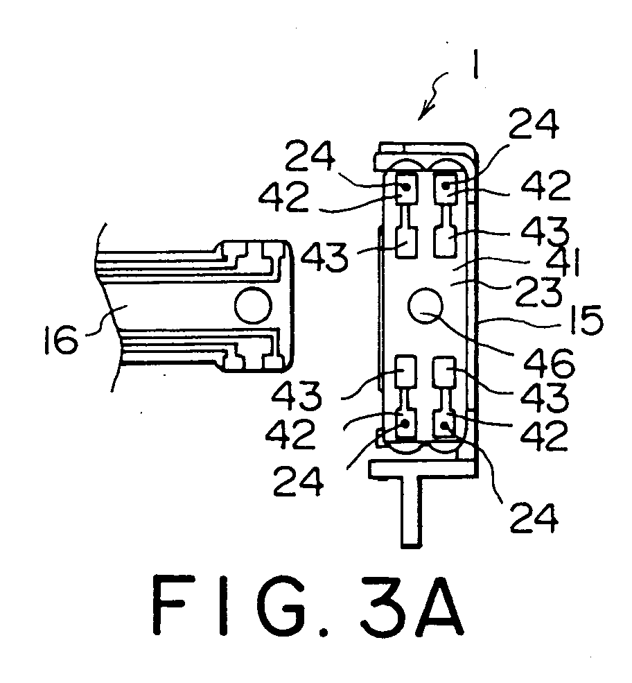
- the damper base 23 comprises a base body 41 made of transparent synthetic resin, four wire-fixing lands 42 as a first conductive land, and four FPC-connecting lands 43 as a second conductive land.
- the base body 41 comprises a fixed portion 44 and a pair of wire insertion portions 45 at opposite ends of the fixed portion 44.
- the fixed portion 44 is of a generally plate-like shape and has first and second surfaces 44a and 44b opposed to each other.
- the wire insertion portions 45 protrude from the second surface 44b of the fixed portion 44.
- the first surface 44a is referred to as a principal insulation surface.
- the fixed portion 44 is provided with a through hole 46 at its center and fixed to the cover 25 by screws (not shown) inserted into the through hole 46.
- the fixed portion 44 is provided with four through holes 47, two of which being at an end portion thereof and other two of which being at another end portion thereof.
- Each of the wire insertion portions 45 has a cylindrical shape with a gourd-like section. At each of end portions of the fixed portion 44, two of the through holes 47 are communicated with each of the wire insertion portions 45.
- the wire insertion portions 45 are filled with damping members or materials 48 to attenuate vibration of the conductive wires 24 passing through the wire insertion portions 45, respectively.
- Each of the damping members is made of gel material known in the art.
- Each of the wire-fixing lands 42 is formed directly on or attached directly to the first surface 44a of the fixed portion 44 to surround each corresponding through hole 46.
- the end portions of the conductive wires 24 protrude from the first surface 44a of the fixed portion 44 through the wire insertion portions 45 and the through holes 47 and soldered to the wire-fixing lands 42, respectively.
- the end portions of the conductive wires 24 are mechanically fixed to the damper base 23 and electrically connected to the wire-fixing lands 42.
- the other end portions of the conductive wires 24 are fixed to the lens holder 21.
- the damper base 23 elastically and swingably supports the lens holder 21 through the conductive wires 24.
- the FPC-connecting lands 43 are formed directly on or attached directly to the first surface 44a of the fixed portion 44 to be positioned inside the wire-fixing lands 42, respectively. A part of each FPC-connecting land 43 extends to reach the wire-fixing land 42 and is electrically connected thereto.
- the FPC 16 is attached to the first surface 44a of the fixed portion 44 and is connected to the FPC-connecting lands 43. Thus, the FPC 16 is electrically connected to the conductive wires 4 through the FPC-connecting lands 43 and the wire-fixing lands 42.
- a combination of the damper base 23, the wire-fixing lands 32, and the FPC-connecting lands 33 is produced by the use of a molded interconnect device (MID) production technique known in the art.
- MID molded interconnect device
- a molded interconnect device produced by the MID production technique is a three-dimensional circuit component comprising a plastic molded product and a conductive circuit formed thereon as a plating film.
- a mechanical function and an electrical function as desired.
- an optical function may be provided by the use of light reflectance of the plating film.
- various methods are available. In order to form the circuit on the plastic molded product by plating, use may be made of a photo-imaging method or a direct exposure method in dependence upon the configuration of the molded product or a circuit pattern of the circuit.
- the molded product is coated with a photomask and then subjected to ultraviolet exposure.
- a laser beam is used.
- Each of these methods is basically similar to a method of producing a printed circuit board, which utilizes a semi-additive technique or a subtractive technique and which is presently carried out for a glass epoxy substrate, but is characterized in that the circuit is formed on a three-dimensional injection molded product.
- These methods are called "one-shot methods". Use may be made of other methods, such as a film transfer method and a two-shot method.
- the film transfer method the circuit is formed on a film and transferred to the molded product.
- the two-shot method a circuit portion and a non-circuit portion are molded in two-color molding and the circuit is formed by plating.
- the end portions of the conductive wires 24 are inserted through the wire insertion portions 45 and the through holes 47.
- the end portions are soldered to the wire-fixing lands 42.
- the other ends of the conductive wires 24 are soldered to the lens holder 21 provided with the objective lens 22, the focusing coil 31 a, and the tracking coil 31 b.
- an assembly including the damper base 23 and the lens holder 21 is formed.
- the first yoke 33a and the first permanent magnet 34a attached thereto are placed within the center portion of the focusing coil 31 a and the second permanent magnet 34b attached to the second yoke 33b is faced to the tracking coil 31 b.
- the optical pickup 1 When the optical pickup 1 is completed, various characteristics of the optical pickup 1 are measured before the FPC 16 is connected thereto.
- the measurement of the various characteristics is carried out by bringing a probe of a measuring instrument (not shown) into press contact with the FPC-connecting lands 43.
- the probe of the measuring instrument is electrically conducted to each of the conductive wires 24 through each of the FPC-connecting lands 43, but is not directly contacted with the conductive wires 24 provisionally fixed by the adhesive. Therefore, the conductive wires 24 are prevented from movement so that the various characteristics of the optical pickup 1 for an optical disk can be accurately measured.
- the FPC-connecting lands 43 serve as test pins.
- the conductive wires 24 are soldered to the wire-fixing lands 42 at a first stage without provisionally fixing the conductive wires 24 by the adhesive. Therefore, the suspension wires 24 are prevented from movement thereof. This makes it possible to prevent the objective lens 22 from being moved out of position.
- the FPC 16 is soldered to the FPC-connecting lands 43. Since it is unnecessary to use the above-mentioned intermediate substrate, the FPC 16 can be simply connected to the conductive wires 24 through the FPC-connecting lands 43 without increasing the number of components.
- the damper base may be produced in various other manners, for example, by typical injection molding.
- the wire-fixing lands and the FPC-connecting lands obtained by punching a metal thin plate are adhered to the damper base body.
- the damper base has a base body 41 and is provided with a first and a second conductive land 42, 43 attached directly to a principal insulation surface of the base body.
- the first conductive land is electrically connected to the conductive wire.
- the second conductive land is electrically connected to the first conductive land and is for electrical connection to a flexible circuit member such as an FPC 16.
Landscapes
- Optical Recording Or Reproduction (AREA)
- Optical Head (AREA)
Abstract
Description
Claims (9)
- An optical pickup including a lens holder, an objective lens held by said lens holder, a damper base, and a suspension member for elastically suspending said lens holder from said damper base, said damper base comprising:a base body having a principal insulation surface;a first conductive land attached to said principal insulation surface and electrically connected to said suspension member; anda second conductive land for electrical connection to a flexible circuit member, said second conductive land being attached to said principal insulation surface and electrically connected to said first conductive land.
- An optical pickup as claimed in claim 1, further comprising:a coil unit held by said lens holder and electrically connected to said first conductive land through said suspension member; anda magnet assembly connected relative to said damper base and placed adjacent to said coil unit.
- An optical pickup as claimed in claim 2, further comprising a cover connected to said base body and extending to cover a part of said lens holder, said magnet assembly being supported by said cover.
- An optical pickup as claimed in claim 3, wherein said magnet assembly comprises:a yoke supported by said cover; anda permanent magnet coupled to said yoke.
- An optical pickup as claimed in claim 1, wherein said suspension member comprises a plurality of conductive elastic wires each of which elastically suspends said lens holder to said damper base.
- An optical pickup as claimed in claim 5, wherein said base body has a plurality of through holes each extending from said principal insulation surface, said conductive elastic wires extending through said through holes, respectively, said damper base further comprising a plurality of damping members placed in said through holes to attenuate vibration of said conductive elastic wires, respectively.
- An optical pickup as claimed in claim 6, wherein said first conductive land has a plurality of land portions, each of said conductive elastic wires has an end portion which protrudes from said principal insulation surface and connected to each of said land portions of the first conductive land.
- An optical pickup as claimed in claim 7, wherein said second conductive land has a plurality of land portions electrically connected to said land portions of first conductive land, respectively.
- An optical pickup as claimed in claim 1, wherein said base body is made of made of synthetic resin, a combination of said base body and said first and said second conductive lands being produced by an MID production technique.
Applications Claiming Priority (2)
| Application Number | Priority Date | Filing Date | Title |
|---|---|---|---|
| JP22234099 | 1999-08-05 | ||
| JP11222340A JP2001052360A (en) | 1999-08-05 | 1999-08-05 | Optical disk pickup |
Publications (3)
| Publication Number | Publication Date |
|---|---|
| EP1074981A2 true EP1074981A2 (en) | 2001-02-07 |
| EP1074981A8 EP1074981A8 (en) | 2001-05-16 |
| EP1074981A3 EP1074981A3 (en) | 2002-06-12 |
Family
ID=16780820
Family Applications (1)
| Application Number | Title | Priority Date | Filing Date |
|---|---|---|---|
| EP20000306703 Withdrawn EP1074981A3 (en) | 1999-08-05 | 2000-08-07 | Optical pickup |
Country Status (3)
| Country | Link |
|---|---|
| US (1) | US6246531B1 (en) |
| EP (1) | EP1074981A3 (en) |
| JP (1) | JP2001052360A (en) |
Families Citing this family (6)
| Publication number | Priority date | Publication date | Assignee | Title |
|---|---|---|---|---|
| EP1489606A1 (en) * | 1999-09-21 | 2004-12-22 | Matsushita Electric Industrial Co., Ltd. | An optical pickup with improved optical properties, and a method for manufacturing the optical pickup |
| KR100438776B1 (en) * | 2001-11-06 | 2004-07-05 | 삼성전자주식회사 | Hard disk drive comprising flexible printed circuit with damping material |
| US20060176582A1 (en) * | 2005-02-09 | 2006-08-10 | Thunk It, Llc | Refrigerator magnet with a magnifying apparatus |
| JP4187759B2 (en) * | 2006-08-08 | 2008-11-26 | Tdk株式会社 | Objective lens driving device, optical pickup using the same, and optical recording / reproducing device |
| JP5111157B2 (en) | 2008-02-27 | 2012-12-26 | キヤノン株式会社 | Photoelectric conversion device and imaging system using photoelectric conversion device |
| KR101309703B1 (en) * | 2012-01-31 | 2013-09-17 | 도시바삼성스토리지테크놀러지코리아 주식회사 | Objective Lens Driving Unit, and Optical Pickup Device and Disc Drive adopting the Unit |
Family Cites Families (7)
| Publication number | Priority date | Publication date | Assignee | Title |
|---|---|---|---|---|
| JPH03104027A (en) * | 1989-09-18 | 1991-05-01 | Sony Corp | Objective lens driver |
| JPH0696458A (en) * | 1992-07-28 | 1994-04-08 | Asahi Optical Co Ltd | Electromagnetic drive device for objective lens of optical information recording / reproducing device |
| US6069867A (en) * | 1994-06-09 | 2000-05-30 | Olympus Optical Company, Ltd. | Apparatus for supporting optical system of optical information recording/reproducing apparatus and method of manufacturing the same |
| JPH087305A (en) * | 1994-06-14 | 1996-01-12 | Olympus Optical Co Ltd | Apparatus for supporting optical system |
| JP3834831B2 (en) * | 1995-03-20 | 2006-10-18 | ソニー株式会社 | Objective lens driving device and optical pickup device using the objective lens driving device |
| JPH0916993A (en) * | 1995-06-30 | 1997-01-17 | Mitsumi Electric Co Ltd | Optical pickup device |
| JPH10312558A (en) * | 1997-05-14 | 1998-11-24 | Mitsumi Electric Co Ltd | Optical pickup device |
-
1999
- 1999-08-05 JP JP11222340A patent/JP2001052360A/en not_active Withdrawn
-
2000
- 2000-08-04 US US09/632,224 patent/US6246531B1/en not_active Expired - Fee Related
- 2000-08-07 EP EP20000306703 patent/EP1074981A3/en not_active Withdrawn
Also Published As
| Publication number | Publication date |
|---|---|
| EP1074981A8 (en) | 2001-05-16 |
| US6246531B1 (en) | 2001-06-12 |
| JP2001052360A (en) | 2001-02-23 |
| EP1074981A3 (en) | 2002-06-12 |
Similar Documents
| Publication | Publication Date | Title |
|---|---|---|
| US5056891A (en) | Method of preparing information reading apparatus and objective lens suspension body | |
| JP3411603B2 (en) | Objective lens electromagnetic drive for optical information recording / reproducing device | |
| EP1128364B1 (en) | Lens driving apparatus for a disk player | |
| JP2001229555A (en) | Lens driving device, suspension unit for lens driving device and method for manufacturing lens driving device | |
| US6246531B1 (en) | Optical pickup for enabling accurate measurement of various characteristics thereof without increasing the number or parts | |
| KR100888938B1 (en) | Objective lens driving apparatus, optical pickup apparatus and optical information recording and / or reproducing apparatus | |
| JPH0696458A (en) | Electromagnetic drive device for objective lens of optical information recording / reproducing device | |
| JPH11211956A (en) | Optical element or holder for the same | |
| JPH09190644A (en) | Lens driving device and its manufacture | |
| JPH11211969A (en) | Support device for optical system movable part | |
| JP3306197B2 (en) | Objective lens drive | |
| KR19980086189A (en) | Optical Pickup Actuator | |
| KR100735856B1 (en) | Optical pickup | |
| CN222913946U (en) | Optical drive assembly | |
| JPH0452815Y2 (en) | ||
| JP2900825B2 (en) | Optical pickup device and method of manufacturing the same | |
| KR100403145B1 (en) | Making method of one body type optical pick-up actuator | |
| KR100220522B1 (en) | Optical Pickup Actuator | |
| KR0175810B1 (en) | A testing ball of the pick up base | |
| KR0124821Y1 (en) | A supporter of optical pick-up actuator | |
| KR20010064031A (en) | Optical pickup assembly | |
| JPH05342606A (en) | Objective lens drive | |
| JP2000298856A (en) | Optical head and method of manufacturing the same | |
| JP3813447B2 (en) | Optical pickup device | |
| JPH1064111A (en) | Objective lens drive |
Legal Events
| Date | Code | Title | Description |
|---|---|---|---|
| PUAI | Public reference made under article 153(3) epc to a published international application that has entered the european phase |
Free format text: ORIGINAL CODE: 0009012 |
|
| AK | Designated contracting states |
Kind code of ref document: A2 Designated state(s): AT BE CH CY DE DK ES FI FR GB GR IE IT LI LU MC NL PT SE |
|
| AX | Request for extension of the european patent |
Free format text: AL;LT;LV;MK;RO;SI |
|
| RAP1 | Party data changed (applicant data changed or rights of an application transferred) |
Owner name: MITSUMI ELECTRIC COMPANY LTD. |
|
| RAP1 | Party data changed (applicant data changed or rights of an application transferred) |
Owner name: FCI JAPAN K.K. Owner name: MITSUMI ELECTRIC COMPANY LTD. |
|
| PUAL | Search report despatched |
Free format text: ORIGINAL CODE: 0009013 |
|
| AX | Request for extension of the european patent |
Free format text: AL;LT;LV;MK;RO;SI |
|
| AKX | Designation fees paid | ||
| REG | Reference to a national code |
Ref country code: DE Ref legal event code: 8566 |
|
| STAA | Information on the status of an ep patent application or granted ep patent |
Free format text: STATUS: THE APPLICATION IS DEEMED TO BE WITHDRAWN |
|
| 18D | Application deemed to be withdrawn |
Effective date: 20030301 |